Table of Contents
Advertisement
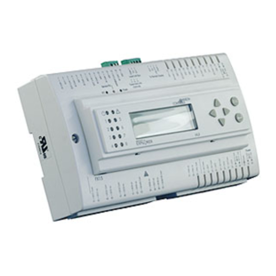
Introduction to FX15............................................................................... 3
Key Concepts ....................................................................................................... 4
FX15 ...................................................................................................................................4
Installation............................................................................................... 5
North American Emissions Compliance..............................................................................6
Detailed Procedures ...........................................................................................7
Mounting Instructions........................................................................................................ 7
Assembling the Integrated MUI......................................................................................... 8
Connection Details.......................................................................................................... 10
Connection Details for the N2 Open Card ...................................................................... 14
Connection Details for the LON Card ............................................................................. 17
Connection Details for the Remote User Interface ......................................................... 19
Connection Details for the Programming Key................................................................. 22
Inputs and Outputs............................................................................... 26
Inputs and Outputs............................................................................... 26
Introduction .......................................................................................................26
Key Concepts ....................................................................................................27
Detailed Procedures .........................................................................................28
Isolation Diagram ............................................................................................................ 28
FX15 I/Os Powered at 24 VAC .........................................................................................29
Analog Inputs .................................................................................................................. 30
Digital Inputs ................................................................................................................... 36
Analog Outputs ............................................................................................................... 37
Digital Outputs ................................................................................................................ 39
Extension Modules ......................................................................................................... 42
Troubleshooting................................................................................................44
Reading 9999 or Invalid from the Analog Inputs............................................................. 44
© 2005 Johnson Controls, Inc.
Code Number LIT-12011107
FX15 Controller
Technical Bulletin FX15 Controller
Issue Date November 14, 2005
www.johnsoncontrols.com
1
Advertisement
Table of Contents

Summary of Contents for Explorer FX15
-
Page 1: Table Of Contents
Inputs and Outputs................26 Introduction .......................26 Key Concepts ....................27 Detailed Procedures ..................28 Isolation Diagram ......................28 FX15 I/Os Powered at 24 VAC ..................29 Analog Inputs ........................30 Digital Inputs ........................36 Analog Outputs ....................... 37 Digital Outputs ........................ 39 Extension Modules ......................42 Troubleshooting....................44... - Page 2 User Interface ......................... 48 Security ........................... 50 Specifications and Technical Data............51 Ordering Codes ....................51 Technical Specifications ..................54 I/O Technical Details....................... 54 N2 Open Card......................... 56 LON Connection ......................56 Programming Key ......................57 FX15 ..........................57 FX15 Extended Range ....................58...
-
Page 3: Introduction To Fx15
For stand-alone applications an on-board, real-time clock circuit is also included to support the start-stop scheduling of equipment and real-time based control sequences. The FX15 can be integrated, as a slave device, in a distributed control application managed by a master controller (FX16 Master Controller or Master Display). -
Page 4: Key Concepts
FX15 Controller Technical Bulletin Key Concepts FX15 Features • fully programmable using FX Tools package • interchangeable RS-485 - N2 Open or LON FTT10 communication cards for supervisory system • DIN rail mounting • female connector option: screw or spring clamp connectors •... -
Page 5: Installation
FX15 Controller Technical Bulletin Installation This chapter takes you through the process of installing an FX15. 66 (2.6) 179 (7.05) 49 (1.93) 215 (8.46) Figure 2: Mounting Dimensions for FX15 (Shown with Integral User Interface and Screw Connectors) 180.5 (7.11) -
Page 6: North American Emissions Compliance
FX15 Controller Technical Bulletin North American Emissions Compliance United States This equipment has been tested and found to comply with the limits for a Class A digital device pursuant to Part 15 of the FCC Rules. These limits are designed to provide reasonable protection against harmful interference when this equipment is operated in a commercial environment. -
Page 7: Detailed Procedures
FX15 Controller Technical Bulletin Detailed Procedures Follow these instructions to properly install and connect the FX15. WARNING: Risk of Electric Shock. Disconnect power supply before making electrical connections. Contact with components carrying hazardous voltage can cause electric shock and may result in injury or death. -
Page 8: Assembling The Integrated Mui
Assembling the Integrated MUI To assemble the integrated MUI: 1. Remove the controller front cover. Figure 4: Open the Controller 2. Hook the display to the top FX15 cover. Figure 5: Display Installation 3. Push down until it locks. PUSH... - Page 9 FX15 Controller Technical Bulletin 4. Open the controller. Figure 7: Open the Controller 5. Insert the flat in the specific holes. Figure 8 : Flat Cable Inserting 6. Close the controller and secure it with the two screws.
-
Page 10: Connection Details
FX15 Controller Technical Bulletin Connection Details LP-FX15D2x and LP-FX15D7x Wiring Diagram Figure 9: Connection Details for the FX15 (9 Relays) - Page 11 FX15 Controller Technical Bulletin LP-FX15D1x and LP-FX15D6x Wiring Diagram Figure 10: Connection Details for the FX15 (5 Triacs+4 Relays) Consider the following information when you work with the connections details for the FX15: • All commons are electrically dependent. • Analog outputs are opto-isolated and are externally powered at 24 VAC.
- Page 12 FX15 Controller Technical Bulletin Jumper Details AI2 AI3 AI4 AI5 1 2 3 Battery Figure 11: Jumper Connections Table 1: Jumper Connections Analog Input (AI) 0-20/4-20 mA Resistive, 0-10 V or Ratiometric AI1-AI6 Jumpers Closed Jumpers Open (Default configuration) Sensors Power Supply AVPS +5 V...
-
Page 13: Connection Details For I/O Expansion (Xt-Xp Modules) On Local Extension Bus
• Install 220 ohm end-of-line resistors at each end of the XT-Bus line when the bus length is greater than 100 m (330 ft). When the bus length is less than 100 m (330 ft), insert only one 220 ohm resistor at the FX15 end only. -
Page 14: Connection Details For The N2 Open Card
The FX15 comes either with the N2 Open Card preassembled or the card can be assembled at a later time in the field. For details, see Ordering Codes. The N2 Open plug-in serial card allows the FX15 to be connected to an N2 Open serial network through the RS-485 standard. Address... - Page 15 FX15 Controller Technical Bulletin Figure 15: Open the Controller 3. Insert the card. See Figure 16. Align the pins as shown in figure. Figure 16: Insertion of the N2 Open Card 4. Set the address dip-switches. 5. Replace the lid and close it.
- Page 16 FX15 Controller Technical Bulletin Address Selection Through the dip-switches (see Figure 13), select the serial address of the controller in the N2 Open network. The address selection is done in binary mode. Example.:• 1 ON, all others open address = 2 + …...
-
Page 17: Connection Details For The Lon Card
The FX15 comes either with the LON card preassembled or communication-less and the card can be optionally assembled later in the field. For details, see Ordering Codes. The LON plug-in serial card allows the FX15 to be connected to a network. ORKS... - Page 18 FX15 Controller Technical Bulletin Figure 19: Open the Controller 3. Insert the card. See Figure 20. Align the pins as shown in figure. Figure 20: Insertion of the LON Card 4. Replace the lid and close it. IMPORTANT: The CMOS integrated circuit in the controller and on the communication card are sensitive to static current discharges.
-
Page 19: Connection Details For The Remote User Interface
The MUI is available in 2 models: panel mount (up to 3 m [9.8 ft]) and wall mount (up to 1 km [0.6 mi]). The FX15 can support 1 panel mount MUI plus 1 wall mount MUI or 2 wall mount MUIs (see Figure 21 and Figure 22). - Page 20 FX15 Controller Technical Bulletin MUI-008_10 2002 Max 1 Km, total length MUI 1 MUI 2 FX15 To Power Supply To Power Supply 9 ÷ 48 VDC 9 ÷ 48 VDC 12 ÷ 24 VAC 12 ÷ 24 VAC FX15 "Universal"...
- Page 21 FX15 Controller Technical Bulletin Assigning the Medium User Interface’s N2 Address in Case of Multiple Connections At power up, the MUI automatically has a default N2 address equal to 1. If you connect multiple MUIs, the second MUI N2 Address must be changed to avoid communication conflicts.
-
Page 22: Connection Details For The Programming Key
FX15 Controller Technical Bulletin Connection Details for the Programming Key The Programming Key is used to upload an application from a personal computer or from a preprogrammed FX15. The application is then downloaded to other FX15 controllers. Upload Download Download / Upload... - Page 23 FX15 Controller Technical Bulletin Connecting the Programming Key to an FX15 To connect the Programming Key to an FX15: 1. Power off the controller. 2. Detached any connect user interfaces from the Remote Display Port JP2. 3. Plug the Programming Key into the Display Port (see Figure 26).
- Page 24 To perform a Programming Key memory erase: 1. Power up the key, either by hot-plugging it to an FX15 (already on) or with an AC/DC adapter. 2. Initiate the memory erase by pressing the Programming Key button for 15 seconds.
- Page 25 FX15 Controller Technical Bulletin Error Codes The error codes can only be seen if the FX15 has been mounted with an integrated MUI display (LP-DIS60U10-C). Table 3: Error Codes Error Meaning Possible Cause Action Code Private ID Controller and Save the application with...
-
Page 26: Inputs And Outputs
FX15 Controller Technical Bulletin Inputs and Outputs Introduction The FX15 features the following I/O Channels: • six high resolution Analog Inputs (13 bit, A/D Converter) • eight opto-isolated Digital Inputs from potential free contacts, each with transition counter • nine Digital Outputs (4 Relays and 5 optionally Relays or triacs) •... -
Page 27: Key Concepts
FX15 Controller Technical Bulletin Key Concepts Analog Inputs The FX15 accepts six high resolution, universal analog inputs; each of them can be configured as active or passive by application software and jumper configurations. Digital Inputs The FX15 accepts eight opt-isolated digital inputs from voltage free contacts. -
Page 28: Detailed Procedures
FX15 Controller Technical Bulletin Detailed Procedures Isolation Diagram Figure 29: Insulation Diagram (*) Opto-isolated (maximum 500 V) if an additional separated power supply is used (**) Not isolated (***) DC/DC converted with dielectric strength up to 1000 V... -
Page 29: Fx15 I/Os Powered At 24 Vac
15 VA Figure 30: Powering FX15 I/Os In order to maintain the insulation between the FX15 power supply and the I/Os, run the power supply cable respecting the polarity as shown in Figure 30, adding an External Protection fuse (2 A) to avoid mis-wiring. -
Page 30: Analog Inputs
For these sensors, the measurement range is fixed. The user can set the reliability range via software. The read signal is converted by the FX15 according to the related Analog Input object setup, available setup are: • Linear 0-10 V •... - Page 31 • Ampere • Voltage A configurable filter constant in seconds is performed by the FX15 on its Analog Inputs for the reduction of signal instability. An additional Anti-Spike filter can be configured to limit the rate of change of the input values to the value indicated by this attribute.
- Page 32 Figure 32: Active 0-10 V Probe, Connection Diagram The inputs must be pre-configured in order to accept 0-10 V signals by the application software resident in the FX15. The AI Jumpers must be opened (factory default setting) in order to accept voltage inputs.
- Page 33 FX15 Controller Technical Bulletin Connecting Passive Resistive Sensors The FX15 analog inputs accept linear resistive signals as the Resistive 2kΩ. The Analog Input software can also linearize signals provided by the most common sensors as Ni1000, A99, Pt1000, and NTC 2k2.
- Page 34 Connecting Active Current Sensors The FX15 analog inputs can accept a maximum of four active current sensors, powered by the FX15 itself, in the range 0-20 mA or 4-20 mA. The AI has to be configured via software (and hardware jumpers) in order to accept current signals.
- Page 35 FX15 Controller Technical Bulletin Connecting Active Sensors Powered by 24 VAC The FX15 can accept active temperature, pressure, flow, and humidity sensors providing 0-10 V or current signals powered by 24 VAC. A second transformer (24 VAC/24 VAC, 3 VA maximum) powering only the Analog Input is required in order to maintain the insulation from the microprocessor.
-
Page 36: Digital Inputs
DIs will have to be necessarily independent from the controller power supply, being the FX15 compatible with VAC power only. The digital inputs can use the same FX15 voltage supply or they can be separately powered, in order to maintain the microprocessor opto-isolation from the controller voltage supply. -
Page 37: Analog Outputs
FX15 Controller Technical Bulletin Using Analog Inputs as Digital Inputs In case the user needs more than the 8 digital inputs available, the FX15 allows you to use an analog input as digital input. FX15 Figure 37: Digital Input Connection Diagram The Analog Input needs to be properly configured in FX Tools to read the digital input. - Page 38 AO V~ Hot (80) Power Supply 24 VAC Note: The numbers between the brackets are the FX15 terminal numbers. The insulation from the microprocessor is achieved if a different 24 VAC power supply from the one used to power the controller is used to...
-
Page 39: Digital Outputs
The numbers between the brackets are the FX15 terminal numbers. Digital Outputs The FX15 features 9 digital outputs, available in two hardware configurations: all 9 Relays or 4 Relays and 5 triacs. The Digital Outputs can be configured for direct acting or reverse acting in the application software. - Page 40 FX15 Controller Technical Bulletin Group #1 Group #2 Group #3 Group #4 Group #5 Group #6 8(3)250V~ 44 45 46 47 48 FX16-026_11 2003 Figure 40: Relay Groups Inside each group, the relays have just single isolation and thus must be connected to the same voltage supply.
- Page 41 FX15 Controller Technical Bulletin Connecting the Triacs The FX15 triac (0.5 A, 24 VAC) digital outputs are commonly used to operate in PAT and DAT modes. Figure 42: Triac Groups In particular the Digital Outputs PAT mode can be used through the triac outputs to drive Incremental Valve Actuators.
-
Page 42: Extension Modules
FX15 Controller Technical Bulletin Extension Modules The input/output capacity of the FX15 may be extended by connecting up to four extension modules via the Extension Bus (XT-Bus, terminal J1). An extension module if formed by an XT91D00 processor/communications module and one or more XP expansion modules. - Page 43 FX15 Controller Technical Bulletin Digital outputs in extension modules can only be configured as on/off or pulse type, and the physical output may be a triac or a relay contact. Pulse type outputs switch on for a configurable period (1 to 1275 ms) for each transition of the connected variable.
-
Page 44: Troubleshooting
FX15 Controller Technical Bulletin Troubleshooting Reading 9999 or Invalid from the Analog Inputs • Error/Condition: The Analog Input object retrieves an Invalid value through network variables or the User Interface Unit shows 9999 or Invalid customized tag; • Problem: Happens in the case the signal applied to the Analog Input channel does not match with the one configured via software on the Analog Input Object. -
Page 45: Operation
FX15 Controller Technical Bulletin Operation Introduction The FX15 is a high performance field controller and it has been designed to respond to a wide range of applications including dual compressor chillers and rooftops, close control units, packaged air handling units, unit vents, and water source heat pumps. -
Page 46: Key Concepts
N2 Open, L ORKS Alarm and Event Management The FX15 manages and records events or alarms that are associated with data points or variables in the control application. The table of active events and the event history log may be viewed on the user interfaces. -
Page 47: Security
• N2 Open Integration • L Integration ORKS Application Upload/Download The FX15 is a fully programmable controller and the application can be downloaded to the controller with the FX Tools or uploaded/downloaded via Programming Key. -
Page 48: User Interface
FX15 Controller Technical Bulletin User Interface The FX15 can be connected to up to 2 remote user interfaces with the possibility to display/edit all the data point and information of the running application. The user interface application is fully configurable at design time. - Page 49 FX15 Controller Technical Bulletin • LP-DIS60U10-C: Integrated Medium User Interface, Integrated, 4x20 backlit Lighting Control Data (LCD), IP54, extended temperature range: -20°C (68°F) to +50°C (122°F) Figure 46 : Integrated Medium User Interface (MUI) • LP-DIS60P10-0C/LP-DIS60P11-0C: Medium User Interface, 4x20 backlit LCD, IP54, extended temperature range: -20°C (68°F) to...
-
Page 50: Security
FX15 Controller Technical Bulletin Security The FX Tools Pro and the Facility Explorer controllers come with an embedded security feature based on the use of two IDs: the Family ID and the Customer ID. Family ID Family ID differentiates different hardware types and prevents the downloading of the wrong application to the wrong controller. -
Page 51: Specifications And Technical Data
FX15, 4 Relays + 5 triacs, L card preassembled, ORKS without the application LP-FX15D60-000C FX15, 4 Relays + 5 triacs, integrated MUI display, without the application LP-FX15D61-000C FX15, 4 Relays + 5 triacs, N2 Open card preassembled, integrated MUI, without the application... - Page 52 Integrated MUI, (4 x 20) LCD backlit display for FX15 Table 13: Accessories Ordering Codes Description LP-KIT007-000C Link cable for the connection of the FX15 to the MUI/LUI display -3m (19 ft) LP-KIT015-000C Kit of female screw connectors LP-KIT015-001C Kit of female cage clamp connectors...
- Page 53 America only) Table 17: Demo Cases and Controllers Ordering Codes Description DEMO-FX15-071 Demo case FX15 + N2 Open communication, 230 V DEMO-FX15-072 Demo case FX15 + LON communication, 230 V DEMO-FX15-081 Demo case FX15 + N2 Open communication, 120 V...
-
Page 54: Technical Specifications
FX15 Controller Technical Bulletin Technical Specifications I/O Technical Details IMPORTANT: For installation with Class 2 inputs and outputs only, no special mounting precautions are generally necessary. For use with one or more line voltage outputs (above 30 V), installation as part of a UL 508A industrial control panel may be required by the local building or electrical authority. - Page 55 FX15 Controller Technical Bulletin Table 20: Digital Input (DI) Terminals Channel Type Remark/Application TB2 (21-33) DI1, DI2, DI3, DI4, Potential free DI5, DI6, DI7, DI8 contacts TB2 (34, 35) DI V~ Hot 24 VAC/DC Power supply for the Digital Inputs. Must be...
-
Page 56: N2 Open Card
FX15 Controller Technical Bulletin Table 22: Analog Output (AO) Terminals Channel Type Remark/Application AO1, AO2 0-10 VDC (maximum Used to drive motor 1.5 mA) actuators, power triacs, frequency drives. 16-bit resolution. AO3, AO4 0-10 VDC (maximum Used to drive motor 1.5 mA) -
Page 57: Programming Key
Programming Key Table 25: Programming Key Power Supply Directly powered from the Display Bus port of the FX15 or from an AC/DC adapter 230V to 12 VAC ÷ 15 VDC min 2 VA Memory type and size Flash memory 1 Mbytes... -
Page 58: Fx15 Extended Range
United States: FCC Compliant to CFR 47, Part 15, Subpart B, Class A Canada: Industry Canada, ICES-003 UL873 Recognized (XAPX2, XAPX8) compliance FX15 Extended Range Table 27: FX15 Extended Range Product FX15 extended range Power Supply Requirements 24 VAC ±15%, 50/60 Hz - Class 2 Power Supply... - Page 59 FX15 Controller Technical Bulletin Single cable lengths Maximum 100 m (328.1 ft) with diameters ≥ Digital Inputs DI1 - DI8 0.6 mm (0.02 in.) Analog Inputs AI1 - AI6 Maximum 100 m (328.1 ft) with diameters ≥ Triac outputs (when present) 0.6 mm (0.02 in.)
Need help?
Do you have a question about the FX15 and is the answer not in the manual?
Questions and answers