Table of Contents
Advertisement
Quick Links
KMB systems, s.r.o.
Dr. M. Horákové 559, 460 06 Liberec 7, Czech Republic
tel. +420 485 130 314, fax +420 482 736 896
email : kmb@kmb.cz, internet : www.kmb.cz
Remote Controlled Target PF and Remote Controlled
Outputs Compensation Systems Based on Novar Line
Power Factor Controllers
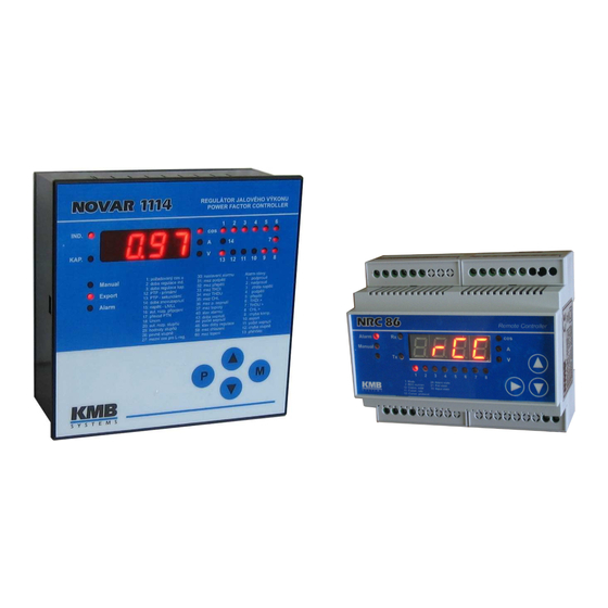
NOVAR-1xxx NRC Power Factor Controller
NRC 86 Remote Controller
Firmware v. 1.8 ( Novar ) / 1.0 ( NRC86 )
Operating Manual
10/2013
Advertisement
Table of Contents

Summary of Contents for Novar NRC86
- Page 1 Remote Controlled Target PF and Remote Controlled Outputs Compensation Systems Based on Novar Line Power Factor Controllers NOVAR-1xxx NRC Power Factor Controller NRC 86 Remote Controller Firmware v. 1.8 ( Novar ) / 1.0 ( NRC86 ) Operating Manual 10/2013...
-
Page 2: Table Of Contents
Alarm No. 15 – Remote Control Failure ..................10 Parameters 50, 51, 52 – Instrument Address, Communication Rate and Communication Protocol / NRC86 response timeout.......................11 Parameter 53 – Remote Control Mode ....................11 Parameters 80,81 – Remote Controlled Target PFs and Remote Controlled PF Serial Number .13 3. - Page 3 Logic Outputs ..........................18 3.4.3 Logic Inputs..........................19 3.4.4 Communication Interface ......................19 4. PUTTING IN OPERATION..........20 Remote Controlled Target PF Compensation Systems ..............20 Remote Controlled Outputs Compensation Systems ..............21 5. CONNECTION EXAMPLES..........23 6. NRC86 REMOTE CONTROLLER TECHNICAL SPECIFICATIONS..............26 7. MAINTENANCE, TROUBLESHOOTING .......27...
-
Page 4: Application
If, for technical or other reasons, this solution is impossible and there exists a suitable communication channel (cable or other media) between the points, the NRC86 remote controller can be used for driving the capacitor contactors. - Page 5 Novar-NRC KMB systems Detailed description of the Novar power factor controllers can be found on the manufacturers website www.kmbsystems.eu...
-
Page 6: The „Novar1Xxx Nrc" Special Version Power Factor Controllers
Default values are –0.95 / -0.97 / 1.00 / 0.97 / 0.95 , but they can be freely changed. According this setting the PFC keeps preset target PF value that is dynamically controlled by the remote controlled PF serial number from the NRC86 unit ( standard target PF value in parameter 01 has no meaning in this mode). - Page 7 Novar-NRC KMB systems Tab. 2.1 : Novar-1xxx NRC Additional and Affected Parameters name range step default comment target PF for 0.80 L ÷ 0.80 C 0.01 0.98 L in the „RCC“-mode (see par. 53), depending on the metering rate 2 parameter setting and metering rate 1 „EX.XX“...
-
Page 8: Remote Controlled Outputs - The „I/O" Mode
( i.e. a medium with no transmission delay) is used (it depends on preset communication rate and remote control mode). If usual metallic cable is used maximum distance between the PFC and the NRC86 unit is up to 1 km, but it can be nearly unlimited for suitable wireless media. -
Page 9: Parameters 30 - Alarm Setting, 40 - Alarm Status
If the metering rate 2 control is enabled and any of the RCC-modes is set simultaneously, the target PF is remote controlled by external NRC86 unit only when the metering rate 2 (tariff 2) just active. In such case, the actual value of remote controlled PF with preceding „E“ character is displayed in parameter 07 ( in the same way as in the parameter 01 when the metering rate 2 control disabled). -
Page 10: Alarm No. 15 - Remote Control Failure
When temporary interruption of the connection between the PFC and the NRC86 unit/units appears, the situation will look as follows : 1. Approximately after 20 seconds of communication link fault the PFC disconnects all of outputs step by step and it will stay in standby mode until the connection is restored. -
Page 11: Parameters 50, 51, 52 - Instrument Address, Communication Rate And Communication Protocol / Nrc86 Response Timeout
GSM/GPRS modems, LAN etc., it is necessary to set this parameter value to maximum wait time for response from the NRC86 i seconds ( in range 1 – 2 – 3 – 5 – 8 ). If the remote control mode is switched off the parameter 52 has its usual meaning – the type of communication protocol. - Page 12 NRC86 unit, all of others must be set as „slaves“, that means to passive RCC-mode marked as RCCP. As soon as the mode is set, the master PFC starts to send commands to the NRC86 unit(s). The unit (with address of 200 if more units connected) receives them, processes them and sends confirmation back to the master PFC.
-
Page 13: Parameters 80,81 - Remote Controlled Target Pfs And Remote Controlled Pf Serial Number
In the RCC-mode , co called serial number of remote controlled PF is periodically transferred from the (first) NRC86 unit to the PFC (or multiple PFCs). Its range is 1 ÷ 5 and actual value is displayed in parameter 81with identification string „ECn“; for example, if its value is 2, the... -
Page 14: Nrc 86 Remote Controller
3. NRC 86 Remote Controller The unit is designed for power factor compensation systems either with remote controlled PF or with remote controlled outputs. The unit operates in combination with special version of Novar power factor controller – Novar1xxx NRC. -
Page 15: Operation
3.2.1 Remote Controlled Power Factor (Cosinus) Mode – the „RCC“ Mode Up to five pulse signals can be connected to the NRC86 unit. A pulse of correct duration on one of inputs 1÷5 is evaluated as target PF serial number request. The unit saves the number into its memory and confirms by switching of appropriate output on ( this signal is transmitted back to the supervising system for checking ). -
Page 16: Parameter 02 - Remote Controlled Pf Serial Number
KMB(P0) / Modbus-RTU(P1) KMB(P0) remote control mode must be set to P0 (KMB) protocol set by the NRC86 unit ; indicates type of alarm : 20 alarm status -- / E / C E … external alarm (= indicates cooperating Novar1xxx NRC PFC alarm active state) C …... -
Page 17: Parameter 05 - Number Of Processed Outputs (In I/O Mode)
O1. 3.3.4 Parameter 06 – Daisy-Chain Communication Mode („Cascade“) If more than one NRC86 units connected to a PFC all of the units but the last one must be set to the daisy-chain communication mode (i.e. set to 1 1 1 1 This mode must be switched off at the last unit in the cascade , i.e. -
Page 18: Parameter 30 - Logic Inputs Status
I I I I … 1 ( active ) 3.4 Installation The NRC86 unit is designed for mounting on a DIN-35 bar. Maximum cross section area of connection wires is 2.5 square millimetres. Examples of unit wiring are shown below. -
Page 19: Logic Inputs
KMB systems 3.4.3 Logic Inputs The NRC86 unit can have up to 8 galvanically isolated logic inputs (depending on unit model). The inputs are passive – a voltage of appropriate level ( specified in technical parameters, see below ) must be applied. For direct voltage inputs the applied voltage polarity is free. The input voltages must be connected to terminals 29 ÷... -
Page 20: Putting In Operation
For remote controlled power factor the NRC86-85 24 VDC remote controller is needed. If remote controlled outputs using additional NRC86 units in cascade necessary too it is better to use the NRC86-07 230 VAC models with 7 outputs each for this task. -
Page 21: Remote Controlled Outputs Compensation Systems
I1÷ I5 inputs of the NRC86 and check response of all connected PFCs. 4.2 Remote Controlled Outputs Compensation Systems For these applications, the NRC86-07 230 VAC remote controller with 7 outputs is optimal. Up to 7 of such NRC86 units depending of number of compensation system outputs (contactors) and required spatial spread can be used. - Page 22 (No. 51) to any improper value – the PFC must during approx. 20 seconds start indicating the remote control failure alarm and switch all of its outputs off step-by-step. The NRC86 unit(s) must start to indicate the communication link failure alarm during approx. 15 seconds and after 30 seconds to disconnect all of outputs at once.
-
Page 23: Connection Examples
Novar-NRC KMB systems 5. Connection Examples Remote Controlled Target PF Compensation System with NRC86 Remote Controller Rozvaděč distributora ( AXY01, ovládací napětí 24VDC ) Napájení 24 VDC Regulace jalového výkonu (5x) 1 sec Remote Controller X113 Signalizace regulace 1: Mode... - Page 24 Novar-NRC KMB systems Remote Controlled Outputs Compensation System with Two NRC86 Remote Controllers...
- Page 25 Novar-NRC KMB systems Combined Remote Controlled Target PF and Remote Controlled Outputs Compensation System with NRC86 Remote Controllers, Wireless Remote Outputs Connection Block Diagram...
-
Page 26: Nrc86 Remote Controller Technical Specifications
Novar-NRC KMB systems 6. NRC86 Remote Controller Technical Specifications parameter NRC86 Model NRC86-85 24VDC NRC86-07 230VAC aux. supply voltage, power 18 ÷ 36 V DC, 4W 80 ÷ 275 V AC, 43 ÷ 67 Hz, 5 VA 100 ÷ 300 V DC, 5 W... -
Page 27: Maintenance, Troubleshooting
KMB systems 7. MAINTENANCE, TROUBLESHOOTING NRC86 remote controller does not require any maintenance. For reliable operation you only have to comply with the operating conditions specified and prevent mechanical damage to the instrument. In the event of the product’s breakdown, you have to return it to the supplier at their address.
Need help?
Do you have a question about the NRC86 and is the answer not in the manual?
Questions and answers