Advertisement
Quick Links
Operating, Servicing, and Safety
Manual
Model # 900
90° Hydraulic Bender
CAUTION: Read and Understand
These Operating, Servicing, and
Safety Instructions, Before Using
This Machine.
1-800-467-2464
10 Cooperative Way
Wright City, MO 63390
P.O. Box 110
Foristell, MO 63348
1-636-745-7757
Fax 1-636-745-2874
www.mittlerbros.com
REV 1 March 10 2011
Advertisement

Summary of Contents for MB 900
- Page 1 Operating, Servicing, and Safety Manual Model # 900 90° Hydraulic Bender CAUTION: Read and Understand These Operating, Servicing, and Safety Instructions, Before Using This Machine. 1-800-467-2464 10 Cooperative Way Wright City, MO 63390 P.O. Box 110 Foristell, MO 63348 1-636-745-7757 Fax 1-636-745-2874 www.mittlerbros.com...
-
Page 2: Table Of Contents
- 2 - Table of Contents · Safety Pg.3 · Hydraulic Safety Precautions Pg.4 · Hydraulic System Operation Pg.5 · Machine Set up Pg.6 · Operation Pg.7 · Math Formulas Pg.8-11 · Technical Diagram Pg.12 · Optional Equipment Pg.13-15 · Maintenance Pg.16... -
Page 3: Safety
- 3 - SAFETY The purpose of the safety section of this manual is to inform operators and maintenance personnel of the precautions to be taken while operating or servicing the machine. The following are a few basic guidelines to follow, but as with any type of machinery good judgment and a safe attitude should be applied at all times. -
Page 4: Hydraulic Safety Precautions
- 4 - HYDRAULIC SAFETY PRECAUTIONS WARNING General Operatio · All WARNING statements must be carefully observed to help prevent personal injury. · Before operating the pump, all hose connections must be tightened with the proper tools. Do not over tighten. -
Page 5: Hydraulic System Operation
- 5 - HYDRAULIC SYSTEM Pump Assembly 1. Remove the RED Plug in the pump assembly and replace with the supplied BLACK plug. This is the reservoir venting system and damage or inoperability may result if not changed out. Plug should be changed to BLACK Plug Hydraulic Hose... -
Page 6: Machine Setup
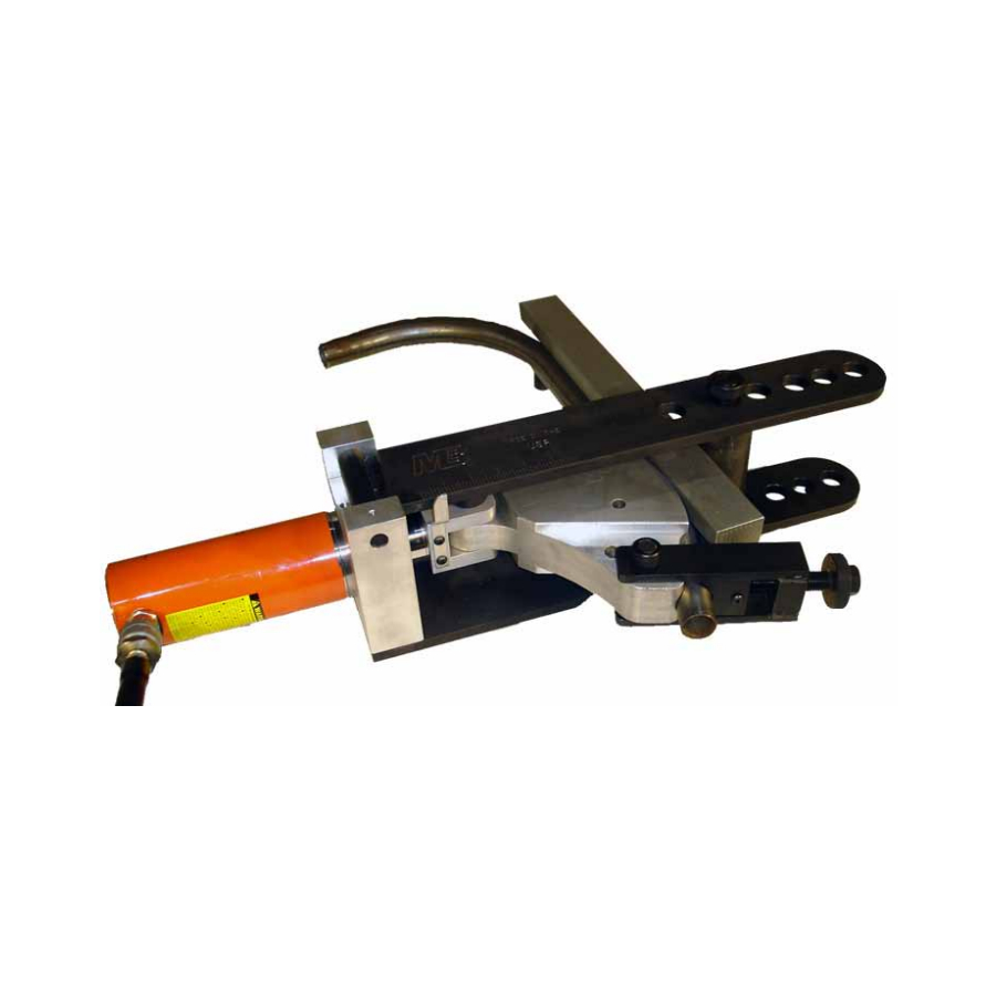
- 6 - MACHINE SETUP #3 & #15 Roller Pin #4 & #14 Upper Frame Roller #12 Follow Bar #16 Female Hydraulic Coupler #5 & #8 Clevis Pin #7 Clevis 1. Remove machine from packaging. Saddle #9 & #11 Saddle Pin 2. -
Page 7: Operation
- 7 - OPERATION Reference Scale Roller Bend Start Point Follow Bar Saddle Pin #10 Saddle #3 Tubing Through the Saddle #4 & #7 Pump Pressure #9 Release Pressure Shoe Start Point Male 1. Insert tubing into channel in the shoe, follow bar, and Hydraulic Coupler adjustable saddle. - Page 8 - 8 - CORRECTED MATHEMATICAL FORMULA FOR HYDRAULIC TUBING BENDER WHEN USING INSTRUCTION VIDEO The following formula should be used to determine the start point for each required bend. The example will be for a Double Bevel Bend L1 = 26 25 degree angle L2 = 15 65 degree angle...
- Page 9 - 9 - GAIN FACTORS Degree Degree Degree of Multiplier Multiplier Multiplier Bend of Bend of Bend .0000 .0136 .1134 .0000 .0150 .1196 .0000 .0165 .1260 .0000 .0181 .1327 .0000 .0197 .1397 .0001 .0215 .1469 .0001 .0234 .1544 .0003 .0254 .1622 .0003 .0276...
- Page 10 -- 10 -- DEVELOPED LENGTH DEVELOPED LENGTH = .0175 X DEGREE OF BEND X RADIUS EXAMPLE: FIND THE DEVELOPED LENGTH OF A 70 DEGREE BEND USING AN 8 INCH RADIUS. DEVELOPED LENGTH = .0175 X 70 X 8 = 9.80 OR 9 13/16 ________________________________________________________________________________________ ________________________________________________________________________________________ ________________________________________________________________________________________...
- Page 11 -- 11 -- TABLE FOR OFFSET MULTIPLIER Degree Degree Multiplier Multiplier Bend Bend 57.30 2.37 28.65 2.28 19.11 2.20 14.33 2.13 11.47 2.06 9.57 2.00 8.21 1.94 7.18 1.89 6.39 1.84 5.76 1.79 5.24 1.74 4.81 1.70 4.45 1.66 4.13 1.62 3.86 1.59...
- Page 12 -12- ITEM NO. QTY. PART NO. 1 900-003 Cylinder Mount Block 1 900-002 Lower Frame 1 900-005 Upper Frame 1 900-004 Shoe Clevis 1 900-007 Follow Bar Roller 1 900-018 Scale Pointer 1 900-502 Hydraulic Cylinder 1 900-008-C Hinge Pin...
-
Page 13: Optional Equipment
Adjustable Saddle, Small 5/8" to 1-3/8" 2500-301 Adjustable Saddle, Medium 1-1/2 to 1-3/4 2500-302 Adjustable Saddle, Large 2" OD Pumps 900-504-6 Air Hydraulic Pump, 6' Hose & Fitting 900-508-6 Electric Hydraulic Pump, Hose & Fittings 6' 900-D Digital Read Out for 90° Hydraulic Tube Bender... - Page 14 -14- Bend Protractors 2100-4 4" Protractor Assembly 2100-5 5" Protractor Assembly 2100-6 6" Protractor Assembly 2100-7 7" Protractor Assembly 2100-8 8" Protractor Assembly 2100 4" Thru 8" Protractor Set...
- Page 15 -15- BEND-TECH EZ Designed for simple 2d parts! 900-510 Bend-Tech EZ Software BEND-TECH EZ-3D Designed for 3d bending, with 360 degree part rotation! 900-511 Bend-Tech EZ-3D Software BEND-TECH PRO Full 3d Assembly & Manufacturing Instructions, plus all EZ features! 900-512...
-
Page 16: Maintenance
-16- MAINTENANCE Inspecting The Hydraulic Fluid Level Check the fluid level in the reservoir after every 10 hours of use. Drain and replenish the reservoir with Power Team hydraulic fluid after every 300 hours of use approximately. Air Hydraulic Pump Electric Hydraulic Pump For pumps with a 105 cubic inch (1.71) reservoir capacity For pumps with a 2 gallon (7.61) reservoir capacity...
Need help?
Do you have a question about the 900 and is the answer not in the manual?
Questions and answers