Table of Contents
Advertisement
Available languages
Available languages
Our Customer Service staff are ready to provide
assistance. If a part is damaged or missing, replacement
parts can be shipped from our facility.
For immediate help with assembly, or for additional
product information, call our toll-free
number: 1-877-270-7772.
You will need this manual for safety instructions, operating procedures, and warranty.
Put it and the original sales invoice in a safe, dry place for future reference.
Vous aurez besoin de ce guide pour les instructions de sécurité, les procédures d'utilisation et la garantie.
*Products may differ slightly from those pictured *Les produits l'emballage peuvent différer
Model / Modèle:
QUESTIONS? 1-877-270-7772
C
SAVE THIS MANUAL
CONSERVEZ CE GUIDE
Conservez-le dans un endroit sûr et sec pour référence future.
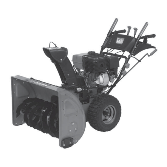
GSE3226STG / GSE5230STG
Gas Snowthrowers
General Instruction Manual
Souffleuse à essence
Manuel d'instruction général
Notre personnel du service à la clientèle sera prêt à
fournir assistance. Si une pièce est endommagée ou
manquante, des remplacements seront expédiés de notre
usine.
Pour de l'aide immédiate avec l'assemblage, ou pour des
informations additionnelles sur le produit, appeller notre
numéro sans frais nord-américain : 1 (877)
840-0840.C
Advertisement
Chapters
Table of Contents
Troubleshooting

Summary of Contents for P3 International GSE3226STG
- Page 1 GSE3226STG / GSE5230STG Model / Modèle: Gas Snowthrowers General Instruction Manual Souffleuse à essence Manuel d’instruction général QUESTIONS? 1-877-270-7772 Notre personnel du service à la clientèle sera prêt à Our Customer Service staff are ready to provide assistance. If a part is damaged or missing, replacement fournir assistance.
-
Page 2: Table Of Contents
TABLE OF CONTENTS Important Safe Operating Practices .............. p.2 Assembly Instructions ................... p.5 Specifications ....................p.8 Functional Description ................... p.8 Operating Procedures ................... p.10 Adjustment ....................p.14 Maintenance ....................p.16 Servicing ......................p.17 Warranty ...................... -
Page 3: Important Safe Operating Practices
IMPORTANT SAFE OPERATING PRACTICES 3. Never allow children under 14 years of age to operate this machine. Children 14 years old and over should read and understand the operating instructions and safety rules in this manual and should be trained and supervised by a parent. -
Page 4: Maintenance And Storage
IMPORTANT SAFE OPERATING PRACTICES 6. Do not operate machine while under the influence of alcohol or drugs. 7. Muffler and engine become hot and can cause bums. Do not touch. 8. Exercise extreme caution when operating on or crossing a gravel surface. 9. -
Page 5: Assembly Instructions
IMPORTANT SAFE OPERATING PRACTICES WARNING: Restrict the use of this power machine to persons who read, understand and follow the warnings and instructions in this manual and on the machine. WARNING: The warnings, cautions, and instructions detailed in this manual cannot cover all possible conditions and situations that occur. - Page 6 ASSEMBLY INSTRUCTIONS Fig.3 ASSEMBLE THE CABLES FOR AUGER CONTROL AND DRIVE CONTROL The cable for Auger Control is located at the left side while that for Drive Control at the right side. To assemble the cable for Auger Control, slide the cable connector up over the end of the nut and then secure the nut with wrench.
- Page 7 ASSEMBLY INSTRUCTIONS ASSEMBLE THE DISCHARGE CHUTE 1. Loosen and remove the butterfly bolt and flat washer from the chute chassis. Put the discharge chute into the chute chassis as shown (Fig.4) Discharge chute Chute chassis Fig.4 3. Align the hole of the discharge chute with the hole of Chute chassis, fasten the butterfly bolt and flat washer previously removed (Fig5).
-
Page 8: Specifications
SPECIFICATIONS GSE3226STG GSE5230STG 2 stage snow clearance 2 stage snow clearance Motor: 27-degree inclined single cylinder Motor: 27-degree inclined single cylinder , four-stroke gasoline engine , four-stroke gasoline engine Bore x stroke: 70 x 54 ... - Page 9 FUNCTIONAL DESCRIPTION WARNING: Read, understand, and follow all instructions and warnings on the machine and in this manual before operating. IMPORTANT Always release drive control before changing speeds. Drive Control The drive control is located on the right handle. Squeeze the drive control to engage the wheel drive. Release to stop.
- Page 10 FUNCTIONAL DESCRIPTION Chute Directional Control The chute directional control is located on the left side of the snow thrower. See Figure 6 To change the direction in which snow is thrown, turn chute directional control as follows: . Crank clockwise to discharge to the left. .
-
Page 11: Operating Procedures
OPERATING PROCEDURES Headlight The headlight is on when the headlight knob on the right side of the panel is pressed to “ON” position and wil be off when the knob is pressed to “ OFF” position, See Fig.6 Heated handle ( only for GSE5230STG ) The heated handle has two settings –... -
Page 12: To Stop Engine
If you have a grounded three-prong receptacle, proceed as follows, 1. Push Primer three (3) times, making sure to cover vent hole when pushing. 2. Move CHOKE/RUN lever on the engine to “ CHOKE” position. 3. Connect power cord to switch box on engine. Plug the other end of power cord into a three-hole, grounded 120 volt AC receptacle. - Page 13 OPERATING PROCEDURES To Engage Wheel Drive ● With the engine running near top speed, move the shift lever into one of the six FORWARD positions or two REVERSE positions, Select a speed appropriate for the snow conditions that exist. ● Squeeze the auger control and the augers will turn. Release it and the augers will stop. ●...
-
Page 14: Operating Tips
OPERATING PROCEDURES CLEAN-OUT TOOL The clean-out tool is conveniently fastened to the rear of the auger housing with a mounting clip. Should snow and ice lodge itself in the chute assembly during operation, proceed as follows to safely clean the chute and chute opening: 1. -
Page 15: Adjustment
ADJUSTMENT WARNING: NEVER attempt to make any adjustments while the engine is running, except where specified in the operator’s manual. AUGER CONTROL Refer to Auger Control Test in the Operating Procedures section to adjust the auger control. DRIVE CONTROL AND SHIFT LEVER To check the adjustment of the drive control and shift lever, proceed as follows: ... -
Page 16: Shift Rod Adjustment
ADJUSTMENT NOTE: If you placed plastic film under the gas cap, be certain to remove it before operating the snowthrower. SHIFT ROD ADJUSTMENT To adjust the shift rod, proceed as follows: ● Remove the hairpin clip and slide the shift rod connector up, to separate the upper shift rod from the lower shift rod. -
Page 17: Maintenance
ADJUSTMENT CARBURETOR Minor carburetor adjustment may be required to compensate for differences in fuel, temperature, altitude and load. Refer to the separate engine manual packed with your unit, for carburetor adjustment information. MAINTENANCE WARNING: Before lubricating, repairing, or inspecting, disengage all controls and stop engine. -
Page 18: Servicing
MAINTENANCE Auger Shaft At least once a season, remove the shear pins on the auger shaft. Spray lubricant inside the shaft and lubricate the plastic auger bearings at least once a season. See Figure15. Auger Bearings Every season lubricate the auger bearings with light oil. Drive and Shifting Mechanism Lubricate at least once a season or after 25 hours of operation. -
Page 19: Warranty
SERVICING OFF- SEASON STORAGE WARNING: Never store the machine or fuel container indoors where there is an open flame, spark, or pilot light such as on water heater, furnace, clothes dryer, or other gas appliance. WARNING: Drain fuel into an approved container outdoors, away from an open flame. -
Page 20: Troubleshooting
LIMITED WARRANTY GOSS makes no further warranties or representations, express or implied except those contained herein. No represen- tative dealer is authorized to assume any other liability regarding the Snowthrower. The duration of the implied limited warranty granted under any Provincial law, including warranties of merchantability and fitness for particular purpose are limited in duration to the express duration provided for herein. - Page 22 TABLE DES MATIÈRES Schéma ......................p.23 Liste des pièces ..................... p.26 Opérations sécuritaires importantes .............. p.28 Consignes d’assemblage ................p.32 Fiche technique ..................... p.35 Descriptions fonctionnelle ............p.35 Utilisation ....................... p.37 Ajustement ....................p.41 ...
-
Page 23: Opérations Sécuritaires Importantes
OPÉRATIONS SÉCURITAIRES IMPORTANTES AVERTISSEMENT : Certaines consignes de sécurité de base doivent toujours être respectées lors de l’utilisation d’un appareil à essence afin de réduire les risques de blessure ou de dommage. Avant d’employer ce produit, lisez tous les avertissements et instructions. Conservez ce manuel d’instructions pour référence future. - Page 24 OPÉRATIONS SÉCURITAIRES IMPORTANTES Ne remplissez jamais le réservoir de carburant au-dessus du niveau maximum. Remplissez-le à 1,25 cm (1/2 po) au-dessous du capuchon pour fournir de l’espace pour l’expansion du carburant. g. Replacez le capuchon et serrez solidement. h. Si vous renversez de l’essence, essuyez le moteur et la souffleuse, déplacez la et attendez 5 minutes avant de la démarrer à...
- Page 25 OPÉRATIONS SÉCURITAIRES IMPORTANTES ENTRETIEN ET ENTREPOSAGE 1. Ne trafiquez jamais les dispositifs de sécurité. Vérifiez leur opération appropriée régulièrement. Référez-vous aux sections de réglage d’entretien de ce manuel. 2. Avant le nettoyage, la réparation, ou l’inspection de la machine désengagez toutes les commandes et arrêtez le moteur.
-
Page 26: Consignes D'assemblage
CONSIGNES D’ASSEMBLAGE NOTE: La référence à droite ou à gauche de la souffleuse à neige est déterminée à partir de derrière l’unité en position de l’opérateur. La « position de l’opérateur » est définie comme se tenant directement derrière la souffleuse à neige, faisant face au panneau de poignée. - Page 27 CONSIGNES D’ASSEMBLAGE Support supérieur du boulon de chariot contrôle de chute rondelle plate Tige d'embrayage supérieure Tige de contrôle de chute supérieure Écrou papillon Connecteur de tige d'embrayage goupille Tige d'embrayage inférieure Boulon de chariot Tige de chute inférieure ASSEMBLAGE DES CÂBLES POUR LA COMMANDE DE FOREUSE ET LA COMMANDE D’ENTRAÎNEMENT Le câble pour la commande de foreuse est situé...
- Page 28 CONSIGNES D’ASSEMBLAGE Assemblage de la chute de déchargement 1. Dévissez et retirez les boulons papillons et la rondelle plate de du cadre de la chute. 2. Placez la chute dans le cadre tel qu'illustré. (Fig. 4) 3. Allignez les trous de la chute et du cadre, et fixez les boulons papillons et la rondelle plate. (Fig. 5) Chute d'évacuation support de chute Fig.4...
-
Page 29: Fiche Technique
FICHE TECHNIQUE GSE3226STG GSE5230STG Déblaiement de neige à 2 phases Déblaiement de neige à 2 phases Moteur à essence, simple cylindre de Moteur à essence, simple cylindre de 27 degrés, 4 temps 27 degrés, 4 temps Rapport course/alésage: 70 x 54... - Page 30 DESCRIPTION FONCTIONNELLE AVERTISSEMENT : Lisez, comprenez et suivez toutes les instructions et avertissements sur la machine et dans ce manuel avant l’opération. IMPORTANT : Libérez toujours la commande d’entraînement avant de changer de vitesses. LEVIER D'ENTRAINEMENT La commande d’entraînement est située sur la poignée de droite. Serrez la commande d’entraînement pour engager la commande de roue.
- Page 31 FUNCTIONAL DESCRIPTION LEVIER DE CONTRÔLE Le levier de contrôle est situé sur le moteur. Il contrôle la vitesse du monteur et arrêtera le moteur s'il est poussé complètement vers la droite. (position "stop") Voir fig. 8 Ajout d'huile moteur Clé de démarrage amorceur Bouchon d'essence...
- Page 32 UTILISATION DE VOTRE SOUFFLEUSE À NEIGE POIGNÉE CHAUFFANTE (MODÈLE GSE5230STG) La poignée chauffant a 2 réglages - position "I" à 40-50 C et la position "II" à 50-60 C. Sélectionnez la position appropriée selon votre intérêt. AVANT LE DÉMARRAGE AVERTISSEMENT : Lisez, comprenez, et suivez tous les instructions et avertissements sur la machine et dans ce manuel avant l’opération.
-
Page 33: Utilisation
UTILISATION Démarreur électrique Vérifiez que votre câblage de maison est un système à trois fils mise-à-terre. Demandez à un électricien autorisé si vous n’êtes pas certain. Si votre système de câblage de maison n’est pas un système à trois fils mise-àterre, n’employez pas ce démarreur électrique sous aucune condition. - Page 34 UTILISATION POUR ARRÊTER LE MOTEUR Laissez fonctionner le moteur quelques minutes avant de l’éteindre pour aider à sécher l’humidité du moteur. Pour aider à prévenir un gel du démarreur, procédez comme suit : DÉMARREUR ÉLECTRIQUE Reliez l’extension électrique dans la boîte de commutateur (Y fig.10) sur le moteur, puis au réceptacle de 120 volts.
- Page 35 UTILISATION Vérifiez l’ajustement de la commande de foreuse comme suit : Quand la commande de foreuse est libérée et dans la position Contrôleur désengagé (vers le haut), le câble devrait être peu tendu. Mais, il ne de foreuse devrait pas être serré. Dans un secteur bien ventilé, mettez en marche le moteur de la souffleuse à...
-
Page 36: Ajustement
UTILISATION Projetez la neige avec un vent arrière autant que possible. Votre trajet devrait se chevaucher légèrement à chaque passe. Placez les chaussures de dérapage 6 mm (1/4 po) au-dessous de la lame du dessous de la boîte pour l’utilisation normale. •... - Page 37 AVERTISSEMENT : Vidangez l’essence hors du réservoir de la souffleuse à neige, ou placez une feuille de plastique sous le capuchon de gaz pour éviter le débordement AVANT DE faire l’ajustement. Penchez la souffleuse à neige vers l’avant, lui permettant de se reposer sur la boîte de la foreuse (B, fig.11).
-
Page 38: Entretien
AJUSTEMENT IMPORTANT : Assurez-vous de vérifier l’ajustement de la tige d’embrayaye comme décrit sous les ajustements finaux 1 à 6 dans la section Consignes d’Assemblage, avant d’utiliser la souffleuse à neige. CHAUSSURES DE DÉRAPAGE L’espace entre la boîte de la foreuse et la terre peut être ajusté. Pour le déblaiement de neige proche du sol ou sur une surface douce, montez ... -
Page 39: Entretien Mécanique
ENTRETIEN Axe de vitesse Lubrifiez l’axe de vitesse avec la graisse 6-en-1 du moins une fois par saison ou après toutes les 25 heures d’utilisation (disponible dans les magasins de pièces automotives) IMPORTANT : Gardez toutes les graisse et pétrole loin du caoutchouc de la roue d’entraînement et de la plaque de frottement en aluminium. - Page 40 ENTRETIEN MÉCANIQUE FOREUSES Goupille de cisaillement Goupille fendue écrou de boitier Les foreuses sont fixés à l’axe avec deux goupilles de cisaillement ( fig.16 ) et goupilles (fig.16 ). Si vous frappez un objet étranger dur ou bloquez les foreuses avec de la glace, la souffleuse à...
-
Page 41: Garantie
ENTRETIEN MÉCANIQUE 4. Essuyez l’équipement avec un chiffon huilé pour empêcher la rouille. 5. Enlevez la bougie d’allumage et versez une once d’huile à moteur par le trou de bougie d’allumage dans le cylindre. Couvrez le trou de bougie d’allumage avec un chiffon. -
Page 42: Dépannage
DÉPANNAGE PROBLÈME CAUSE SOLUTION Le moteur ne démarre pas Réservoir de carburant vide, ou Remplissez réservoir d’essence propre carburant dénaturé. et fraîche. Le carburant devient dénaturé après trente jours. Ligne de carburant bloquée. Nettoyez la ligne de carburant. Le bouton “CHOKE/RUN” n’est pas en Déplacez le bouton à... - Page 43 GSE3226STG Engine Manual Guide de Utilisateur Moteur IMPORTANT: BEFORE OPERATING ENGINE – AVANT D’UTILISER LA POMPE À EAU Failure to follow instructions may result in serious injury or death Une mauvaise utilisation de l’appareil porrait causer des blessures graves et entraîner la mort.
- Page 44 CONTENTS Notice 1. General Information 2. Components & Principle 3. Safety Instruction 4. Specifications 5. Operation 6. Trouble Shooting 7. Maintenance & Servicing 8. Storage & Transportation...
-
Page 45: Notice
Notice Read this manual carefully before operation. All rights reserved. Copy or transcribe this manual or any part of this manual is strict prohibited without written authorization. Please pay attention to the following safety labels that indicates personal safety is required. :WARNING indicates death, personal injury and/or property damage may occur if instructions are not followed carefully :CAUTION indicates personal injury and/or property damage might occur if... -
Page 46: General Information
1. General Information This manual applies to 165/170 series engines. Please read this manual carefully prior to operating the engine. The engine is single cylinder, 4-stroke, forced cooling, OHV engine with transistor ignition and oil alarm system. It was carefully engineered to provide excellent performance when properly operated and maintained. -
Page 47: Components & Principle
2. Components & Principle 1. Fuel tank 2. Safety label 3. Drain bolt 4. output shaft 5. Muffler guard 6. Control panel 7. Fuel gap 8. Cylinder head cover 9. Starter 10. Starter handle... -
Page 48: Safety Instruction
3. Safety Instruction ● The engine shall be operated only by qualified person. ● Exhaust gases contain carbon monoxide, an odorless and deadly poison. Do not use indoors ● For personal safety, please pay attention to the following labels: ● DO NOT touch muffler, cylinder or other hot parts which may cause burns. ●... - Page 49 ● Never remove gas cap or add fuel or oil while the engine is hot or running. Allow engine to cool at least two minutes before refueling. ● Never over fill fuel tank. If gasoline is spilled, wipe it off the engine. ●...
-
Page 50: Specifications
4. Specifications Model 165F/P 170F/P B(mm)×S(mm) 65×54 70×54 179.2 207.8 Displacement, cm³ Compress Ratio 8.5:1 8.5:1 Fuel Consumption Rate, g/(kW·h) Oil Consumption Rate, g/(kW·h) 6.8 g/(kw.h) Idle Speed, r/min 1440±144 1440±144 IN: 0.10 ∼0.15, EXH: 0.15 ∼0.20 Valve Lash, mm Conformance with GB15739-1995 Noise Limit Test standard: GB/T1859-2000... -
Page 51: Operation
5. Operation 1. Before Operation No fuel or oil in engine. Fill fuel and oil before using. 1.1 Check oil level. a. Remove dipstick and clean it. b. Insert the dipstick into oil filler neck as shown in figure 5-1, but do not screw it in, then remove it out and check oil level. - Page 52 Oil is a major factor affecting performance and service life. 4-stroke automotive detergent oil SAE 5W-30 is recommended for this wintertime engine. Figure 5-1 - Dipstick - Upper limit - Lower limit...
- Page 53 1.2 Check fuel level. a. Remove the fuel cap. b. Add unleaded gasoline to the bottom of the fuel level limit (A red plate in the neck of the fuel tank). c. Wipe up spilled fuel and reinstall the cap. 1.
- Page 54 Refuel only outdoors. Gasoline is poisonous, be careful not to touch it or inbreathe its vapor. 2. Starting Engine 2.1 Press the primer three times for an interval of 1 second. 1 - primer Figure 5-3 2.2 Put choke lever to a suitable position 2.3 Move throttle control lever to a suitable position 2.4 Pull starter handle lightly until you feel resistance, then pull briskly.
- Page 55 2.6 Let engine run a few minutes at idle speed to warm up before operating. 1 - throttle control lever 2 - throttle “open” 3 - throttle “close” 4 – starter 5 - choke “close” Figure 5-4...
- Page 56 1 - choke lever 2 - choke “open” Figure 5-5 Do not uses choke if engine is warm or the ambient temperature is very high. Do not allow the starter grip to snap back against the engine. Return it gently. For your health, do not face to exhaust outlet while engine is running.
- Page 57 3. Stop Engine/After Use IN AN EMERGENCY Move throttle control lever to “close” position or draw out engine switch immediately. 1 - engine switch Figure 5-6...
- Page 58 Do not stop engine with load in normal condition. 4. Adjustment Each adjustable part is set at right range and no more adjustment is needed. You can reset it as following instruction if necessary: 4.1 Valve lash adjustment Intake: 0.10—0.15mm; Exhaust: 0.15—0.20mm. a.
- Page 59 Gauge Valve Rocker Lock nu Adjustin g nut Unscrew adjust nut to i ncreasing valve lash Screw adjust nut decrea sing valve lash Fig 7-6 Fig 7-7 4.1 Governor system adjustment (tension spring, governor lever and bracket) a. Remove fuel tank. b.
-
Page 60: Trouble Shooting
6. Trouble Shooting 1. Difficult to start Problem Cause Solution Deposit existing Clean or replace Adjust to 0.7 ∼ 0.8mm Spark plug Spark plug gap issue Insulation damaged Replace spark/ignition Damaged Ignition module Replace Ignition module Other parts Flywheel magnetic issue Replace flywheel Fuel flooded Dry spark plug... - Page 61 2. Unconventional running Problem Cause Solution Chock not open Open choke High back pressure at muffler Replace muffler Worn/torn moving parts Check/replace Low speed/lack of Governor system setting issue Adjust power Poor ignition Replace ignition module or flywheel Valve lash issue Adjust Deposition in combustion chamber Clean...
-
Page 62: Maintenance & Servicing
7. Maintenance & Servicing Scheduled maintenance will guarantee your engine performance in its life. Check following table for detailed information. Scheduled maintenance list Regular Before Monthly or Every 3 Every 6 Annually service period each use every 25Hrs months or months or or every 50Hrs... -
Page 63: Storage & Transportation
8. Storage & Transportation Allow engine to cool before transportation or storage. Fasten engine during transportation to reduce the possibility of fuel leak. When the engine will not be use for long time, prepare it for storage with the following steps. 1. - Page 64 1-877-270-7772 6226 Danville Road Mississauga, ON, L5T 2H7...
Need help?
Do you have a question about the GSE3226STG and is the answer not in the manual?
Questions and answers
Hi ; I purchased a used P3 GSE5230STG snowblower and I'm looking for the chute chassis and wondering if there are any places to get parts in Canada . Any help would be greatly appreciated . Thanks , Vern
Replacement parts for the P3 International GSE5230STG snowblower can be shipped from the facility. For assistance, call the toll-free number 1-877-270-7772.
This answer is automatically generated