Advertisement
Quick Links
GENERAL INFORMATION
The PS24 power supply module is an accessory for Ademco control
panels intended for use in commercial fire installations. The PS24
has two triggerable 24VFW (full wave rectified, unfiltered), 1.7 amp
outputs that can either provide 24VFW auxiliary power, or can
convert up to two control panel 12VDC EOLR supervised bell circuit
outputs to 24VFW EOLR supervised bell outputs.
Each of the PS24 outputs, labeled OUTPUT A and OUTPUT B, has
a corresponding controlling input, labeled INPUT A and INPUT B,
respectively. Negative voltages applied to INPUT A and INPUT B
are passed through to the associated output, allowing the control
panel to supervise bell circuit wiring connected to that output (as
required for installations which use the output for 24VFW, EOLR-
supervised bell circuit operation). Applying positive voltages of 9.5 –
14VDC to INPUT A and INPUT B produces 24VFW at the respective
output terminals.
For installations which require 24VFW auxiliary power, you must
wire INPUT A and/or INPUT B to the control panel's 12VDC auxiliary
power terminals so that the associated PS24 output remains
activated continuously. For installations which require 24VFW
EOLR supervised bells, you must wire INPUT A and /or INPUT B to
the controls panel's 12VDC EOLR supervised bell terminals.
Primary power for the PS24 power supply module is supplied by a
1451-24 transformer, which consists of an AC power trans former
and a manually resettable circuit breaker mounted inside a
protective enclosure. The 1451-24 transformer has two secondary
windings – a 30VAC/188VA winding which is used to power the
PS24 module, and a 18VAC/72VA winding which is used to power
the control panel. The PS24 module monitors its connection to the
1451-24 and can report a low AC condition to the control panel via
one of the control panel's EOLR supervised zones.
Notes:
1. The 1451-24 transformer is not supplied with the PS24 unless
part of a kit (see Note 2).
2. Complete control panel kits are available, consisting of the
control panel, PS24 module, and 1451-24 transformer. For
example, a 5140XM control panel kit is available under part
No. 5140XM–24ADA, and consists of the 5140XM control
panel, PS24 module, 1451-24 transformer, and a few other
peripheral devices.
Secondary power for the PS24 power supply module is supplied by
a pair of 12VDC lead-acid (gel cell) batteries rated at 7AH minimum,
17.2AH maximum. Both batteries connect directly to the PS24
module which internally configures them to provide 24V back-up
power for its outputs, and 12V back-up power for the control panel.
The PS24 module charges and tests these batteries, and can report
a low or disconnected battery condition to the control panel via one
of the control panel's EOLR supervised zones.
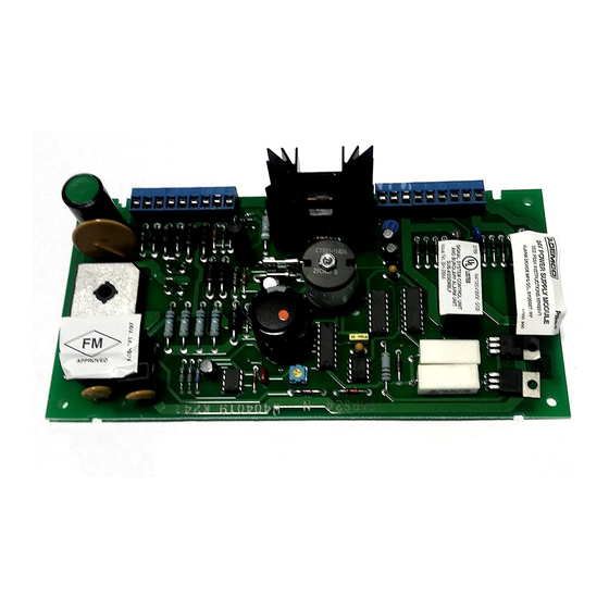
MOUNTING
The PS24 module is designed to mount inside the control panel
enclosure.
Referring to Figure 1, attach the PS24 PCB to the metal bracket
(supplied) using the four #6 sheet metal screws (supplied). Then,
clip the PS24 bracket onto the left sidewall of the control panel
enclosure as shown in Figure 2. This method of mounting leaves
room in the control panel's enclosure for the panel/module back-up
batteries.
Note: The control panel enclosure should be mounted to the wall
before attempting to install the PS24 module because the
PS24 will block access to the control's left mounting hole.
INSTALLATION
INSTRUCTIONS
POWER SUPPLY MODULE
18
17
16
15
14
13
12
11
10
9
8
7
6
5
4
3
2
1
TIE WRAP HOLE
(SEE FIGURE 2)
Mounting the PS24 PCB to the Metal Clip Bracket
MOUNT PS24 PCB/METAL
BRACKET ASSEMBLY AS SHOWN
BEFORE MOUNTING THE PS24:
• MOUNT CONTROL PANEL
ENCLOSURE TO WALL
• REMOVE CONTROL PANEL
ENCLOSURE DOOR
RUN AC POWER WIRES
THROUGH THIS KNOCKOUT.
ROUTE THESE WIRES AWAY
FROM OTHER CONTROL PANEL
WIRING SO AS TO MAINTAIN
AT LEAST 1/4" SPACING.
SECURE THESE WIRES BY TIE
WRAPPING THEM TO THE
PS24's TIE WRAP HOLE.
Mounting the PS24 Inside the Control Panel Enclosure
BATTERY CAPACITY CALCULATIONS
The PS24 module requires connection of two 12VDC lead acid (gel cell)
batteries rated at 7AH minimum/17.2AH maximum. The PS24 configures
these batteries to provide 24V back-up power for it's 24V outputs and 12V
back-up power for the control panel. See the CONNECTIONS AND
POWER UP PROCEDURES section for battery connection details.
UL NOTE:
UL requires that the battery's capacity be sized for 24 hours of standby
time, followed by 5 minutes of alarm time for commercial fire installations
or 15 minutes of alarm time for commercial fire/burglary installations.
Appropriate battery capacity can be calculated using the worksheets on
the next page.
1. Fill in the total control panel standby and alarm currents in the
worksheet below. These totals must include the control panel's PCB
currents as well as the currents drawn from the control panel's
auxiliary power and bell power outputs. Refer to the control panel's
installation instructions to determine these currents.
N7499V1 9/95
PS24
METAL CLIP BRACKET
PS24 PCB
(COMPONENT SIDE SHOWN)
#6 SHEET
METAL SCREWS
Figure 1.
DO NOT USE THIS KNOCKOUT
18
17
16
15
14
13
12
11
10
CONTROL
9
PANEL
8
7
PCB
6
5
4
3
2
1
12V
12V
BATTERY
BATTERY
Figure 2.
CONTROL
PANEL
ENCLOSURE
Advertisement

Subscribe to Our Youtube Channel
Related Manuals for ADEMCO PS 24

Summary of Contents for ADEMCO PS 24
-
Page 1: Power Supply Module
POWER SUPPLY MODULE GENERAL INFORMATION METAL CLIP BRACKET The PS24 power supply module is an accessory for Ademco control panels intended for use in commercial fire installations. The PS24 has two triggerable 24VFW (full wave rectified, unfiltered), 1.7 amp outputs that can either provide 24VFW auxiliary power, or can... - Page 2 BATTERY CAPACITY CALCULATIONS (Cont’d) Fill in the Total PS24 MODULE Load Worksheet, below, to deter - Select 12-volt batteries from the BATTERY SELECTION TABLE mine the PS24’s total standby and alarm current loading. Then use having capacities which are greater than, or equal to, the calculated the BATTERY CAPACITY CALCULATION WORKSHEET to capacities.
- Page 3 COMPATIBLE UL LISTED INDICATING DEVICES TABLE NOTE: Use UL listed devices rated for 21–30VFW. Horn/Strobes: Strobes (continued): System Sensor MASS2415ADA Gentex GXS–4–15–1 System Sensor MASS2475ADA Gentex GXS–4–1575 System Sensor MASS24110ADA Gentex GXS–4–110–1 System Sensor MASS241575ADA BELL CIRCUIT WIRE RUN LENGTH TABLE. Wheelock MT-24-LS–VFR &...
- Page 4 18 months from the date stamp con trol on the product or, for products not having an Ademco date stamp, for 12 months from date of original purchase unless the installation instructions or catalog sets forth a shorter period, in which case the shorter period shall apply.
Need help?
Do you have a question about the PS 24 and is the answer not in the manual?
Questions and answers