
Related Manuals for Polymetron 9210

Summary of Contents for Polymetron 9210
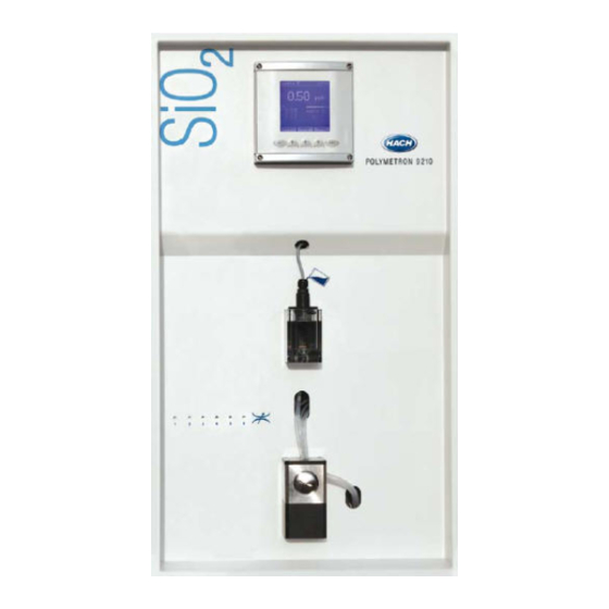
- Page 1 221=192=010 POLYMETRON Model 9210 Silica Analyzer USER MANUAL May 2009, Revision K...
-
Page 3: Table Of Contents
Table of Contents ......................5 Section 1 General Information 1.1 Disclaimer ............................ 5 1.2 Safety information ........................5 1.2.1 Use of hazard information ....................5 1.2.2 Safety recommendations ....................5 1.2.3 Service and repairs ......................6 1.2.4 Precautionary labels......................6 1.3 Product recycling information....................... - Page 4 Table of Contents 5.4 Analyzer menu overview ......................36 ........................37 Section 6 System Setup 6.1 Menu overview ...........................37 6.1.1 Time ..........................37 6.1.2 Display..........................38 6.1.3 Code..........................38 6.1.4 Soft issues.........................39 6.1.5 Default values........................39 6.1.6 mA adjustments.........................39 6.1.7 Factory ..........................40 ........................41 Section 7 User Setup 7.1 Measure menu overview ......................41 7.1.1 Measuring mode........................41 7.1.2 Grab sample........................42...
- Page 5 Table of Contents 9.14 Solenoid valves........................67 9.15 Relays ............................67 9.16 Logical inputs ........................... 67 9.17 Preparation of the tubes for insertion in the fast connectors............ 68 ......................69 Section 10 Troubleshooting 10.1 Possible sources of the problem ....................69 10.2 Possible solutions ........................
- Page 6 Table of Contents...
-
Page 7: Section 1 General Information
Section 1 General Information 1.1 Disclaimer The information in this manual has been carefully checked and is believed to be accurate. However, Hach Lange assumes no responsibility for any inaccuracies that may be contained in this manual. In no event will Hach Lange be liable for direct, indirect, special, incidental, or consequential damages resulting from any defect or omission in this manual, even if advised of the possibility of such damages. -
Page 8: Service And Repairs
General Information 1.2.3 Service and repairs None of the analyzer’s components can be serviced by the user. Only personnel from Hach Lange or its approved representative(s) is (are) authorized to attempt repairs to the system and only components formally approved by the manufacturer should be used. Any attempt at repairing the analyzer in contravention of these principles could cause damage to the analyzer and corporal injury to the person carrying out the repair. -
Page 9: Product Recycling Information
General Information 1.3 Product recycling information ENGLISH Electrical equipment marked with this symbol may not be disposed of in European public disposal systems after 12 August 2005. In conformity with European local and national regulations (EU Directive 2002/96/EC), European electrical equipment users must now return old or end-of-life equipment to the manufacturer for disposal at no charge to the user. -
Page 10: General Information
General Information SVENSKA Elektronikutrustning som är märkt med denna symbol kanske inte kan lämnas in på europeiska offentliga sopstationer efter 2005-08-12. Enligt europeiska lokala och nationella föreskrifter (EU-direktiv 2002/96/EC) måste användare av elektronikutrustning i Europa nu återlämna gammal eller utrangerad utrustning till tillverkaren för kassering utan kostnad för användaren. Obs! Om du ska återlämna utrustning för återvinning ska du kontakta tillverkaren av utrustningen eller återförsäljaren för att få... -
Page 11: Product Disposal
General Information 1.4 Product disposal Note: The following only applies to European customers. Hach Lange is committed to ensuring that the risk of any environmental damage or pollution caused by any of its products is minimized as far as possible. The European Waste Electrical and Electronic Equipment (WEEE) Directive (2002/96/EC) that came into force on August 13 2005 aims to reduce the waste arising from electrical and electronic equipment;... -
Page 12: Restriction Of Hazardous Substances (Rohs)
General Information 1.5 Restriction of hazardous substances (RoHS) The European Union RoHS Directive and subsequent regulations introduced in member states and other countries limits the use of six hazardous substances used in the manufacturing of electrical and electronic equipment. Currently, monitoring and control instruments do not fall within the scope of the RoHS Directive, however Hach Lange has taken the decision to adopt the recommendations in the Directive as the target for all future product design and component purchasing. -
Page 13: Section 2 Specifications
Section 2 Specifications 2.1 Technical specifications Specifications are subject to change without notice. Sample Number of channels 1 - 6 Measurement cycle < 10 min / channel Sample pressure 0.2 to 6 bar (3 to 87 psi) Temperature 5 - 50°C (41 - 122°F) Minimum 5L / hour Sample flow Maximum 30L / hour... -
Page 14: Specifications
Specifications Inputs / Outputs Number Functions 6 threshold alarms / lack of sample / active channel Alarms 1 system alarm 1 warning alarms Cut-off power 30 VDC, 0.5 A maximum Number Logical inputs Remote alarm clearance By-pass measurement for a channel Serial input interface RS 485, Modbus communication protocol Number... -
Page 15: Section 3 Analyzer Overview
5 - Measuring solenoid valve 10 - Reagent canisters (x4) The 9210 can analyze up to six different samples. The sample to be analyzed circulates in a fast loop permitting rapid renewal of the sample. Adjustment of the flow is carried out with the help of a needle valve (2). -
Page 16: Calibration
Analyzer Overview 3.2 Calibration In order to ensure accurate measurements, the analyzer should be calibrated periodically. The zero is achieved chemically and internally in the analyzer. The system slope is controlled by comparison to a standard solution of known concentration. Further information regarding calibrations can be found in the section entitled Calibration on page 3.3 Analyzer outputs... -
Page 17: Presentation
Analyzer Overview 3.5 Presentation 3.5.1 Front panel Figure 2 Analyzer front panel 1 - Transmitter box 4 - Sample 1 to 6 flow adjustment valves 2 - Sample level detector 5 - Photometric measurement cell 3 - Overflow vessel... -
Page 18: Rear Panel
Analyzer Overview 3.5.2 Rear panel Figure 3 Analyzer rear panel 6 - Local controller box 9 - Measurement box 7 - Measurement solenoid valve 10 - Sample inlet valves 8 - Pumps box 11 - Drain... -
Page 19: Section 4 Installation
Section 4 Installation WARNING The analyzer should only be assembled by qualified staff. Mains power should only be connected once installation has been completed and checked. 4.1 Analyzer inspection and unpacking The analyzer has been factory tested and checked prior to shipping. We nevertheless recommend that you perform a visual inspection in order to ensure that it has not been damaged. -
Page 20: Mounting The Analyzer
Installation 4.4 Mounting the analyzer CAUTION Wherever the analyzer is to be mounted, it is important to note that it must be placed in an upright position with the transmitter at the top. It is recommended to use a spirit level to ensure that the analyzer is correctly positioned and not leaning to one side or forward. -
Page 21: Cabinet Version
Installation 4.4.2 Cabinet version For the cabinet version, the dimensions of the analyzer and fixation holes are shown in Figure Figure 5 Cabinet version dimensions - mm [ins] A. Cable gland, 5 to 7mm • Mains power supply cable gland, drilled ∅ 11 (5 to 10mm), 100-240V, 50-60Hz, 25VA •... -
Page 22: Installing The Canister Holder
Installation 4.5 Installing the canister holder For cabinet versions, a canister holder is pre-mounted in the rear of the cabinet. For the panel version, a canister holder is supplied separately and must be installed under the analyzer as illustrated in Figure 6 below. -
Page 23: Connecting The Sample
Installation 4.6 Connecting the sample Use new tubes for connections during installation Exterior ∅: 6 mm exactly (or ¼'') • Material: polyethylene or PTFE or FEP • Pressure: 0.2 to 6 bar • Temperature: 5 to 50°C • Figure 7 Sample connections schematic 1 - Solenoid valve 3 - Sample input 1 to 6 2 - Solenoid valve flow adjustment screw... -
Page 24: Connecting The Drain Tube
Installation 4.7 Connecting the drain tube The drain outlet is located on the bottom of the analyzer. A 12 x 17 mm pipe is delivered with the analyzer and should be connected to the drain outlet at one end and the other fed to a drain for sample evacuation. - Page 25 Installation The following procedure outlines the steps required to connect power to the analyzer. The main cabinet should be open with access to the interior: 1. Open the transmitter front door by unscrewing the four holding screws. 2. Swing open the door (it is hinged to the left) to reveal the inside of the transmitter.
- Page 26 Installation 5. Next, run the power supply cable through one of the external cable glands located on the left outside of the cabinet (A), and into the analyzer. 6. Put your hand behind the local controller box and you will locate two cable glands to the left and two to the right on the bottom of the transmitter (B).
- Page 27 Installation 10. Connect the power supply cables to the connector. 11. Put the connector back in place. 12. Replace the metallic shielding plate, ensuring it is in front of the power cable just installed.
-
Page 28: External Communications Connection
Installation 4.9 External communications connection 1. As with the power cable, run the communications cable through an external cable gland on the left side of the cabinet, and into the analyzer. 2. Pass it through the cable gland located right and farthest from you on the base of the transmitter, so it appears inside the... -
Page 29: Input/Output Connections
Installation 4.10 Input/Output connections To gain access to the I/O connections, open the back of the local controller box by unscrewing the 4 corner screws. This will reveal the I/O board as illustrated in Figure 10 (which shows connections already in place). - Page 30 Installation Before using any of the cable glands, perforate first with a screwdriver. To ensure a good seal, the external diameter of the cables should be between 5 and 7 mm. For information on the connections available refer to Table CAUTION The relay outputs can only supply power in very low safety voltage (30 VAC or 42.4 VDC maximum) and limited to 0.5 A.
-
Page 31: Reagent Preparation
Installation 4.11 Reagent preparation The four reagent solutions, and the calibration solution should be prepared as per the following instructions. Before refilling the five canisters with 2 liters of their respective solution, they should be thoroughly rinsed with ultra pure water. Note: These solutions are best prepared with the aid of a magnetic stirrer. -
Page 32: Reagent 3 - Reducing Reagent
(e.g. Hach Lange laboratory photometer), or by using the grab sample mode of an accurately calibrated POLYMETRON 9210 if available on site. The concentration value can then be added to the values in the above table, giving the following revised table when (for example) using demineralized water with a silica content of 5 ppb (which equates to 2.33 ppb Si):... -
Page 33: Connecting The Canisters
Then determine the exact silica concentration value of this solution by using a laboratory measurement technique (e.g. Hach Lange laboratory photometer) or by using the grab sample mode of an accurately calibrated POLYMETRON 9210 if available on site. 4.12 Connecting the canisters Each reagent tubing is labelled individually and delivered already connected to the analyzer. -
Page 34: Analyzer Startup
Installation 4.13 Analyzer startup At this stage the analyzer has been completely installed. However, you will be required to enter data using the display panel functions to make the analyzer operational. Therefore, in order to familiarize yourself with data entry procedures, it is advisable to read the section entitled Operating Instructions on page 33 before continuing. -
Page 35: Section 5 Operating Instructions
Operating Instructions 5.1 Data Entry 5.1.1 Function Keys The display panel of the 9210 has 5 function keys (illustrated below) to allow menu option selection, field selection, and data entry options. Figure 12 Function Keys The Esc key cancels data input or goes back to the previous screen. -
Page 36: Display Screen 2 - Measurement History
Operating Instructions 5.2.2 Display screen 2 - Measurement history Displays a list of the last measurements (sample name, concentration and time the measurement was taken). Disp3 takes you to the next display screen. 5.2.3 Display screen 3 - Alarms Alarms S1-S6 relate to the six alarm outputs which are followed by the warning and system alarms. -
Page 37: Main Menu
Operating Instructions 5.3 Main menu For a diagrammatic overview of the complete menu structure, refer to Analyzer menu overview on page The main menu is accessible from the main measurement screen (see illustration in Main screen on page 33). Press the function key under Menu to take you to the main menu. Note: If a PROGRAMMING password has been set (see Code on page 38 for details on how to do this),... -
Page 38: Analyzer Menu Overview
Operating Instructions 5.4 Analyzer menu overview Figure 13 Analyzer menu overview... -
Page 39: Section 6 System Setup
Section 6 System Setup Before attempting to setup the analyzer, ensure you have read and understood how to enter and change data fields as described in the section entitled Data Entry on page 6.1 Menu overview Select the SERVICE option from the main menu. Note: If a PROGRAMMING password has been set (see Code on page 38 for details on how to do this),... -
Page 40: Display
System Setup 6.1.2 Display Define the language, concentration units and customize the channel displays. Languages: choice of the message language French: F • English: GB • German: D • Spanish: Sp • Italian: I • The unit choice is ppb/ppm, or µg/mg/l 6.1.2.1 Customize Define each channel with a descriptive name. -
Page 41: Soft Issues
System Setup 6.1.4 Soft issues This option displays the version number of the software installed on the analyzer. 6.1.5 Default values This option allows you to reload all the factory set default values (see Default Configuration on page 73 for a complete listing). -
Page 42: Factory
System Setup 6.1.7 Factory This option is reserved for qualified Hach Lange service personnel. If you believe that changes to the factory defined settings may be required, please contact your local Hach Lange representative. -
Page 43: Section 7 User Setup
Section 7 User Setup Before attempting to setup the analyzer, ensure you have read and understood how to enter and change data fields as described in the section entitled Data Entry on page The user setup process consists of accessing five sub-menus from the main menu: •... -
Page 44: Grab Sample
User Setup 7.1.2 Grab sample This option allows you to take measurements from an off-line sample. An initial “Please wait...” screen is displayed while the measuring cell is rinsed. Prepare a beaker of 200mL of the sample to analyze. When rinsing is complete, a screen will be displayed asking for the sample to analyze (illustrated left). -
Page 45: Adc Values
User Setup The READ option lets you view the data as defined by the parameters set in the programming option. Use the key to scroll through the list of stored data which displays the date and time of the measurement, the channel number, and the measured concentration value. -
Page 46: Alarms 1 To 6
User Setup 7.2.1 Alarms 1 to 6 Value Description Trigger the alarm when the measurement is above or below a MODE Limit pre-defined limit Trigger the alarm when the channel is active i.e. during a Active channel measurement cycle Level sample Trigger the alarm when there is no sample Channel 1 to 6 Define the channel on which the alarm is triggered... -
Page 47: Warning Alarm
User Setup 7.2.2 Warning alarm Value Description Yes or No Activate or deactivate the warning alarm ALARM When the alarm is triggered, it can only be turned off by pressing ACCEPT Manual the Enter function key When the alarm is triggered, it will turn itself off when the reason Auto for the alarm is no longer valid N.O. -
Page 48: Alarm Conditions
User Setup 7.2.4 Alarm conditions The following table lists all the alarms conditions: Message Description Type Reset mod. Measure Reset the measurement module System Reset module LC Reset the local controller module System Error lc Local controller module error System Err. -
Page 49: Ma Outputs Menu Overview
User Setup 7.3 mA outputs menu overview Select the mA OUTPUTS option from the main menu to set the analog output parameters. Note: If a PROGRAMMING password has been set (see Code on page 38 for details on how to do this), you will be required to enter a password to gain access to the main menu. -
Page 50: Special Programming
User Setup The following graph indicates the result of the 4-20 current in relation to the type, and the first, middle and end value of the scale. Figure 14 Linear and dual slopes 7.3.2 Special programming This option lets you program the status of analog output 7 for the following special events: Maintenance •... -
Page 51: Test
User Setup 7.3.3 Test Test all the analog outputs. Adjust the current VALUE. This value is then forced on all analog outputs and can be verified with the use of a multimeter connected to the analyzer. 7.4 RS485 This option allows you to adjust the communication parameters of the analyzer. -
Page 52: Sequence
User Setup 7.5 Sequence The option allows you to activate or deactivate the measurement channels, and to define the order in which the samples are measured. 7.5.1 Channel activation The CHANNEL ACTIVATION option defines which channels are active and which are not. 7.5.2 Sequence The SEQUENCE option displays the configured sequence and lets you change it. -
Page 53: Section 8 Calibration
Section 8 Calibration Before attempting to setup the analyzer, ensure you have read and understood how to enter and change data fields as described in the section entitled Data Entry on page 8.1 Menu overview Select the CALIBRATION option from the main menu. Note: If a PROGRAMMING password has been set (see Code on page 38 for details on how to do this),... -
Page 54: Programming (Automatic Calibration)
Calibration 8.1.1 Programming (automatic calibration) This option is used to define the parameters for an automatic calibration. The programming screen lets you define the frequency of the zero calibration, the concentration of the calibration solution and to choose between an automatic or manual calibration. The following table indicates the recommended frequency of the zero calibration in terms of the minimum concentration of the samples. -
Page 55: Execution Primary Calibration
Calibration 8.1.2 Execution primary calibration A primary calibration is carried out at the factory and is used as a reference for all following calibrations. In general, this type of calibration does not need to be repeated unless important changes have been made to the analyzer. Important Note: If you feel that a primary calibration is required, please discuss this with your Hach Lange representative for advice and assistance before performing this type of calibration on your analyzer. -
Page 56: Parameters
Calibration 8.1.4 Parameters This screen displays the primary calibration parameters and the last calibration parameters. The default values show a general idea of the standard values according to the analyzer range (0-1000 or 0-5000 ppb). 8.1.5 Historic This screen displays the calibration history with the following information: Date and time. -
Page 57: Calibration Results
Calibration 8.1.6 Calibration results At the end of a manual or automatic calibration, the analyzer compares the results with the primary reference calibration parameters. Depending on the results, you can accept, restart or cancel the calibration. There are 3 zones: Zone ok Normal variations compared to the reference values. - Page 58 Calibration...
-
Page 59: Section 9 Maintenance
Section 9 Maintenance 9.1 General Periodic maintenance will ensure accurate and consistent analysis results. Verify the level of the calibration and reagent solutions on a regular basis and refill if necessary. 9.2 Cleaning overview 9.2.1 General cleaning process Figure 15 Cleaning overview... -
Page 60: Chemical Cleaning Procedure
Maintenance 9.2.2 Chemical cleaning procedure Figure 16 Chemical cleaning procedure... -
Page 61: Battery Replacement
Maintenance 9.3 Battery replacement The transmitter is delivered with a CR1220 (3V) lithium battery included to safeguard the time function in the analyzer when not powered up. Should this internal battery malfunction or require replacement it must be replaced with exactly the same battery type CR1220 (3V) UL Certified (compulsory VARTA, RENATA or MATSUSHITA). -
Page 62: Yearly Maintenance
Maintenance 9.5 Yearly maintenance Once a year, maintenance should be carried out on the analyzer to ensure the high degree of accuracy of the analyzer is maintained. This maintenance requires the following maintenance kit which is available from your local Hach Lange representative: Part No. - Page 63 Maintenance Prepare the inlet tubing (part no. 590=050=060 from the maintenance kit). Again, the process is slightly different depending on the analyzer model in use (sulfuric acid or nitric acid chemistry). 9120 analyzer with sulfuric acid chemistry: a. Cut 4 lengths of tubing of 90 cm each and proceed to the step 6 9120 analyzer with nitric acid chemistry: a.
- Page 64 Maintenance e. The tube assembly is now ready for use: Renew all the reagent tubing. Important Note: To avoid any contamination, ensure that each tube guide is always used for the same reagent as it was previously used for. Under no circumstances should they be interchanged.
-
Page 65: Maintenance Menu Overview
Maintenance Re-connect power to the analyzer. Once the measurement screen is displayed, select the Menu option and then MAINTENANCE. Then select the REAGENTS REFILL option and then the TUBES PRIMING option. This will purge and refill the new calibration and reagent tubing, and will take about 20 minutes to complete. -
Page 66: Startup
Maintenance 9.7 Startup This option is used after the analyzer has not been used for an extended period of time, or when starting the analyzer for the very first time. Using a screwdriver, set the flow rate for the first sample using the adjustment screws on the front panel (item 4 in Figure 2 on page... -
Page 67: Extended Stop
Maintenance 9.9 Extended stop In case of an extended stop (longer than 1 week) it is recommended to clean the tubes and the measuring cell. Have a beaker of 250 ml of demineralized water available and then do the following: Stop the analyzer by pressing Stop •... -
Page 68: Photometer Test
Maintenance 9.11 Photometer test With this option, technicians can verify the correct functioning of the photometer. During the process, the mixer is operating and the transfer valve is open. Displayed parameters: Dark current: Measurement value which corresponds to • the LED emission. Reference: Reference signal after LED current •... -
Page 69: Solenoid Valves
Maintenance 9.14 Solenoid valves This option verifies the correct functioning of the solenoid valves. Use the Select key to verify a valve and press the On key to operate it or Off key to stop it. Press Esc to return to the previous screen. Solenoid valves 01 to 06: Measuring channels 1 to 6. -
Page 70: Preparation Of The Tubes For Insertion In The Fast Connectors
Maintenance 9.17 Preparation of the tubes for insertion in the fast connectors Figure 18 Groove location Mark where the groove is to be located, using the following table: Tube length 6 mm 1/4'' 5/16'' 7.3 ± 0.5 0.33 ± 0.02 0.36 ±... -
Page 71: Section 10 Troubleshooting
Section 10 Troubleshooting 10.1 Possible sources of the problem This list gives you an idea of where to look for problem solving if you are having problems with your analyzer. Problem Possible cause Problem N° The system does not run Start / Stop Sample Tubes... -
Page 72: Typical Measurement Values During Calibration
Troubleshooting Wrong configuration of the calibration solution Reprogram the calibration solution concentration (SiO concentration Wrong concentration of the Prepare a new standard solution. standard solution 6. CALIBRATION Wrong laboratory analysis of the calibration solution Verify the SiO concentration of the laboratory calibration solution. concentration Wrong chemical products or Wrong purity? New supplier? Clean the reagent bottles. -
Page 73: Section 11 Spare Parts
Tubing silicone 12 x 17 mm (per meter) - from 8810 vessel or 921x, 924x column to drain - 689=118=008 Solenoid valve (24CC, 2/2way) as per 9210&9211 sample blocks [NPS 0.8 (0.2 - 6 bars)]. Delivered with one connector P/N 350=005=377. For mounting, see special torx screw driver at P/N 820=000=006 689=118=016 Solenoid valve (24CC, 2/2way, NPS 1.6 (0.2 - 2 bars)). -
Page 74: Spare Parts
Kit micro-dosing diaphragm pump, self priming, with tubing-connectors-screws ready for mounting on 9210-ph2 09210=A=8080 Tube guide including weight and filtration grid, for 2 liter canister of 9210, 9211, (for chemicals see 09210=C=7000, for canister-kit see 09210=A=8070, for reagent-tubing see 590=050=060) 09210=C=0005... -
Page 75: Section 12 Default Configuration
Section 12 Default Configuration User configuration Parameter Default value Possible values Selected values Date CALIBRATION / PROGRAMMING Offset interval 24 hours 1 - 999 hours Cal. sol 214 ppb ppb / ppm Auto. cal Yes / No Base Day / Hour Week SMTWTFS SMTWTFS... -
Page 76: Default Configuration
Default Configuration User configuration ALARMS / ALARM 4 Limit Mode Limit Active channel Level sample Affect Channel 4 Channel 1-6 Limit 1000 ppb Direction Up / Down Hysteresis 0 - 10% Relay N.O. N.O. / N.C. ALARMS / ALARM 5 Limit Mode Limit... - Page 77 Default Configuration User configuration mA OUTPUTS / AFFECT / OUTPUT 2 Affect Channel 2 Channel 1 - 6 Type 0-20 mA 0/20 mA / 4/20 mA Mode Linear Linear / dual 0 ppb Middle 100 ppb 1000 ppb mA OUTPUTS / AFFECT / OUTPUT 3 Affect Channel 3 Channel 1 - 6...
- Page 78 Default Configuration User configuration mA OUTPUTS / SPECIAL PROG / SYSTEM ALARM Mode Last Last / Preset / Live Preset 0 mA mA OUTPUTS / SPECIAL PROG / WARNING ALARM Mode Last Last / Preset / Live Preset 0 mA RS485 N°...
-
Page 79: Section 13 Material Safety Data Sheets (Msds)
Section 13 Material Safety Data Sheets (MSDS) 13.1 Oxalic acid Name: OXALIC ACID 1. dihydrate Formula: 1. (COOH) . 2H 2. anhydrous Formula: 2. (COOH) CAS N°144-62-7 PHYSICAL PROPERTIES MELTING POINT 1. 101°C 2. 190 °C SOLUBILITY IN WATER About 14% FIRE AND EXPLOSION HAZARD Decomposition products include carbon monoxide (highly flammable and toxic) and carbon dioxide. -
Page 80: Sulfuric Acid (98%)
Material Safety Data Sheets (MSDS) 13.2 Sulfuric acid (98%) Name: SULPHURIC ACID Formula: H Hazard class: 8 UN N°: 1830 CAS N° 7664-93-9 PHYSICAL PROPERTIES MELTING POINT 10 °C BOILING POINT 330°C SPECIFIC GRAVITY MISCIBLE WITH WATER FIRE AND EXPLOSION HAZARD May evolve toxic fumes in a fire. - Page 81 Material Safety Data Sheets (MSDS) WASTE DISPOSAL Dispose in safe manner consistent with Local Authority chemical waste regulation. For guidelines on disposal consult the requirements of the Control Pollution Act (1974) and the Control of Pollution (special wastes) Regulations (1980 SI 1709). The information on this sheet is believed to be correct at the time of printing.
-
Page 82: Nitric Acid (50-70%)
Material Safety Data Sheets (MSDS) 13.3 Nitric acid (50-70%) PRODUCT AND COMPANY IDENTIFICATION Aqua Fortis; Azotic Acid; SYNONYMS Nitric Acid 50%; Nitric Acid 65%; Nitric Acid 69 - 70% CAS NO. 7697-37-2 MOLECULAR WEIGHT 63.01 CHEMICAL FORMULA COMPOSITION / INFORMATION ABOUT THE COMPONENTS INGREDIENT CAS NO PERCENT... - Page 83 Material Safety Data Sheets (MSDS) FIRE FIGHTING MEASURES FIRE Not combustible, but substance is a strong oxidizer and its heat of reaction with reducing agents or combustibles may cause ignition. Can react with metals to release flammable hydrogen gas. EXPLOSION Reacts explosively with combustible organic or readily oxidizable materials such as: alcohols, turpentine, charcoal, organic refuse, metal powder, hydrogen sulfide, etc.
- Page 84 Material Safety Data Sheets (MSDS) PHYSICAL AND CHEMICAL PROPERTIES APPEARANCE Colorless to yellowish liquid. ODOR Suffocating, acrid. SOLUBILITY Infinitely soluble. SPECIFIC GRAVITY 1.41 1.0 (0.1M solution) % VOLATILES BY VOLUME @ 21C (70F) 100 (as water and acid) BOILING POINT 122C (252F) MELTING POINT -42C (-44F)
- Page 85 Material Safety Data Sheets (MSDS) REGULATORY INFORMATION LABELLING TO EEC DIRECTIVES EU-no: 007.004.00.1 EINECS/ELINCS-no: 231-714-2 HAZARDOUS PRODUCT IDENTIFICATION Corrosive " R " Phrases Causes burns " S " Phrases In case of contact with eyes, rinse immediately with plenty of water and seek medical advice Wear suitable protective clothing In case of accident or if you feel unwell, seek medical advice...
-
Page 86: Ammonium Hydroxide (10-35% Nh3)
Material Safety Data Sheets (MSDS) 13.4 Ammonium hydroxide (10-35% NH PRODUCT AND COMPANY IDENTIFICATION Ammonium hydroxide solutions; ammonia aqueous; ammonia SYNONYMS solutions CAS NO. 1336-21-6 MOLECULAR WEIGHT 35.05 CHEMICAL FORMULA OH in H COMPOSITION / INFORMATION ABOUT THE COMPONENTS INGREDIENT CAS NO PERCENT HAZARDOUS... - Page 87 Material Safety Data Sheets (MSDS) FIRE FIGHTING MEASURES FIRE Auto-ignition temperature 651C (1204F) Flammable limits in air % by volume lel: 16; uel: 25 EXPLOSION Flammable vapors may accumulate in confined spaces. FIRE EXTINGUISHING MEDIA Use any means suitable for extinguishing surrounding fire. Use water spray to blanket fire, cool fire exposed containers, and to flush non-ignited spills or vapors away from fire.
- Page 88 Material Safety Data Sheets (MSDS) PHYSICAL AND CHEMICAL PROPERTIES APPEARANCE Clear, colorless solution. ODOR Ammonia odor. SOLUBILITY Infinitely soluble. SPECIFIC GRAVITY 0.9 (28% NH 13.8 (29% solution). % VOLATILES BY VOLUME @ 21C (70F) No information found. BOILING POINT ca. 36C (ca. 97F) MELTING POINT -72C (-98F) VAPOR DENSITY (AIR=1)
- Page 89 Material Safety Data Sheets (MSDS) REGULATORY INFORMATION LABELLING TO EEC DIRECTIVES EU-no: 007.001.01.2 HAZARDOUS PRODUCT IDENTIFICATION Corrosive " R " Phrases R34, R50 Causes burns. Very toxic to aquatic organisms " S " Phrases In case of contact with eyes, rinse immediately with plenty of water and seek medical advice S36/37/39 Wear suitable protective clothing, gloves, and eye/face...
-
Page 90: Sodium Hexafluorosilicate
Material Safety Data Sheets (MSDS) 13.5 Sodium hexafluorosilicate Name: SODIUM HEXAFLUOROSILICATE (sodium fluorosilicate, disodium hexafluorosilicate disodique) Formula: Na Hazard class: 6.1 No. UN: 2674 CAS N° 16893-85-9 PHYSICAL PROPERTIES White granular powder Density (20 °C) approx. 2,7 g cm Slightly soluble in water (6g 1-1 to 20°C) FIRE AND EXPLOSION HAZARD When heated to decomposition it may emit hydrogen fluoride. -
Page 91: Ferrous Ammonium Sulfate Hexahydrate
Material Safety Data Sheets (MSDS) 13.6 Ferrous ammonium sulfate hexahydrate PRODUCT IDENTIFICATION PRODUCT NAME FERROUS AMMONIUM SULPHATE HEXAHYDRATE CAS No. (CE) 7783-85-9 233-151-8 FORMULA (NH4) Fe(SO4) , 6H2O MOLECULAR WEIGHT 392,14 AMU ALTERNATIVE NAMES Ferrous ammonium sulfate hexahydrate Ammonium ferrous sulfate, hexahydrate Iron ammonium sulfate hydrate Sulfuric acid, ammonium iron (2+) salt, hexahydrate PHYSICAL PROPERTIES... - Page 92 Material Safety Data Sheets (MSDS) DISPOSAL MEASURES Contact a specialist waste disposal organization where disposal of this product is required. Dissolve, or mix, the product with a combustible solvent and burn in a chemical incinerator fitted with post-combustion and scrubber systems. Observe all applicable local, national and international environmental regulations.
-
Page 93: Sodium Molybdate Dihydrate
Material Safety Data Sheets (MSDS) 13.7 Sodium molybdate dihydrate Name: SODIUM MOLYBDATE DIHYDRATE Formula: Na CAS N° 10102-40-6 PHYSICAL PROPERTIES MELTING POINT 687°C SOLUBILITY IN WATER 840 g/L FIRE AND EXPLOSION RISK No information available HEALTH RISKS Not hazardous according to Directive 67/548/EEC SECURITY MEASURES EYES Rinse immediately with plenty of water, keeping the eyelids... -
Page 94: Reagent R1A
Material Safety Data Sheets (MSDS) 13.8 Reagent R1A PRODUCT AND COMPANY IDENTIFICATION SUBSTANCE Product code :R1A Name of product: 9210 R1A Reagent COMPOSITION / INFORMATION ABOUT THE COMPONENTS CHEMICAL PROPERTIES Preparation HAZARDOUS COMPONENTS CAS NUMBER SOLUTION QUANTITY CLASSIFICATION 213-653-7 Water... - Page 95 Material Safety Data Sheets (MSDS) EXPOSURE CONTROLS / INDIVIDUAL PROTECTION RESPIRATORY PROTECTION A system of local and/or general exhaust is recommended to keep employee exposures below the Airborne Exposure Limits. Local exhaust ventilation is generally preferred because it can control the emissions of the contaminant at its source, preventing dispersion of it into the general work area.
-
Page 96: Reagent R1M
Material Safety Data Sheets (MSDS) 13.9 Reagent R1M PRODUCT AND COMPANY IDENTIFICATION SUBSTANCE Product code :R1M Name of product: 9210 R1M Reagent COMPOSITION / INFORMATION ABOUT THE COMPONENTS CHEMICAL PROPERTIES Preparation HAZARDOUS COMPONENTS CAS NUMBER SOLUTION QUANTITY CLASSIFICATION 213-653-7 Water... - Page 97 Material Safety Data Sheets (MSDS) EXPOSURE CONTROLS / INDIVIDUAL PROTECTION RESPIRATORY PROTECTION If the exposure limit is exceeded and engineering controls are not feasible, a full facepiece respirator may be worn. HAND PROTECTION Wear latex gloves. EYE PROTECTION Safety glasses recommended. HYGIENE MEASURES Wash hands after working with substance.
-
Page 98: Reagent R2
Material Safety Data Sheets (MSDS) 13.10Reagent R2 PRODUCT AND COMPANY IDENTIFICATION SUBSTANCE Product code: R2 Name of product: 9210 R2 Reagent SUPPLIER Manufacturer Name: HACH SAS Address: 29 rue de Bures, 14670 Troarm Phone : (33) 02.31.15.37.10 Fax N° : (33) 02.31.15.37.30 Emergency : (33) 02.31.15.37.35 (Unit of production) - Page 99 Material Safety Data Sheets (MSDS) STABILITY AND REACTIVITY CONDITIONS TO BE AVOIDED Strong heating SUBSTANCES TO BE AVOIDED Bases DANGEROUS BY-PRODUCTS No available information TOXICOLOGICAL INFORMATION ACUTE TOXICITY DL50 (oral, rat): 7500 mg/Kg IN THE EVENT OF SKIN CONTACT Slight irritation IN THE EVENT OF EYE CONTACT Slight irritation IF SWALLOWED IN LARGE QUANTITIES...
-
Page 100: Reagent R3
Material Safety Data Sheets (MSDS) 13.11Reagent R3 PRODUCT AND COMPANY IDENTIFICATION SUBSTANCE Product code: R3 Name of product: 9210 R3 Reagent SUPPLIER Manufacturer Name: HACH SAS Address: 29 rue de Bures, 14670 Troarm Phone : (33) 02.31.15.37.10 Fax N° : (33) 02.31.15.37.30 Emergency : (33) 02.31.15.37.35 (Unit of production) - Page 101 Material Safety Data Sheets (MSDS) PHYSICAL AND CHEMICAL PROPERTIES FORM Liquid COLOR Colorless ODOR Odorless < 1 STABILITY AND REACTIVITY CONDITIONS TO BE AVOIDED Strong heating SUBSTANCES TO BE AVOIDED Metals, base, acid DANGEROUS BY-PRODUCTS In case of fire, see FIRE FIGHTING MEASURES above TOXICOLOGICAL INFORMATION ACUTE TOXICITY DL50 (oral, rat): 7500 mg/Kg...
-
Page 102: Lithium Battery Safety Precautions
Material Safety Data Sheets (MSDS) 13.12Lithium battery safety precautions The lithium battery on the microprocessor PCB does not constitute a serious hazard providing the following instructions are observed: NEVER: • Attempt to recharge the battery. • Crush, puncture, open or dismantle the battery. •...
Need help?
Do you have a question about the 9210 and is the answer not in the manual?
Questions and answers