Table of Contents
Advertisement
Technical Manuals Online! - http://www.tech-man.com
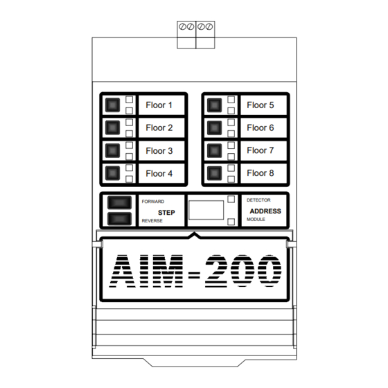
AIM-200
The Addressable Intelligent Module
for the System 5000 Fire Alarm Control Panel
Floor 1
Floor 2
Floor 3
Floor 4
FORWARD
STEP
REVERSE
12 Clintonville Road
Northford, CT 06472
Phone: 203-484-7161
Fax: 203-484-7118
Floor 5
Floor 6
Floor 7
Floor 8
DETECTOR
ADDRESS
MODULE
Document# 15949
E E E E E
10/29/97 Revision:
P/N 15949:E1
ECN 97-407
Advertisement
Table of Contents

Related Manuals for Notifier AIM-200

Summary of Contents for Notifier AIM-200
- Page 1 12 Clintonville Road Northford, CT 06472 Phone: 203-484-7161 Fax: 203-484-7118 AIM-200 The Addressable Intelligent Module for the System 5000 Fire Alarm Control Panel Floor 1 Floor 5 Floor 2 Floor 6 Floor 3 Floor 7 Floor 4 Floor 8 DETECTOR...
- Page 2 Document 15949 Rev. E 4/12/95 P/N 15949:E Technical Manuals Online! - http://www.tech-man.com...
-
Page 3: Table Of Contents
3.7: The CMX-2 ............28 3.8: The Addressable Manual Pull Station ..... 32 3.9: The Intelligent Detector ........33 3.10: Inserting the AIM-200 Cards ......34 Section Four: Programming ............35 4.1: Default Zone Map ..........35 4.2: Display Status ..........38 4.3: Program Edit ............ -
Page 4: Section One: The Aim-200
DHX-501/DHX-502 Intelligent Duct Detector Housing (for use with SDX-551 only) The 198 devices are mapped into eight software zones by the AIM-200. The status of these zones is reported to the CPU-5000. The AIM-200 includes a digital display for identifying the exact device address within a zone. -
Page 5: Section Two: Inventory
Card File A special card file is attached to the bottom front of the AIM-200. Several standard 4 in. by 2-1/4 in. cards are provided and may be marked with device information by the installer. A reference card, which defines all display codes, is included. -
Page 6: Optional Peripherals
The sensitivity of each detector can be set by BX-501 Base the programmer at the AIM-200 for one of three levels (low, medium, and high). Each detector responds to an address that is set in the head via built-in rotary decimal switches. -
Page 7: Addressable Modules
2.2 Optional Peripherals: Addressable Modules Control and Monitor Modules The CMX-2 control module and the MMX-1 monitor module provide the interface between the System 5000 and conventional initiating and notification devices. Both types of modules respond to an address C A U T IO N that is set by the installer with built-in rotary decimal switches. - Page 8 BGX-101L FIRE The addressable manual pull station features a key-lock reset. The pull station responds to an address set by the installer with built-in rotary decimal switches. Includes key. PUSH IN THEN PULL DOW N System Sensor (SSD) A2143-00 The 47K end-of-line resistor assembly is used in the supervision of MMX-1 Monitor and CMX-2 Control Module circuits.
-
Page 9: Section Three: Installation
Mount the AIM-200 to a CHS-4 Chassis. Insert the tab on the bottom of the AIM-200 into the slot on the bottom of the CHS-4. Fasten the AIM-200 to the top of the CHS-4 using the two captive screws in the top corners of the module. - Page 10 From CPU-5000 CPU-2000 To Next Module AIM-200 aim200-3 Figure 3-2: Connecting the Ribbon Cable CAUTION: Do not connect any other device or circuit to the alarm relay contacts on the CPU-5000 while the alarm bus cable (Part No. 71033) is installed in the system.
-
Page 11: Wiring The Communications Circuit
(Figure 3-19). Loop Capacity The capacity of each AIM-200 includes up to 99 intelligent detectors and an additional combination of up to 99 addressable pull stations, control modules, and monitor modules. One to ten AIM-200s can be employed, depending on system requirements. - Page 12 Table 3-1: Communications Loop Performance Fault Condition Single Single Loop has Loop Loop Loop Commun Open on Ground Been Shorted Shorted Opened Loss Loop on Loop Shorted with Opened Grounded Grounded Control Panel Non-Redundant (2-Wire) Loop Operation Trouble Trouble Trouble Trouble Trouble Trouble...
- Page 13 Figure 3-4: AIM-200 Wiring Requirements Non-Redundant Circuit Branch B Branch C Branch E For Each Loop: Branch D Add the lengths of all the branches on one loop. This sum cannot exceed 10,000 feet per loop. (Branch A) + (Branch B)
- Page 14 No T-tapping is allowed on a redundant circuit. Loop Loop Return + - + - aimwire2 A IM -2 0 0 Figure 3-5: Redundant Circuit Total length of the communications loop pair cannot exceed 10,000 feet (measured from the control panel out, and back to the control panel). The DC resistance of the communications loop pair cannot exceed 40 ohms.
- Page 15 Figure 3-6: Non-Redundant Communications Loop Document 15949 Rev. E 4/12/95 P/N 15949:E Technical Manuals Online! - http://www.tech-man.com...
- Page 16 Figure 3-7: Redundant Communications Loop Document 15949 Rev. E 4/12/95 P/N 15949:E Technical Manuals Online! - http://www.tech-man.com...
- Page 17 Premises Premises Area "1" Area "3" ISO-X ISO-X M500XJ M500XJ Isolator Module Isolator Module Loop Loop Return + - + - AIM-200 commloop3 Figure 3-8: Isolated-Redundant Communications Loop Document 15949 Rev. E 4/12/95 P/N 15949:E Technical Manuals Online! - http://www.tech-man.com...
- Page 18 Shield Termination in No Conduit Do not allow the shield drain wire to enter the control panel cabinet. Connect the drain wire to the outside of the cabinet via a BX-type connector. Shield ( + ) ( - ) System 5000 FC-2000 Cabinet Shield...
- Page 19 Shield Must employ metal conduit and a metal box. AIM-200 Shield2 FC-2000 Controller Enclosure System 5000 Cabinet Figure 3-11: Shield Termination in Partial Conduit Do not allow the shield drain wire to enter the control panel cabinet or the conduit. Connect the drain wire to the termination point of the conduit run (such as a single-gang box as illustrated above).
-
Page 20: The Isolator Module
3.3 The Isolator Module The loop isolator module (ISO-X) is used to protect critical elements of the communications loop from faults on other branches or sections of the loop. The ISO-X continuously monitors the circuit connected to Terminals 3 (-) and 4 (+). Upon power up, an integral relay is latched on. -
Page 21: The Mmx-1
3.4 The MMX-1 Monitor Module The MMX-1 monitor module is an addressable module that monitors normally open con- tacts, shorting type alarm initiating devices. The supervised MMX-1 circuit can be wired as an NFPA Style B or Style D initiating device circuit. There is no limit to the number of contact type devices installed on a monitor module circuit. -
Page 22: The Mmx-2
3.5 The MMX-2 Monitor Module The MMX-2 monitor module is an addressable module that monitors conventional two-wire smoke detectors. The supervised MMX-2 circuit can be wired as an NFPA Style B or Style D initiating device circuit. Refer to the Device Compatibility Document for the type and number of detectors the MMX-2 will support. -
Page 23: The Mmx-101
3.6 The MMX-101 Monitor Module Set the module address with these switches. ADDRESS LOOP mmx101 IDC (-) IDC (+) SLC (+) SLC (-) (White) (Violet) (Red) (Black) The MMX-101 monitor module is an addressable module that is functionally and electrically identical to an MMX-1 monitor module (Style B circuits only), but offered in a smaller pack- age for mounting directly in the electrical box of the contact-type device being monitored. - Page 24 Figure 3-13A: NFPA Style B Initiating Device Circuit Document 15949 Rev. E 4/12/95 P/N 15949:E Technical Manuals Online! - http://www.tech-man.com...
- Page 25 24 VDC filtered, regulated, ressettable power MPS-24A, TB3 Terminals 2 (-) and 1 (+) AIM-200 MPS-24B, TB2 Terminals 2 (-) and 1 (+) UL-listed 24VDC power limited, resettable, power supply for Fire Protective Signaling Figure 3-13B: NFPA Style B Initiating Device Circuit Document 15949 Rev.
- Page 26 Figure 3-14A: NFPA Style D Initiating Device Circuit Document 15949 Rev. E 4/12/95 P/N 15949:E Technical Manuals Online! - http://www.tech-man.com...
- Page 27 24 VDC filtered, regulated, resettable power MPS-24A, TB3 Terminals 2 (-) and 1 (+) AIM-200 MPS-24B, TB2 Terminals 2 (-) and 1 (+) UL-listed 24VDC power limited, resettable, power supply for Fire Protective Signaling Figure 3-14B: NFPA Style D Initiating Device Circuit Document 15949 Rev.
-
Page 28: The Cmx-2
3.7 The Control Module The CMX-2 control module is an addressable module that supervises and switches power to a notification appliance circuit. The CMX-2 circuit can be wired as an NFPA Style Y or Style Z notification appliance circuit. Alternately, the CMX-2 can be employed as a Form-C control relay. - Page 29 Figure 3-15: CMX-2 Control Module (Form-C Relay) Break Tabs To configure a CMX-2 as a Form-C relay, the two tabs must be broken off of the module. Use a pair of needle-nose pliers to break off each tab. Communications Loop Connections Connect the communications loop to CMX-2 Terminals 1(-) and 2 (+).
- Page 30 Alarm polarity shown Figure 3-16: NFPA Style Y Notification Appliance Circuit Document 15949 Rev. E 4/12/95 P/N 15949:E Technical Manuals Online! - http://www.tech-man.com...
- Page 31 Alarm polarity shown Figure 3-17: NFPA Style Z Notification Appliance Circuit Document 15949 Rev. E 4/12/95 P/N 15949:E Technical Manuals Online! - http://www.tech-man.com...
-
Page 32: The Addressable Manual Pull Station
3.8 The Addressable Manual Pull Station BGX-101L Installation The BGX-101L is an addressable manual pull station with a key-lock reset feature. Connect the communications loop to BGX-101L red wire (+) and black wire (-). If additional devices are to be connected to the SLC loop after the BGX-101L, wire-nut the continuance of the loop to the red and black wires. -
Page 33: The Intelligent Detector
3.9 The Intelligent Detector The BX-501and B501 bases provide the connection between the AIM-200 communications loop and SDX-551 (751), CPX-551 (751), and FDX-551 intelligent detectors. Installation Connect the communications loop to Terminal 1(-) and Terminal 2(+) on the BX-501. If employing an RA400Z remote LED annunciator, connect the RA400Z positive ter- minal to BX-501 Terminal 3 and the negative Terminal to BX-501 terminal 1. -
Page 34: Inserting The Aim-200 Cards
3.10 Inserting the AIM-200 Cards Seven AIM-200 cards are provided in a plastic pouch. Remove and discard the cover card. After the appropriate point informa- tion has been entered onto the cards, they may be inserted into Rolodex Cards for AIM-200 the module as shown below. -
Page 35: Section Four: Programming
Programming the AIM-200 involves two modes of operation: Auto-Program, (password 231-1332) and Program Edit (password 231-3112). A third function, Display Status, allows the programmer to review the entire AIM-200 program. Program Clear (password 231-5678), allows the clearing of an existing program from non-volatile memory. -
Page 36: Forward
A zone that the device has been mapped to is indicated by the red zone alarm LED. Devices may be mapped to any one or all of the eight AIM-200 zones. The AIM-200 will require that each MMX Monitor Module or intelli- gent detector be mapped to at least one zone (one zone must be selected at any point in time). - Page 37 Programming Switches Accepting or Rejecting Devices The ENTER and SKIP LEDs will flash while the AIM-200 is in Auto-Program or Program Edit mode. Auto-Program To accept a new device, press the ENTER switch. To reject a device, press the SKIP switch.
- Page 38 Entering Auto-Program Mode Once in Auto-Program mode, the AIM-200 turns off all LEDs, places a flashing “AP” on the digital display, and begins polling all 198 possible addresses. It stores the address and type of each device as found.
- Page 39 Acknowledge the System The CPU-5000 piezo sounder will Trouble (if desired). silence. Enter the Auto-Program The LEDs illuminated on the AIM-200 password: 231-1332. will flash at the slower rate. Push ENTER. All LEDs will be turned off will be flashing for “Auto-Program.”...
-
Page 40: Program Edit
The Program Edit function allows the programmer to change an existing program in the AIM-200 memory. If Program Edit mode is entered directly from Auto-Program mode, the programmer will enter the Program Edit mode at Step 5 of the following instructions. -
Page 41: Alarm Bus
4.4 Program LED Latch Early version Notifier analog detectors and modules have the capability to turn on up to six LEDs on a single signaling line circuit. Notifier "R4" devices (Release 4-1-91) have the capability to turn on up to 99 detector LEDs plus five module LEDs. -
Page 42: General Alarm Service
At this point, you must execute Auto-Program so that the AIM-200 can determine which devices are installed on the loop. At least one device must be installed on the AIM-200 loop. If the programming key is re- moved after Program Clear and before Auto-Program is executed, the AIM-200 will register a trouble condition by illuminating the yellow trouble LEDs on Zones 1, 3, 5, and 7. -
Page 43: Backup Alarm Bus
4.6 Default Zone Map Upon initial power up, and after clearing AIM-200 memory (Program Clear), intelligent de- tectors and addressable modules installed on an AIM-200 loop are automatically mapped to default zones. Any changes to this map must be made through Program Edit. This default map is illustrated in Figure 4-1. -
Page 44: Display Status
Key and pressing the DISPLAY STATUS switch. No password is required. Note: The AIM-200 will cease monitoring its devices while in this mode and the CPU-5000 will report System Trouble. Alternately, this mode may be entered without key or password by pressing and holding the DISPLAY STATUS switch in for two seconds. -
Page 45: Forward
By pressing any one of Zone Switches 1 through 8, the operator can advance directly to a desired range of addresses. The AIM-200 will jump to the lowest address of a programmed device within that range. The STEP-FORWARD and STEP-REVERSE switches can be used to move to devices within each range. -
Page 46: Section Five: Operation
The AIM-200 zone assumes the status of any device mapped to that zone that enters an alarm or trouble condition. If any of the initiating devices are in alarm, the zone is reported in alarm. -
Page 47: Forward
Step Switches - Two switches, STEP FORWARD and STEP REVERSE, are provided for advancing the display. If multiple alarms or troubles exist in the AIM-200, and the display is automatically advancing through them, pressing either of these two switches will stop the automatic advance and allow the operator to control the advancement through the display. - Page 48 NFPA Style 6 field wiring may be used to ensure full operation in the event of a single break in the loop wiring. When set for Style 6, the AIM-200 latches a wire failure and then must be manually reset to re-test and clear the fault. When the loop fault is latched on, the AIM-200 turns on the yellow LOOP FAULT LED and reports trouble for all zones that are not in alarm.
- Page 49 Table 5-1: AIM-200 Event Codes Device Type Status Photo Detector Normal, med. sensitivity Photo Detector Normal, low sensitivity Photo Detector Normal, high sensitivity Photo Detector Alarm Photo Detector Trouble Photo Detector No answer Photo Detector Disabled Photo Detector Unsatisfactory (failed automatic self-test) Ion Detector Normal, med.
-
Page 50: Appendix A: Operating The Control Modules
Appendix A: Operating Control Modules Optional CMX-2 control modules can be installed on the AIM-200 addressable loop. When using one or more CMX-2s, four types of control options are available: General Alarm, Control-by-Zone, Control-by-Module, and Control-by-Detector. The CMX-2 zone mapping and address assignments required for each control option are described below. -
Page 51: Document
4) Activate (alarm) each initiating device on the AIM-200. 5) Return to the panel and verify that the AIM-200 2 digit display is stepping through all devices that were alarmed. 6) Reset the system and enable all eight AIM-200 zones. - Page 52 Alarm Bus - The alarm bus is implemented with a two wire daisy chain that connects to each AIM-200. It is used to provide a manual evacuation control of CMX-2 modules and to manually silence these modules; for general alarm control functions, and to provide a backup connection between multiple AIM-200s so that the panel may still function in general alarm even if the CPU fails.
- Page 53 Signal Silence has no effect on CMX-2 Control Modules that are Form-C Type , ad- dress 60 or higher, or that are mapped to any AIM-200 zone. These modules can only be silenced by the RESET switch on the CPU. Document 15949 Rev.
-
Page 54: Appendix B: Aim-200 Power Requirements
Regulated Power Required in Alarm Use Table B-2 to determine the amount of current drawn by the AIM-200(s) in the System 5000 during an alarm. Place the Total Alarm Current obtained in the Installing the System 5000 Technical Bulletin in this manual when calculating regulated requirements in the alarm state for the control panel. -
Page 55: Appendix C: Aim-200 Point Annunciation
LCD-80 Liquid Crystal Display on the RS-485 interface. The System 5000 annunciates the AIM-200 installed directly to the right of the CPU. Note that an annun- ciator cannot be used to execute manual ON/OFF control of intelligent AIM-200 points, only standard System 5000 zones. - Page 56 Table C-1: Comparison Report - AIM-200 vs. LCD-80 Annunciator Address AIM-200 Points LCD-80 Points "01" 1-64 system points 1-64 "02" 1-64 AIM detectors 65-128 "03" 1-64 AIM modules 129-192 "04" 65-96 AIM detectors 193-224 65-96 AIM modules 225-256 Document 15949 Rev.
-
Page 57: Document 15949 Rev. E 4/12/95 P/N 15949:E
NOTES Document 15949 Rev. E 4/12/95 P/N 15949:E Technical Manuals Online! - http://www.tech-man.com... - Page 58 NOTES Document 15949 Rev. E 4/12/95 P/N 15949:E Technical Manuals Online! - http://www.tech-man.com...
- Page 59 Document 15949 Rev. E 4/12/95 P/N 15949:E Technical Manuals Online! - http://www.tech-man.com...
- Page 60 BACK COVER Document 15949 Rev. E 4/12/95 P/N 15949:E Technical Manuals Online! - http://www.tech-man.com...
Need help?
Do you have a question about the AIM-200 and is the answer not in the manual?
Questions and answers