Table of Contents
Advertisement
Advertisement
Table of Contents

Summary of Contents for ScanTools ECUsim 5100
- Page 1 User Guide ™ ECUsim 5100 Professional Multiprotocol 3-PIM OBD-II ECU Simulator...
- Page 2 Information contained in this document is subject to change without notice. Trademarks are property of their respective owners. © 2010 ScanTool.net LLC. All rights reserved. Printed in the United States of America. ECUsim™ 5100 User Guide...
-
Page 3: Table Of Contents
Table of Contents Overview ........................4 General Features......................5 Package Contents......................5 User Interface......................6 Front Panel ........................6 Back Panel........................7 Basic Operation.......................8 Setup..........................8 Using the Simulator..................... 8 UART Communication ..................9 Installing USB Drivers....................9 Terminal Setup ......................9 PIM Configuration ....................10 Supported Commands.....................10 Advanced Operation .................. -
Page 4: Overview
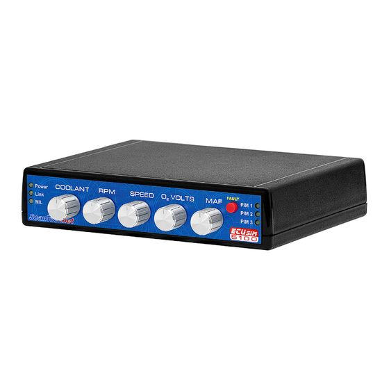
1.0 Overview ECUsim 5100 is a small, lightweight, benchtop simulator that can be used for testing and development of OBD devices and software. It supports all legislated OBD protocols, fixed and user adjustable parameter IDs (PIDs), diagnostic trouble codes (DTCs), freeze frames, and many other SAE J1979 services. -
Page 5: General Features
• Standard J1962F connector • Firmware upgradeable 1.2 Package Contents • ECUsim 5100 unit (with 1, 2, or 3 installed PIMs) • 110/220 VAC to 12 VDC switching power supply • US style power cable • OBD connector dust cover •... -
Page 6: User Interface
2.0 User Interface ECUsim 5100 can be used as a stand alone simulator, or in conjunction with a PC. It features a number of interface elements on both the front and back of the unit. 2.1 Front Panel Power LED... -
Page 7: Back Panel
2.2 Back Panel PIM Select switch USB connector Diagnostic Link Connector (DLC) Configuration DIP switch PIM ALL. Down position: makes all three PIMs active at the same time. Up position: PIM selection is controlled by the PIM Select switch b. 5BAUD/FAST. Selects the type of initialization for ISO 14230-4. Down: 5 baud init, up: fast init. -
Page 8: Basic Operation
3.0 Basic Operation ECUsim is configured at the factory according to your specifications (number of PIMs, assigned protocols) and is ready to be used out of the box. For custom configuration, see Section 5.0, PIM Configuration. 3.1 Setup To set up the simulator, follow these steps: Use the Configuration DIP switch to set the desired options. -
Page 9: Uart Communication
4.0 UART Communication ECUsim 5100 features a USB connection. On a Windows or Linux PC, the drivers create virtual COM ports which allow communication using any suitable serial port terminal (e.g., HyperTerminal). Set PIM ALL switch to OFF In order to communicate with a PIM, the PIM ALL switch must be in the “up”... -
Page 10: Pim Configuration
5.0 PIM Configuration On startup or reset, the PIM prints the configuration summary that looks similar to this: STSP300 v2.1.0 (C) 2010 ScanTool.net, LLC OBD Protocol J1850 PWM ECU0 Address 10 ECU1 Address 18 ECU2 Address 28 Press the Enter key to display the command prompt: > The PIM is now ready to accept user commands. 5.1 Supported Commands The following is a summary of currently supported commands: MON 0/1... -
Page 11: Advanced Operation
SP x Switch protocol to ‘x’, where ‘x’ is the protocol number. Protocol Protocol Number none J1850 PWM J1850 VPW ISO 9141-2 ISO 14230-4 ISO 15765-4 The 5BAUD/FAST switch determines the type of initialization (5 baud or fast). Baud rate and CAN ID type are controlled by the 250K/500K and 11/29 BIT switches. ... -
Page 12: Iso 14230-4 (Fast Init)
6.2 ISO 14230-4 (Fast Init) After switching to the ISO 14230-4 protocol with fast init option, the PIM will print the following status message: <WAITING FOR FAST INIT> It will not respond to any requests until the bus is initialized. After a successful initialization sequence, the PIM will print: <FAST INIT: OK> ... -
Page 13: Status Messages
Tx: 7E9 41 00 88 18 00 10 Tx: 7EA 41 00 00 08 00 10 Same exchange on 29-bit CAN: Rx: 18DB33F1 01 00 Tx: 18DAF110 41 00 BE 1B 30 13 Tx: 18DAF118 41 00 88 18 00 10 Tx: 18DAF128 41 00 00 08 00 10 Monitoring can be turned off using the MON 0 command to increase the refresh rate. To enable monitoring again, issue MON 1. 6.5 Status Messages <UART TX OVERFLOW> UART transmit buffer overflow detected. -
Page 14: Virtual Ecus
7.0 Virtual ECUs There are three virtual ECUs: Engine Control Module (ECM), Transmission Control Module (TCM), and Anti-lock Braking System module (ABS). The ECUs support both physical and functional addressing, as specified in the SAE J2178, Part 1 and ISO 15765-4 documents. Functional address supported by the ECUs depend on the selected protocol and, in the case of ISO 15765-4, the ID type (11-bit or 29-bit): Protocol(s) -
Page 15: Engine Control Module (Ecm)
7.1 Engine Control Module (ECM) The following summarizes modes, PIDs, and Infotypes supported by the PCM. 7.1.1 ECM: Mode 1 Description Fixed/Variable Hex Value Scan Tool Display Supported PIDs fixed BE1B3013 01-1F Monitors/DTC fixed 0007EF80 See PID 01 Count/MIL Monitors table Fuel System fixed 0201... - Page 16 Supported PIDs fixed 80022001 21-3F Distance Traveled fixed 03E8 1000 km While MIL is Activated Fuel Level Input fixed 50.2% Barometric fixed 100 kPa Pressure Supported PIDs fixed 44000000 41-5F Control Module fixed 2EE0 12 V Voltage Ambient Air fixed 20°C Temperature 7.1.1.1 PID 01 Monitors...
-
Page 17: Ecm: Mode 2
7.1.2 ECM: Mode 2 When the user generates a malfunction event, the following freeze frame is stored: Description Hex Value Scan Tool Display Supported PIDs 01-1F 48180000 DTC that Caused F.F. Storage 0100 P0100 Engine Coolant Temperature 100°C Engine RPM 4E20 5000 rpm Vehicle Speed Sensor... -
Page 18: Ecm: Mode 7
7.1.5 ECM: Mode 7 When the MIL is on, Mode 7 reports four pending DTCs: P0107 P0207 P0307 C0307 7.1.6 ECM: Mode 9 The following infotypes are supported: Infotype Description Scan Tool Display Supported Infotypes VIN Message Count 1G1JC5444R7252367 Calibration ID message count Calibration ID JMB*36761500 CVN Message Count... -
Page 19: Transmission Control Module (Tcm)
7.2 Transmission Control Module (TCM) The following summarizes modes, PIDs, and Infotypes supported by the TCM. 7.2.1 TCM: Mode 1 Description Fixed/Variable Hex Value Scan Tool Display Supported PIDs fixed 88180010 01-1F Monitors/DTC fixed 00000000 All monitors not Count/MIL supported Engine Coolant variable, knob #1 00 to FF... -
Page 20: Tcm: Mode 7
7.2.4 TCM: Mode 7 When MIL is on, Mode 7 reports two DTCs: P0102 U1600 7.3 ABS Control Module (ABS) The following summarizes modes, PIDs, and Infotypes supported by the ABS. 7.3.1 ABS: Mode 1 Description Fixed/Variable Hex Value Scan Tool Display Supported fixed... -
Page 21: Firmware Updates
8.0 Firmware Updates Each PIM features a bootloader, which allows the user to update the device’s firmware in the field through the USB port. Updates are posted on the ECUsim internet product page as they become available. Once you download the update, follow the steps to update the PIM: Extract the contents of the ZIP file to a folder on your computer. -
Page 22: Appendix A: Specifications
Appendix A: Specifications Dimensions 7.2 x 5.5 x 1.5 in (183 x 140 x 38 mm) Weight 14 oz (400 g) Power 12 VDC @ 2A (max) OBD Protocols SAE J1850 PWM SAE J1850 VPW ISO 9141-2 ISO 14230-4 (KWP2000) ISO 15765-4 (CAN 250/500 kbps, 11/29 bit) USB Type B PC Port...
Need help?
Do you have a question about the ECUsim 5100 and is the answer not in the manual?
Questions and answers