Table of Contents
Advertisement
Quick Links
Advertisement
Table of Contents

Summary of Contents for CHP Extra 300S
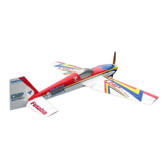
- Page 1 Chip Hyde Products 34% Competition Series Extra 300S ARF ASSEMBLY MANUAL...
- Page 2 Copyright 2005 - Chip Hyde Products Distributed by: Chip Hyde Products Phone: ( 520)-458-1414 Visit the Web: www.chiphyde.com & E-mail: hydecompprod@theriver.com Aeroworks Phone: (303) 366-4205 Fax: (303) 366-4203 Visit the Web: www.aero-works.net E-mail: Info@aero-works.net Warning An R/C aircraft is not a toy! If misused, it can cause serious bodily harm and damage to property. Fly only in open areas, preferably AMA (Academy of Model Aeronautics) approved flying sites, following all instructions included with your radio and engine.
-
Page 3: Contents Of Manual
Contents of Manual Cover page Introduction -Intended Use -Warranty Kit Contents -Parts -Hardware Bags Building Instructions -Beginning Construction -Wing Assembly -Elevator Servo Installation -Stab and Elevator Assembly -Rudder Servo Installation -Cowl Mounting -Motor Standoffs -Motor Installation -Cowl Air Lets Inlets -Landing Gear and Skirt Installation -Wheel Pant Installation -Wing Attachment... -
Page 4: Intended Use
Introduction Before starting the assembly process of your new 34% Extra 300S ARF, Please read through the assembly manual carefully, and inspect all parts and hardware for imperfections or damage. The competition series Extra 300S is a highly aerobatic airplane designed and sold by world-renowned aerobatic RC pilot Chip Hyde who is a multiple USA National, World and TOC champion. -
Page 5: Kit Contents
Kit Contents Parts: Canopy - unpainted 1 x Front Hatch cover 2 x Wings 1 x Rear Hatch cover 2 x Ailerons 1 x Rear Hatch cover bottom plate 2 x Stabs 1 x 1.5” Aluminum wing-tube 2 x Elevators 1 x .5”... - Page 6 Hardware bags included: Wheel bag 24 x Wood screws 2 x wheels Canopy screw bag 2 x axles with nuts 12 x small wood screws 4 x wheel collars with set screws Landing gear bolt bag 1 x anodized titanium tail wheel 5 x machine screws 4 x wood screws 5 x split washers...
- Page 7 Items needed to complete the Extra 100 cc Motor and Propeller 4" spinner 1 x 32 oz Fuel Tank (Gas) Push rods Ailerons - 4 x 2.5” pushrods Elevators - 2 x 2.5” pushrods Throttle - Rudder - 1 x Heavy Duty Pull-pull 4-40 cable wires kit Dubro # 4 x aileron servos (100 Inch oz min) 2 x rudder servos (130 Inch oz min) 2 x elevator servos (150 Inch oz min)
-
Page 8: Tightening And Re-Shrinking The Covering
Beginning Construction of the Competition Series Extra 300S TIGHTENING AND RE-SHRINKING THE COVERING Open your kit slowly and take care not to damage any parts of the kit. Remove all parts from their plastic protective covers for inspection. Before doing any assembly or... -
Page 9: Wing Assembly
WING ASSEMBLY 1) Locate the pre cut hinge slots in the wing and aileron. The model comes with CA style hinges pre installed, but not glued into the control surfaces. We have used the provided CA hinges with no problems. Hinge ailerons by first pushing a T pin through the center of all CA hinges. - Page 10 4) Next, place 4-6 drops of thin CA on each side of all hinges. We also recommend using a clear covering to seal all control surfaces. 5) Locate servo locations on bottom side of wings. Note: the pre cut slots in the Extra are for the new Futaba 9152 servos.
- Page 11 7) Attach servo extension leads to your servos, it will be necessary to use a “Y” harness and an 18” extension in order to connect the two servos together and have enough wire to exit the root of the wing. It is important to secure the servo connectors with tape, wire or after market clip to be certain the leads do not disconnected.
- Page 12 10) Now cut out the covering in a triangle shape from your control horn screw holes. Put a drop of thin CA in each of the three holes to harden them. Next, rough up the bottom of the control horn with some sand paper so that glue will stick to it better.
-
Page 13: Elevator Servo Installation
ELEVATOR SERVO INSTALLATION Note: As in the servo slots in the wings, the servo slots for the elevator servos are cut for the new Futaba 9152 servos. Again, these servos a slightly bigger than standard size servos, and therefore, we have provided standard size servo trays to accommodate a standard servo. - Page 14 2) Slide the servo and tray as far toward the bottom of the slot as possible. Remove elevator from stab. Insert stab tube and anti rotation dowel into one stab and test fit the stab by sliding it onto the airplane (on the same side as your servo and tray).
- Page 15 5) Use an Xacto knife to remove the covering 1/16” to the inside of the line. This is going to allow a good bond when gluing the tray to the fuse. 6) Note: Before you glue the tray to the fuse, you may want to cover the top and sides of the tray with white ultra cote or paint it.
- Page 16 STANDARD SERVO METHOD #2 The second method mounts the standard size servo plate to the inside of the fuse. This requires using a Dremel tool to enlarge the pre-existing servo slot in the fuse. 1) Test fit the servo in the fuse. Center the servo in the slot both front to back and up and down.
- Page 17 3) Test fit the servo into the new slot to make sure the servo fits all the way inside the hole you have made. 4) Slide the standard sized servo tray into the fuse and hold up in place from behind (use the other elevator servo slot hole to get your fingers into the fuse and hold in place).
- Page 18 6) Repeat steps 1-5 to other side before securing the servo in slot to allow you to hold the tray in position again. Once both plates are installed securely, attach servos to fuse with servo screws making sure the servo output shaft is toward the tail of the airplane.
- Page 19 3) Next we will mount the control horn. On the bottom of one of the elevators, measure ¾” from the root end. This mark is the centerline of the control horn. 4) Next, Line the control horn up with the leading edge of the elevator and center the control horn over the line you just made.
- Page 20 Slide stab tube and stab anti rotation dowel though fuse. Use ruler to center both tube and dowel in the fuse 7) Slide one stab on to stab tube and dowel. Measure to make sure tubes have not moved. Collect the 4 bolts from the screw bag.
-
Page 21: Rudder Servo Installation
RUDDER SERVO INSTALLATION Note: If you are using the new Futaba 9152 servos, you may use the provided servo tray doubler plate to stiffen the rudder servo floor. Glue to either the top or the bottom (builder’s choice) of the radio floor and follow the proceeding steps. If you are using a standard sized servo, use the provided standard sized servo tray and follow the proceeding steps. -
Page 22: Cowl Mounting
3) Drop servos back into servo slots and mount to fuse with servo screws. Install rudder pull-pull cables as per manufacturer instructions. 4) For your convenience, the pull-pull cable exits have been pre-cut in the rear of the fuselage. The control horn location is ¾”... - Page 23 2) On the piece of tape on the fuse sides, mark the centerline of each of the six cowl attachment mounts. This will help to align the holes to drill to attach the cowl. 3) Slide cowl over fuse to the edge of the tapeline.
- Page 24 5) Collect the six machine bolts and six blind nuts for the cowl from the cowl mount bag. Drill all six cowl mount tabs out with a 13/64” drill bit to accommodate the blind nuts. Install blind nut to cowl attachment tabs and use CA to hold blind nuts in place.
- Page 25 INSTALLING THE MOTOR AND IGNITION The engine thrust line is 2 7/16” down from the top of the firewall. The motor is also offset ¼” to the right of center when looking at the front of the airplane. 1) Draw the engine thrust lines on the firewall.
- Page 26 3) Remove engine and drill ¼” holes to accommodate a ¼ x 20 bolt. Install the motor with pre determined stand off lengths. Make sure to use locktite on threads. 4) Install ignition per manufacturer recommendations. This is an example of a typical ignition installation: Install the ignition on the side of the engine box.
- Page 27 COWL AIR VENTS 1) Gather cowl and two air vents. Rough up the backside of the air vents and the indented air let location on the cowl with some sand paper. 2) Glue air vents to cowl with epoxy. Be sure to glue air vents so that the fins point, or open, to the back.
- Page 28 LANDING GEAR AND SKIRT INSTALLATION 1) Locate landing gear bolt bag, wheel bag, skirt bag, and landing gear. Use the 5 supplied bolts and split washers to bolt the gear to the fuse. Be sure to use locktite on the threads. 2) Use masking tape to hold the two halves of each of the skirts together.
- Page 29 4) Slide skirt back onto fuse and use 8 small wood screws provided in the skirt bag to attach skirt to fuse. Repeat above steps for other skirt. 5) Locate the main wheels, axles, and wheel collars. Attach the axle to the landing gear.
- Page 30 WHEEL PANT INSTALLAION 1) Collect wheel pants and wheel pant support blocks. Remove any paint on the inside of the wheel pant with sandpaper. Clean surface and use thick CA to glue the support block to the inside of the wheel pant. Use clamps to hold block in place while glue dries.
-
Page 31: Wing Attachment
4) Use ½” 4-40 screws and blind nuts to attach wheel pant. Repeat steps for other wheel pant (Make sure to make a left and right wheel pant!). Use locktite on screw threads. WING ATTACHMENT 1) Locate wings, wing tube, and wing attachment bolt bag. - Page 32 3) Using epoxy, glue the blocks to the inside of the fuse. Make sure not to get any glue into the hole or onto the anti- rotation pin. Note: You may want to put a thin layer of Vaseline on the anti rotation pin to prevent the epoxy from stick to it when it cures.
-
Page 33: Throttle Servo
3) Once the canopy is tacked in place, use epoxy on the inside of the canopy to permanently glue canopy to hatch. THROTTLE SERVO Note: Throttle servo location is uncut due to the different motor carburetor locations and builder's preference. The method shown is an easy and solid way to mount the throttle servo that provides very clean and accurate throttle response. - Page 34 2) Use line as a reference to establish throttle servo location. 3) Cut a hole for the throttle servo in the bottom of the engine box and attach servo with servo screws. Make a pushrod to connect the throttle servo to the throttle arm.
- Page 35 FIBER GLASS BELLY PAN INSTALLATION The belly pan for this airplane was designed to allow canister muffler to sit partially in the fuse while still being in the open air for cooling purposes. The belly pan is required no matter what type of mufflers you are using.
-
Page 36: Canister Muffler Installation
CANISTER MUFFLER INSTALLATION This airplane was designed to fit canister mufflers in the belly pan of the airplane. If you are using standard mufflers, you will need to use a Dremel tool with a drum sander to cut slots in the cowl to provide clearance for the exhaust stacks. - Page 37 3) Next, cut two ¾” by 2” strips of ¼” Liteply to attach the canisters to. These strips will be attached perpendicular to the lite-ply support bracket and will allow you to strap the canisters to the fuse to prevent movement. Glue the supports to the support bracket.
-
Page 38: Fuel Tank Installation
FUEL TANK INSTALLATION 1) Locate the fuel tank floor. Test fit the floor into the fuse. Once satisfied with fit, use epoxy to glue the plate in place. Use weight to hold the plate in place while glue dries. 2) Assemble fuel tank as per manufacturer instructions. - Page 39 Balance the 300S with fuel tank empty otherwise ready to fly. FLYING We believe the Extra 300S will be one of the finest flying airplanes you will ever fly. The 300S has no bad habits and very slow speed stall characteristics.
Need help?
Do you have a question about the Extra 300S and is the answer not in the manual?
Questions and answers