Table of Contents
Advertisement
Advertisement
Table of Contents

Related Manuals for Redarc BMS1215S2


Summary of Contents for Redarc BMS1215S2
- Page 1 Battery Management System BMS1215S2...
-
Page 2: Warnings And Safety Instructions
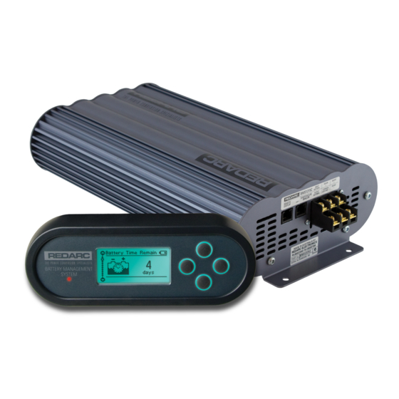
THE BMS1215S2 The Redarc BMS1215S2 Battery Management System is a complete charging solution for you Auxiliary or House battery. The system incorporates 240V AC, 12/24V DC and 12V Solar inputs to provide a 12V charging output at a maximum 15A rating. -
Page 3: Table Of Contents
CONTENTS Table of Contents Page Warnings and Safety Instructions Contents Features and Benefi ts 1 Introduction 1. General Description 2. The Remote Monitor 3. The Kit Includes 4. Specifi cations 5. Multi-stage Charging Process 2 INSTALLATION Guide 1. System Layout 2. -
Page 4: Features And Benefi Ts
It is manufactured with high-quality components to ISO9001 quality and ISO14001 environmental standards and backed with Redarc’s quality service and two-year warranty. 4. The BMS’s DC-DC charging enables optimal charging of house batteries, even if they have different chemical characteristics from the vehicle battery. -
Page 5: Introduction
INTRODUCTION General Description The BMS is designed to offer a complete solution to battery charging and maintenance needs for recreational automotive applications. The BMS incorporates AC, DC and Solar inputs to achieve the best charge to a house battery. The Remote Monitor The BMS comes with a Remote Monitor designed to give you house battery information and charge status along with critical system information while charging is in progress. -
Page 6: Specifi Cations
INTRODUCTION Specifi cations Electrical Specifi cations Inputs AC Input Input Voltage Range 220 - 240V AC, 50 - 60Hz Power Rating 280W Effi ciency Connection Mains Plug DC Input Input Voltage Range 9 - 32V Turn ON/OFF Threshold 12V (24V) 13.2V/12.7V (26.4V/25.4V) Power Rating 260W... - Page 7 INTRODUCTION Figure 1.4.1 - Main Unit Dimensions BATTERY MANAGEMENT SYSTEM Figure 1.4.2 - Remote Monitor Dimensions...
-
Page 8: Multi-Stage Charging Process
INTRODUCTION Multi-stage Charging Process The BMS incorporates two different multi-stage charging profi les – Touring (3-stage) and Storage (5-stage) – which can be selected in the Battery Mode menu on the Remote Monitor. Touring Mode Touring mode is designed for use when ‘on the road’. Touring mode offers a 3-stage charging profi... - Page 9 INTRODUCTION Storage Mode Storage mode is designed to charge the house battery to its optimal level and maintain that level while your caravan is in storage. This mode requires all loads to be switched off or disconnected from the house battery before charging. It uses a 5-stage charging profi...
- Page 10 INTRODUCTION IMPORTANT When the BMS is set to ‘Storage’ mode and no valid charging sources are connected, it will enter a ‘Sleep’ mode after 2-3 seconds. The sleep mode is designed to limit the amount of current drawn from the output battery by the system whilst in Storage mode and does this by switching the screen and all non-essential functions off.
-
Page 11: Installation Guide
INSTALLATION GUIDE System Layout Remote Solar Panels Monitor (Not Supplied) Vehicle BMS1215S2 To Loads Battery Battery Main Unit (Not Supplied) (Not Supplied) Monitor DC - DC Power Source House Battery (Not Supplied) 240VAC Mains Power Figure 2.1.1 - System Layout... -
Page 12: Mounting The Main Unit
The Main Unit must be fi xed using suitable screw mounts. Do NOT use adhesive to mount the unit because this is unreliable. Redarc recommends that the Main Unit be mounted to optimise airfl ow past the heatsink. Mounting the unit horizontally (see Figure 2.2.1.1) is acceptable. Do NOT mount the unit as shown in Figure 2.2.1.2 or Figure 2.2.1.3. -
Page 13: Mounting The Remote Monitor
INSTALLATION GUIDE 2.2.2 Mounting the Remote Monitor The Remote Monitor should be mounted inside the caravan or RV using the template provided inside the box. It is acceptable however to mount the Remote Monitor in any convenient location, as long as it is protected from harsh environments. -
Page 14: Wall Mount
INSTALLATION GUIDE Wall Mount Use the template provided to mark Attach the Back Plate to the wall the position and drill and cut the unig 4 suitably sized countersunk mounting holes into the wall. screws. Feed the Remote Monitor cable Clip the Inner Assembly into the through the hole and connect it to Back Plate. - Page 15 INSTALLATION GUIDE Removing the Remote Monitor The locking tabs on the back of the The locking tabs can be accessed Inner Assembly need to be unclipped through holes on the top of the from the Back Plate. backing plate when installed. Insert a fl...
-
Page 16: Installing The Current Shunt & Battery Sensor
INSTALLATION GUIDE 2.2.3 Installing the Current Shunt & Battery Sensor Wire the Current Shunt between the negative terminal of the house battery and the common ground connection using the outside connections as shown in fi gure 2.2.3.1. Connect the sense terminals on the Battery Management System to the Current Shunt inner terminals with a twisted pair of wires. -
Page 17: Dc Cable Size Requirements
6B&S automotive. The recommended maximum cable length between input vehicle battery and the BMS should not be longer than 10m for 6mm auto or 20m for 6B&S. Redarc recommends that the input wire be of the size outlined in Table 2.3.1. Distance (metres) Recommended Cross... - Page 18 8mm² is recommended, however this will lower effi ciency by up to 3% (the recommended maximum length is 5m). NOTE: Redarc has determined these recommended cable sizes based on 50°C maximum ambient temperature, a single cable loom and does not include any connection losses.
-
Page 19: Connections To Main Unit
INSTALLATION GUIDE Connections to Main Unit WARNING Redarc recommends that this unit be installed by a suitably qualifi ed person. WARNING The AC power connection must be connected to an earthed socket outlet. Do not use the BMS AC input if the cord is damaged. (If the supply cord is damaged, it must be replaced by a special cord or assembly available from the manufacturer or service agent). - Page 20 INSTALLATION GUIDE...
- Page 21 INSTALLATION GUIDE...
-
Page 22: Batteries
INSTALLATION GUIDE Batteries WARNING Explosive gases can be generated by the house battery during the charge process, therefore the battery should be kept in a well ventilated area. WARNING When charging a battery, make sure the settings at the Battery Setup menu on the Remote Monitor are correct for the type of battery under charge. -
Page 23: Mppt Solar Regulator
INSTALLATION GUIDE MPPT Solar Regulator Solar Input The BMS is designed for use with 12V solar panels (panels that have a maximum output voltage of up to 25V). A minimum input voltage of 14V is required to start charging from a solar source. Once charging has started, the operating voltage range of the solar input can go as low as 9V and as high as 30V;... - Page 24 INSTALLATION GUIDE IMPORTANT A partially shaded panel (or low-light conditions such as dawn or dusk) will increase the target solar panel voltage level to match the maximum power point. In this situation solar will be selected as a source however little or no current will be fl...
-
Page 25: User Guide
USER GUIDE Remote Monitor The Remote Monitor is designed to give you control of how the battery is being charged, as well as up-to-date house battery and charge information at any time during the charging process. You can check battery charge status, estimated charge time and State of Charge (SOC) per hour over a day and per day over a month. -
Page 26: Navigating The Menu
USER GUIDE Navigating the Menu The BMS monitors current in and out of the house battery, keeping track of the charge remaining. This screen displays the estimated state of charge of the house battery in percentage along with a bar graph. For the duration of the initial charge cycle for a new battery this screen will show ‘Analysing’. - Page 27 USER GUIDE This screen displays a live summary of the electrical system including source type, voltage and charging current, the size of any loads running and the state of the battery under charge. Pressing ‘Down’ from the Currents screen will display the Battery Status screen. This screen displays the status of the battery under charge, including Battery Voltage and Battery Temperature.
- Page 28 USER GUIDE The BMS can be confi gured via this setting to use either a 3-stage (Touring) or a 5-stage (Storage) charging mode to get the best charge for the situation. Pressing the ‘Enter’ key at any of these screens will give you the option of changing the charge mode.
- Page 29 USER GUIDE Via this menu, you can change settings relating to the Remote Display and its operation. Pressing ‘Enter’ at this screen allows adjustment of Contrast, Brightness, Backlight, Low Voltage Alarm, Temperature and Tones. Pressing ‘Enter’ at this menu will display the Basic Settings menu items. Pressing ‘Down’ at this screen will return to the Charge Status screen.
- Page 30 USER GUIDE This screen is also found in the Basic Settings menu and gives you the option of restoring the Factory Settings for the BMS. To restore Factory Settings press the ‘Enter’ key. A caution screen will ask ‘Are you sure?’.
- Page 31 USER GUIDE If the BMS detects a problem with the charging system that does not prevent it from charging the battery, it will alert you via a Warning screen and an alarm buzzer, and continue charging. The screen will give a brief description of the problem and allow you to select either ‘Clear’...
-
Page 32: Troubleshooting
These indicators should be used to diagnose, and if possible correct any faults that may occur. If after attempting to rectify the situation, a fault still occurs, please send the unit back to Redarc for diagnosis. When attempting to diagnose a fault, cabling should be over-rated and all components, including all input sources and house battery should be connected as close as possible to the BMS. -
Page 33: Other Problems
USER GUIDE BMS WARNING MESSAGE CAUSE ACTION AC supply over voltage The internal AC converter output Contact supplier voltage is too high AC supply under voltage The internal AC converter output Contact supplier voltage is too low DC supply over voltage The DC input voltage is too high (over Check DC input, refer to specifi... -
Page 34: Faqs
USER GUIDE Frequently Asked Questions Q I want to install my remote at a distance from the main unit, but the cable supplied is only 2 metres, what can I do? A You can buy a replacement cable from any good electronics specialist. The cable must not exceed 10m in length and must be 6 Pin/6 Core RJ12 cable. -
Page 35: Two Year Warranty
Friendly, personalised, professional service and product support In the unlikely event that a technical issue arises with a Redarc product, customers are encouraged to initially contact the Redarc Technical Support Team on (08) 8322 4848 In the unlikely event that a technical issue arises with a Redarc product, customers are encouraged to initially contact the Redarc Technical Support Team on (08) 8322 4848 or or power@redarc.com.au... - Page 36 Free technical assistance! please contact Redarc Electronics 23 Brodie Road North, Lonsdale SA (08) 8322 4848 power@redarc.com.au www.redarc.com.au Copyright © 2012 Redarc Electronics Pty Ltd. All rights reserved. WARBMS1215S2 - REV6 www.redarc.com.au...
Need help?
Do you have a question about the BMS1215S2 and is the answer not in the manual?
Questions and answers