Table of Contents
Advertisement
Advertisement
Table of Contents

Related Manuals for Jackle Plasma 70 S

Summary of Contents for Jackle Plasma 70 S
- Page 1 Plasma Cutting System Plasma 70 S...
- Page 2 Plasma 70 S These operating instructions are intended to ensure safe and efficient work with the Plasma 70 S cutting unit. Please read the instructions carefully prior to initial operation of the unit. The information contained in this manual should be made available to all operational...
-
Page 3: Declaration Of Conformity
Plasma 70 S DECLARATION OF CONFORMITY within the meaning of EC recommendation EMC 89/336/EEC, appendix I respectively of EC recommendation 73/23/EEC, appendix III B Manufacturer: Jäckle Schweiß- und Schneidtechnik GmbH Riedweg 4 D – 88339 Bad Waldsee Germany We declare, that below mentioned current source corresponds to the safety requirements of the recommendations. -
Page 4: Table Of Contents
Plasma 70 S Contents Page Some general information about plasma cutting ............1 Safety Requirements ....................2 Brief description......................4 Technical Data......................5 Control Elements ......................6 Initial operation ......................8 Preparations for cutting ....................9 Cutting ........................10 Service and Maintenance ...................11 Trouble-Shooting ....................11 Description of board....................13 Spare Parts ......................14... -
Page 5: Some General Information About Plasma Cutting
Plasma 70 S 1. Some general information about plasma cutting 1.1 Operating principle In a plasma torch, the air is heated to an extremely high temperature through an electric arc, thus forming an electroconductive plasma which allows the cutting current to flow from the electrode to the workpiece. -
Page 6: Safety Requirements
Plasma 70 S 2. Safety Requirements This cutting unit has been manufactured in accordance with the relevant international standards. However, improper use or manipulation of the machine may cause hazards. a) The unit is exclusively intended for plasma cutting processes. Service personnel must be duly informed of all safety rules. - Page 7 Plasma 70 S 2.4 Electrical hazard Plasma cutting is carried out under high-tension conditions which require utmost precau- tion. Any defective or damaged parts on the torch must be replaced immediately. When ex- changing a part, always disconnect the unit (master switch in pos. 0). Only original spare parts may be used on the torch.
-
Page 8: Brief Description
Plasma 70 S 3. Brief description The Plasma Cutting Unit 70 S has been developed using the robust thyristor-control technology. It excells in multipurpose application for manual cutting operations. Its operating priciple is characterized by the following: Infinitely variable cutting current from 25 - 70 A. -
Page 9: Technical Data
Plasma 70 S 4. Technical Data Supply voltage 3-phase 400 V, 50 / 60 Hz Max. power draw 19 kVA Fuse 20 A slow Set-point range infinitely variable 20 - 70 A Max. open-circuit voltage 250 V 60 % duty cycle... -
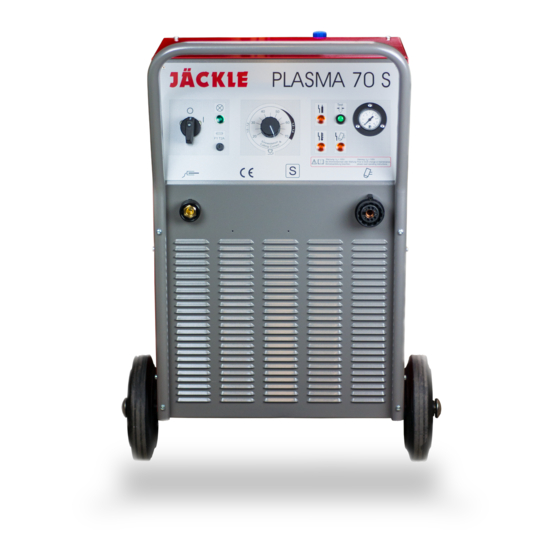
Page 10: Control Elements
Plasma 70 S 5. Control Elements Picture 5.1 Control Elements Operating Manual Page 6... - Page 11 Plasma 70 S Master switch Position "O": unit is switched off. Position "I": unit is switched on. Attention! The fan is controlled via the temperature of the current source. At the instant of starting the cutting unit in a cold state, the fan is not set to work.
-
Page 12: Initial Operation
Plasma 70 S 6. Initial operation 6.1 Installation of the cutting unit When putting the unit in place, please make sure there is sufficient space for inlet and outlet cooling air so that the rated duty cycle will be attained. -
Page 13: Preparations For Cutting
Plasma 70 S 7. Preparations for cutting 7.1 Regulation of cutting current Set the cutting current dependant to the material and thickness of the workpiece. In manual cutting operations, the current setting should be high enough to enable continu- ous manipulation of the cutting torch. -
Page 14: Cutting
Plasma 70 S 8. Cutting 8.1 Pilot arc ignition Bring the nozzle of the cutting torch to the starting point of the cut to be executed. Press torch trigger. After a short preweld gas flow time the pilot arc is ignited, and at the instant of the pilot arc impacting the workpiece, the cutting arc is formed. -
Page 15: Service And Maintenance
Plasma 70 S 9. Service and Maintenance This cutting unit should be serviced in regular intervals dependent on operating times and working place conditions. Check filter pressure reducer unit. Change cartridge, if required. Clean unit from inside by air-blasting according to degree of soiling. - Page 16 Plasma 70 S Malfunction/error Cause Remedy Pressing of torch trigger one mains phase not check mains fuse connected (mains fuse has actuates pilot contactor, been tripped, interrupted however, lead of mains cable) total failure of the pilot excessive working pressure see chapter 7.3 ‘Regulation of compressed air’...
-
Page 17: Description Of Board
Plasma 70 S 11. Description of board TPLASMA1-1 Jumper open bridges LED`s power frequency 50 Hz 60 Hz water circ. cooling o.k. mac. current 70 A 120 A air pressure o.k. temperature o.k. cutting current flows arc voltage o.k. torch trigger “on“... -
Page 18: Spare Parts
12. Spare Parts Picture 12.1 Frontview Operating Manual... -
Page 19: Picture 12.2 View From The Side
Picture 12.2 View from the side Operating Manual... - Page 20 715.019.008 case push-handle incl. assembly parts 721.024.001 bonded tired wheel 200 mm d incl. assembly parts 720.200.020 front panel ‘Plasma 70 S’ 304.024.001 master switch S225-647859 440.225.101 control knob for master switch 440.220.051 signal element 24 V, yellow 712.024.002...
- Page 21 Item Designation Stocknumber interference filter 705.024.005 control transformer 24/230/400 V, 75 VA 462.024.005 contactor DL 4K-10 / 24 V (pilot contactor) 442.024.011 600.024.002 control board Tplasma 1-1 70A/50Hz control board Tplasma 1-1 70A/50Hz (repair service) 600.024.002A control board Tplasma 1-1 70A/60Hz 600.024.005 control board Tplasma 1-1 70A/60Hz (repair service) 600.024.005A...
-
Page 22: Circuit Diagram
13. Circuit diagram Circuit diagram Plasma 70S Operating Manual...
Need help?
Do you have a question about the Plasma 70 S and is the answer not in the manual?
Questions and answers