Table of Contents
Advertisement
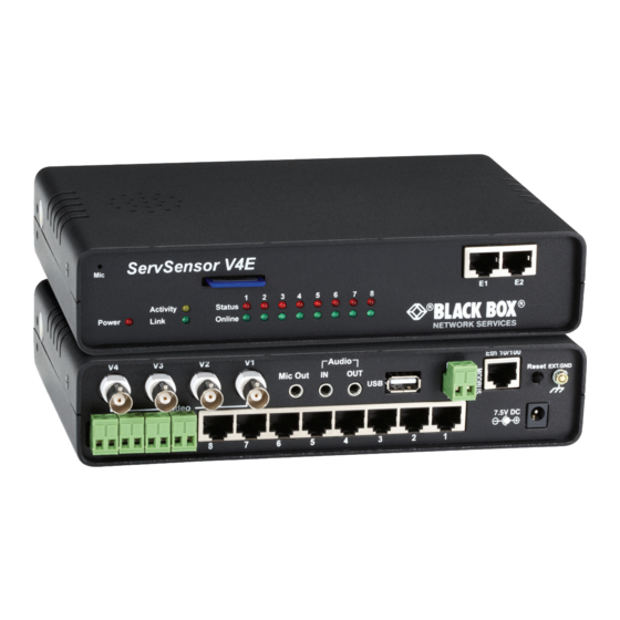
ServSensor V4E
Use this intelligent environmental monitoring
device to identify problems before they disrupt
your equipment.
Features an embedded Web server and Linux operating system.
Contact
Information
EME134A-R3
Order toll-free in the U.S. or for FREE 24/7 technical support: Call 877-877-BBOX
(outside U.S. call 724-746-5500)
www.blackbox.com • info@blackbox.com
EME134A-R3
Advertisement
Table of Contents

Subscribe to Our Youtube Channel
Related Manuals for Black Box ServSensor V4E


Summary of Contents for Black Box ServSensor V4E
- Page 1 EME134A-R3 ServSensor V4E Use this intelligent environmental monitoring device to identify problems before they disrupt your equipment. Features an embedded Web server and Linux operating system. Order toll-free in the U.S. or for FREE 24/7 technical support: Call 877-877-BBOX Contact (outside U.S.
- Page 2 Trademarks Used in this Manual Trademarks Used in this Manual Black Box and the Double Diamond logo are registered trademarks of BB Technologies, Inc. Bluetooth is a registered trademark of Bluetooth Sig, Inc. Unicenter is a registered trademark of Computer Associates Think, Inc.
- Page 3 FCC and IC RFI Statements Federal Communications Commission and Industry Canada Radio Frequency Interference Statements This equipment generates, uses, and can radiate radio-frequency energy, and if not installed and used properly, that is, in strict accordance with the manufacturer’s instructions, may cause inter ference to radio communication. It has been tested and found to comply with the limits for a Class A computing device in accordance with the specifications in Subpart B of Part 15 of FCC rules, which are designed to provide reasonable protection against such interference when the equipment is operated in a commercial environment.
- Page 4 NOM Statement Instrucciones de Seguridad (Normas Oficiales Mexicanas Electrical Safety Statement) 1. Todas las instrucciones de seguridad y operación deberán ser leídas antes de que el aparato eléctrico sea operado. 2. Las instrucciones de seguridad y operación deberán ser guardadas para referencia futura. 3.
-
Page 5: Table Of Contents
Table of Contents Table of Contents 1. Specifications ......................................6 2. Overview ......................................7 2.1 Introduction ....................................7 2.2 What‘s Included ....................................7 2.3 Hardware Description ..................................8 2.3.1 Front Panel ................................... 8 2.3.2 Back Panel .................................... 9 3. Installation ......................................10 3.1 Setting the IP Address ..................................10 3.2 Testing the New IP Address with the “Ping”... -
Page 6: Specifications
Chapter 1: Specifications 1. Specifications Certifications: AdRem NetCrunch, Quest Software–Big Brother , Castle Rock, HP OpenView , IBM Tivoli , LoriotPro, Logalot, ® ® ® ® ® MRTG , SiteScope , Somix —WebNM and Denika , WhatsUp Gold, Computer Associates Unicenter ®... -
Page 7: Overview
2.2 What’s Included Your package should contain the following items. If anything is missing or damaged, contact Black Box Technical Support at 724-746-5500. • (1) ServSensor V4E unit •... -
Page 8: Hardware Description
These lights also indicate if the unit is operating in safe mode. This is when the unit loads the operating system (OS) with a minimal set of drivers. If your device enters safe mode after rebooting, contact Black Box Technical Support at 724-746-5500 or info@blackbox.com. -
Page 9: Back Panel
USB Bluetooth dongle. ® ® 2-pin terminal block (RS-485 port) The ServSensor v4E supports Modbus master or slave. RJ-45 10/100 network port Use this RJ-45 port to connect your ServSensor V4E to the network. Safe Mode button NOTE: This button does NOT reset the unit. -
Page 10: Installation
3. Installation 3.1 Setting Up the IP Address The ServSensor V4E is shipped with the default IP address of 192.168.0.100. Follow the steps listed below to change this IP address to fit your own network configuration. Before starting, make sure you have these items: •... - Page 11 Chapter 3: Installation Figure 3-2. User type/password screen. 4. Next, the home page will be displayed. It looks similar to the screen shown in Figure 3-3. Figure 3-3. Settings tab. 877-877-2269 | blackbox.com Page 11 EME134A-R3...
-
Page 12: Testing The New Ip Address With The "Ping" Command
3.2 Testing the New IP Address with the “Ping” Command Once you assign the new IP address, use the “ping” command to test the ServSensor V4E. You can also use this command as a diagnostic tool to check whether your unit is connected to the network. See Figure 3-5. - Page 13 (see Figure 3-6). If you get a ® message saying “request timed out,” either the IP address is incorrect or a ServSensor V4E is not connected to the network. Figure 3-6. MS-DOS window.
-
Page 14: Firmware Upgrade
Chapter 3: Installation 3.3 Firmware Upgrade Make sure you are running the latest firmware. Contact Black Box Technical Support at 724-746-5500 or info@blackbox.com for the latest firmware. NOTE: This manual refers to the Default IP address, 192.168.0.100. Substitute this for your own IP address if you have changed the default IP address. - Page 15 Chapter 3: Installation Figure 3-8. System Administrator, System Maintenance screen. 1. Click “System Administrator” and then “System Maintenance.” 2. Click “Upgrade.” 3. The popup screen shown in Figure 3-9 appears. Figure 3-9. Reboot prompt. 4. Click “OK.” The unit will reboot in Safe Mode. Then you will be redirected to the Safe Mode Web-based interface. This can take some time, so please be patient.
- Page 16 Chapter 3: Installation Figure 3-10. Firmware Upgrade Rebooting screen. 5. After the ServSensor reboots, the page shown in Figure 3-11 appears. Click “Browse” and navigate to the firmware file you downloaded, then click “Upgrade.” Figure 3-11. Upgrade button. 6. During the process, you will see the messages shown in Figure 3-12. 877-877-2269 | blackbox.com Page 16 EME134A-R3...
- Page 17 NOTE: If your Web browser displays “404 not found” or “page cannot be displayed” errors, then try pasting http://192.168.0.100/index2.html directly to your browser’s address bar. NOTE: If you still have a problem with the upgrade or the unit, contact Black Box Technical Support at 724-746-5500 or info@blackbox.com.
- Page 18 Creating a Backup Configuration File Keep in mind that after you set up your ServSensor V4E unit and have all the settings and alerts completed, you can create a backup configuration file. This file will contain the configuration of the unit’s settings and also the sensor settings and notification alerts.
-
Page 19: Multiusers And Groups Setup
3.4.1 Group Setup 1. Log in to the ServSensor V4E with the Administrator password. The default will be “public” if you have not changed this yet. 2. Click on the Settings page, then System Adminstrator, then User & Group Management as shown in Figure 3-14. - Page 20 Chapter 3: Installation Figure 3-16. User & Group Management screen. 5. Enter your group name. For example, we have added a group called “Camera Operators”and entered our description. 6. Check the objects with the Web interface that this group will be able to Modify and View. Then, click the “Finish” button to save your group.
-
Page 21: User Setup
Chapter 3: Installation Figure 3-18. User & Group Management screen. 8. If you want to modify your group settings, click on the group you want to modify. Then click on the “Properties” button as shown in Figure 3-18. 3.4.2 User Setup 1. - Page 22 Chapter 3: Installation 2. Enter your user details as shown in Figure 3-20. In our example, we have entered Bob Smith as your camera operator #1 into our “Camera Operators” group. We have also added the option so that this user cannot change his login password. After adding your users for each group, click the “Finish”...
-
Page 23: Services And Security
Chapter 3: Installation 4. To modify a user’s setting, click on the user to select it, then click the “Properities” button as shown in Figure 3-22. FIgure 3-22. Properties button. 3.5 Services and Security 3.5.1 Active Services Application (disabling) Figure 3-23. Services and Security screen. You can enable or disable the Nagios, Video Conferencing, Secure Shell, and Telnet applications running on the unit to make it more secure. -
Page 24: Closing Or Changing Ports Disabling Http And Enabling Https
“pages,” to make it more likely to be unreadable to someone at the end points. The traffic between client and the ServSensor V4E is not cached along the various units as it moves across the Internet, so it can’t be accessed by someone after the connection is terminated. -
Page 25: Active Security
Chapter 3: Installation Use the SNMPv3 SSL (Secure Sockets Layer), which is the standard security technology for establishing the encrypted link betwen the ServSensor and the Web browser. The link ensures that all data passed between the ServSensor and the browser remains private and integral. -
Page 26: The Nac Or Network Access Control Security Feature
3.6 Setting Up a Sensor This section describes the basic setup of a sensor, using a Black Box temperature sensor as an example. If you require information on specific functions of a particular sensor, then download the manual for that sensor from our Web site, www.blackbox.com. - Page 27 Chapter 3: Installation 2. Point your browser to the ServSensor’s IP address (the default is 192.168.0.100). Log in as the administrator using your administrator password (the default is “public”). You will then be taken to the summary page shown in Figure 3-30. Figure 3-30.
-
Page 28: Notification Thresholds
Chapter 3: Installation 3. Click on the temperature sensor’s name (indicated in Figure 3-29). This will bring you to Figure 3-31, the Sensors page. Figure 3-31. Sensors page. NOTE: Another way to access this page is to click on the “Sensors” tab at the top of the page. 3.6.1 Notification Thresholds From this page, you can carry out various operations as indicated above. - Page 29 Chapter 3: Installation Figure 3-32. High critical status shown. If the marker is then dragged back above the current temperature reading, the status should return to a normal condition again. NOTE: If this does not happen right away, press the browser’s refresh button. Figure 3-33.
-
Page 30: Advanced Sensor Settings
Chapter 3: Installation Figure 3-34. Sensor Online/Offline screen. Your page will look similar to Figure 3-35 after you take the sensor offline. Figure 3-35. Sensor Offline screen. To bring a sensor back online, select the type from the drop-down menu and click “Save.” See Figure 3-36. Figure 3-36. - Page 31 Chapter 3: Installation Figure 3-37. Advanced sensor screen. 877-877-2269 | blackbox.com Page 31 EME134A-R3...
- Page 32 Chapter 3: Installation Advanced Mode Functions: Figure 3-38. Units: Changes units from C to F or vice versa Rearm: Figure 3-39. The Rearm parameter is useful for sensors, such as the temperature and humidity sensors, since their values can vary. This prevents the sensor from flickering between two states.
- Page 33 Chapter 3: Installation Reading offset: Figure 3-40. The Reading Offset is a calibration tool. If you want to calibrate the temperature sensor, for example, you could enter an offset value of 5. This means that if the sensor reads 20 degrees then it would record as 25 degrees. This figure can also be a minus fig- ure (for example, -5 would show 15 degrees instead of 20).
- Page 34 Chapter 3: Installation Data Collection Type: Figure 3-41. Data Collection Type refers to the data collection from the sensor and how the data is then displayed on the graphs. There are three options for the collection of data. Average, Highest, and Lowest. The default setting is “Average.” When the data collection type is set to “Average,”...
- Page 35 Chapter 3: Installation Display Style: Figure 3-42. You can keep the sensor’s “Display Style” in the Web interface as the basic style (the slide bar style) or you can change it to the “Gauge Style” type. Figure 3-43. When switching to the gauge style type, you will first be prompted with the popup dialog box shown above. 877-877-2269 | blackbox.com Page 35 EME134A-R3...
- Page 36 Chapter 3: Installation Figure 3-44. You will now see the new display where you can set the sensor’s threshold levels as shown above. Figure 3-45. 877-877-2269 | blackbox.com Page 36 EME134A-R3...
- Page 37 Chapter 3: Installation After clicking on the “Advanced Settings” tab, you can change the text and colors for each sensor threshold as shown in the previous screen. Check rate of change: Figure 3-46. When enabling the “check rate of change” feature for this sensor, you can set the rate in a percentage from 1% to 50% over a period of time from 1 to 20 minutes.
- Page 38 Figure 3-47. To save the data from the sensors on the ServSensor V4E, you will need to enable the Graphing feature on the unit. You need to change the Enable Graph to the On position and click on the Save button to enable the graphing.
- Page 39 Chapter 3: Installation Figure 3-48. After clicking on the “Click Here to View Graph” link shown in the screen shot on the previous page, you will then see the graphs for this sensor. 877-877-2269 | blackbox.com Page 39 EME134A-R3...
- Page 40 Chapter 3: Installation Figure 3-49. You can download the sensor data to a text file by clicking on hte “Download Data” button shown in the screen above. 877-877-2269 | blackbox.com Page 40 EME134A-R3...
- Page 41 Chapter 3: Installation Figure 3-50. The popup box will display as shown in the screen above. Figure 3-51. You can also set the graph options by clicking on that button , then enabling the graphing page URLs as shown in the screen above.
- Page 42 The Sensors URL feature in the Advanced Settings tab is the optional Hyperlink URL for each sensor. This feature allows you to add a Hyperlink to a sensor, then this link will be displayed in the ServSensor V4E 5E’s mapping feature for that sensor (see the screen shot below).
- Page 43 Chapter 3: Installation Figure 3-54. The Sensor Filter Status is a a feature that you can Enable or Disable. If the status of the sensor changes very rapidly, then it will report how many times the sensor status changed, instead of having 36 separate entries in the syslog entry. This reduces writing to the flash and improves performance.
- Page 44 Chapter 3: Installation Enable Calendar: If you select this option then the following will be displayed: Figure 3-55. In our example, we monitor an office building between the hours of 7 PM–9 AM, Monday–Friday only. In this picture, we have selected the “Do Not Report”...
- Page 45 Chapter 3: Installation Continuous Time Settings Tab Figure 3-57. The following advanced functions are for setting the time frame in which the system should delay a notification being triggered when a sensor gives a reading that exceeds the thresholds (high warning, normal, etc). Continuous Time to Report High Critical: This helps to eliminate unnecessary messages during minor fluctuations.
- Page 46 Chapter 3: Installation Minimum Time Settings Tab Figure 3-58. Minimum Time Status prevents the status from fluctuating within the time set. For example, a sensor can only show a high critical state once within 3 seconds, if the value is set to 3 seconds. 877-877-2269 | blackbox.com Page 46 EME134A-R3...
-
Page 47: Using An Internal Mic As A Sound Detection Sensor
Chapter 3: Installation 3.7 Using an Internal Mic as a Sound Detection Sensor You can use the internal microphone (or an external microphone plugged into the line-in jack) as a sound detector. This tutorial provides you the information you need to set up the internal mic as a sound detection sensor. To get to the starting point of this tutorial: •... - Page 48 Chapter 3: Installation Figure 3-60. Recording Source: Here you can choose either internal or external microphone. Microphone Boost (+20 dB): Boosts the microphone by 20 dB. Microphone Sensitivity: The level of sensitivity that can be set. For example, if you set the level to 80, the microphone will detect more sound than if the level were set at 20. Pulse Length: This defines the minimum duration of a sound to trigger an alert notification.
-
Page 49: Expansion Ports
Chapter 3: Installation 3.8 Expansion Ports The ServSensor has two expansion ports that enable you to connect up to four daisychainable expansion modules. The available expansion modules are an 8-port intelligent sensor board (EME1X8) and an opto-isolated (16) dry-contact expansion module (EME1DC16). - Page 50 Chapter 3: Installation Figure 3-63. 3. A list of all extended ports will be shown. Each port will display any available extension modules, which will be highlighted in green. Click on the module to go to the sensor settings page. Figure 3-64.
- Page 51 Chapter 3: Installation 4. This will bring you to the Extended Port Sensors page (see Figure 3-65). Figure 3-65. Extended Port Sensors page. 5. Once you have clicked on the “Dual sensors” tab, you will be directed to the Notification Thresholds page (see Figure 3-66). From this page, you can carry out various operations as indicated in the sensor settings tutorials.
- Page 52 Chapter 3: Installation Figure 3-66. Notification thresholds page. 877-877-2269 | blackbox.com Page 52 EME134A-R3...
-
Page 53: Notifications
Chapter 4: Notifications 4. Notifications If you set up a notification, you can define the action to take when the sensor gives a reading beyond your set thresholds. This enables you to determine how you will be notified that a sensor’s reading has reached the specified parameters (high warning, critical, etc.) described in Chapter 3. -
Page 54: Snmp Trap
Chapter 4: Notifications 2. The Notification Wizard page will be displayed as shown in Figure 4-2. Figure 4-2. Notification Wizard page. Next, you’ll see a few different ways to set up a notification step-by-step. 4.2 SNMP Trap If you set up a notification via an SNMP trap, when your sensor reaches a certain threshold, it will send a notification to your SNMP server. - Page 55 Chapter 4: Notifications 1. After selecting to add an SNMP trap, you will need to fill in the following information shown in Figure 4-3. Figure 4-3. Add an SNMP trap. 2. Once this information is correct, click the “Add Trap Destination” button. Input another trap or click on “Next.” Enter the parameters shown in Figure 4-4.
- Page 56 Chapter 4: Notifications 3. After clicking “Next,” you’ll see the screens shown in Figures 4-5 and 4-6. Figure 4-5. Parameter Selection, screen #1. Figure 4-6. Parameter Selection, screen #2. On these screens, you can select the parameters for when to send the SNMP trap notification. In this example, we selected to bind the SNMP trap to the temperature sensor connected on Port 1.
- Page 57 Chapter 4: Notifications 4. Once we have created the parameters for the SNMP trap, we need to make it active. To do this, go back to the “Notifications” tab. (It should look like the screen shown in Figure 4-7.) Click “Create.” Figure 4-7.
-
Page 58: E-Mail
Chapter 4: Notifications Figure 4-9. Select the SNMP parameters. 7. The SNMP trap has been added to the Notifications page. Figure 4-10. SNMP trap added. NOTE: To remove this trap and make it inactive, highlight the notification and click “Remove.” You can repeat this process to set up multiple SNMP traps for different sensors or for multiple SNMP servers, etc. - Page 59 Chapter 4: Notifications Figure 4-11. E-mail Action Wizard screen. 2. After clicking “Next,” you will get a page where you can input the e-mail name and message. Click the “Customize” button, and the fields will re-write in a format that will allow for an automated e-mail that will display the sensor information. Figure 4-12.
- Page 60 Chapter 4: Notifications 3. If you have a camera attached, you can click “Attach Picture” to add a .jpg photo to your notification e-mail. Figure 4-13. Attach picture. 4. Click “Next.” 5. Now you need to input your SMTP server address for your e-mail account. Figure 4-14.
- Page 61 Chapter 4: Notifications 9. Now link the e-mail you just created to the temperature sensor on Port 1. Select the board the sensor is attached to, then select the sensor and click “Next.” Figure 4-16. Select sensor. 10. Select the status you want to issue the alert for and then select the action type. Figure 4-17.
- Page 62 Chapter 4: Notifications 11. Click “Finish.” You will now be taken back to screen shown in Figure 4-18. 12. Click on “Create.” Figure 4-18. Create button. 13. Create the notification link as before. Then click “Finish.” Figure 4-19. Create notification link: select board, select temperature. 877-877-2269 | blackbox.com Page 62 EME134A-R3...
-
Page 63: Sms Notification
Chapter 4: Notifications Figure 4-20. Create notification tab: select status, select e-mail. 14. You will now be back at the main notification page. You should now see listed our two notifications, the SNMP trap and the e-mail. Figure 4-21. SNMP Trap and E-mail Notifications screen. As you can see from this page, an SNMP trap is set up to give us notification of a “High Critical,”... - Page 64 Chapter 4: Notifications Figure 4-22. SMS Action Wizard, screen #1. 2. You can now either add multiple numbers, delete phone numbers, “Cancel” this action, or click “Next.” In this case, we will click “Next.” Figure 4-23. SMS Action Wizard, screen #2. 3.
- Page 65 Chapter 4: Notifications Figure 4-24. Customize macro screen. Click the “Customized” button to add a macro to your notification. NOTE: A macro is a script that returns specific data collected by the unit. In our example, the macro will tell the notification to contain the “description”...
- Page 66 Chapter 4: Notifications 5. Next, we will set up the type of connection. This will depend on the type of modem you are connecting. For the purpose of this tutorial, we will assume you are connecting a GSM/GPRS enabled modem to the serial port. Select COM1 from the list. (See Figure 4-26.) Choose the connection type you want to use Figure 4-26.
- Page 67 Chapter 4: Notifications 10. Choose the board and sensor, then click “Next.” Figure 4-28. Choose board and sensor. Figure 4-29. Link sensor to action screen. 11. This time we will use this notification for a low warning. Then select the notification name we assigned, in this case we chose “SMS 1.”...
- Page 68 Chapter 4: Notifications A. Select the board the sensor is connected to. B. Select the sensor. C. Click “Next.” Figure 4-30. Steps A–C. D. Select the status you want to issue the alert for. E. Select the action type. F. Click “Finish.” Figure 4-31.
- Page 69 For the purposes of this tutorial, we will not cover the setup of every type of notification. However, with this information, you should be able to follow the procedure for the other types of notifications easily, as they all follow a similar format. If you have questions, contact Black Box Technical Support at 724-746-5500 or info@blackbox.com. 877-877-2269 | blackbox.com...
-
Page 70: Camera
The following tutorial provides you with the information needed to set up the camera functions. In this tutorial, we are going to assume you are connecting a Black Box pan/tilt camera, and we are connecting it to port number To get to the starting point of this tutorial: •... - Page 71 Chapter 5: Camera Figure 5-2. Summary page options. NOTE: At this stage, you will begin opening up multiple windows that may obscure valuable information displayed on the summary page. To prevent this from happening, drag each window to a new position to accommodate your preferred layout.
- Page 72 Chapter 5: Camera Figure 5-4. To check the cameras settings in the Web interface, you first need to go to the Settings page, then the Enable Cameras page. Press the Check Video Signal button to scan the camera ports on the unit for connected cameras. Figure 5-5.
- Page 73 Chapter 5: Camera Figure 5-6. The cameras connected to the ServSensor V4E 5E base unit will now be checked in the Enabled box as shown in the screen shot above. Figure 5-7. 877-877-2269 | blackbox.com Page 73 EME134A-R3...
- Page 74 Chapter 5: Camera You can then check to make sure the video stream is working by clicking on the “Preview” button. If the image appears upside down, you can enable the “Rotate 180” setting to correct the image depending on how the camera is mounted. Figure 5-8.
- Page 75 Chapter 5: Camera Figure 5-11. Now that the Internal PTZ controller is set, you need to select “General PTZ Camera” from the drop-down list as shown in the screen shot above. Note: For more information on the cameras, cable run lengths etc., please refer to the FAQ section at the end of this manual. 877-877-2269 | blackbox.com Page 75 EME134A-R3...
-
Page 76: Pan/Tilt Camera Functions
Chapter 5: Camera 5.2 Pan/Tilt Camera Functions This tutorial provides you with the information needed to set up an MMS notification. To get to the starting point of this tutorial: • Log in as administrator. • From the summary page, select options. 1. - Page 77 Chapter 5: Camera 2. Pan and tilt the camera via the pan/tilt arrows. See Figures 5-13 through 5-16. Figure 5-13. Pan/Tilt, screen 1. Figure 5-14. Pan/Tilt, screen 2. 877-877-2269 | blackbox.com Page 77 EME134A-R3...
-
Page 78: Automating Camera Movements
Chapter 5: Camera Figure 5-15. Pan/Tilt, screen 3. Figure 5-16. Pan/Tilt, screen 4. NOTE: You can also pan and tilt the camera by placing your mouse on the video image and clicking the position that you want the camera to face. This is useful when you want to enter the values for automated camera movements. 5.3 Automating Camera Movements This tutorial provides you with the information needed to set up automated camera movements. - Page 79 Chapter 5: Camera • Select options from the summary page. • Click “Pan Tilt & Zoom Control.” (See Figure 5-12.) We will now look at creating automated camera movement. This will make the camera automatically pan or tilt at preset intervals. (See Figure 5-17.) Figure 5-17.
- Page 80 Chapter 5: Camera Figure 5-18. Bottom of the internal PTDC controller screen. Figure 5-19. Setting position of X (pan) and Y (tilt). 877-877-2269 | blackbox.com Page 80 EME134A-R3...
- Page 81 Chapter 5: Camera Figure 5-20. Action table. Click “Add” in Figure 5-20 to move the camera to a new position shown in Figure 5-13. Figure 5-21. New coordinates set for pan/tilt. 877-877-2269 | blackbox.com Page 81 EME134A-R3...
-
Page 82: Recording From The Camera
Chapter 5: Camera 2. Repeat this process as many times as you want to automate the camera’s movement so that it covers the area you need to monitor. In this example, we have added three different positions. Figure 5-22. Action table. 3. - Page 83 Chapter 5: Camera Figure 5-23. Select ActiveX. 2. Click “Record” and the camera record window will now open. 877-877-2269 | blackbox.com Page 83 EME134A-R3...
- Page 84 Chapter 5: Camera Figure 5-24. Camera record window. 3. Now we need to set up the capture parameters. Click on “Setup Record Test.” 877-877-2269 | blackbox.com Page 84 EME134A-R3...
- Page 85 Chapter 5: Camera Figure 5-25. Setup record test. Figure 5-26. Select video save parameters. 877-877-2269 | blackbox.com Page 85 EME134A-R3...
-
Page 86: Picture Log
Chapter 5: Camera 4. To begin capture, simply click on “Record.” Figure 5-27. Record button. NOTE: If you want to record and run the automated camera movements at the same time, start the automated camera movements from the “PTZ Control.” 5.5 Picture Log The camera can be used to automatically log a photo and send it as part of a notification. - Page 87 Chapter 5: Camera • Select “Notification Wizard.” • Choose “Picture Log” as the notification type (follow previous “Notifications Wizard” instructions). See Section 4.2. 1. Once this is done, you can add it to the active notifications so your page should now look like the screen in Figure 5-28. Figure 5-28.
- Page 88 Chapter 5: Camera Figure 5-29. Picture and Sound Log tab. 4. Click “View.” Figure 5-30. Images. From here you can see there is a series of images. These have been taken at the preset time intervals, before and after the event. These parameters were set up in the notification wizard previously.
-
Page 89: Mapping
Chapter 6: Mapping 6. Mapping The mapping feature allows instant visual feedback about a sensor’s position and status. It is a useful monitoring tool for a setup with several sensors in different positions. This tutorial provides you with the information needed to set up the mapping feature. To get to the starting point of this tutorial: •... - Page 90 Chapter 6: Mapping 3. In this tutorial, we are going to use a 3D map of a campus site we are monitoring. Figure 6-3. Enter map name. 4. Choose to have the map as a top-level map. Figure 6-4. Enter map level. 5.
- Page 91 Chapter 6: Mapping 6. You will now be taken to the map page where it will display your map. To add sensors, click “Next.” Figure 6-6. Sensor map. 7. After clicking “Next,” click the “Unlock” button. This enables you to add sensors to the map. Figure 6-7.
- Page 92 Chapter 6: Mapping 8. You can now drag sensor icons and position them on the map. Figure 6-8. Position sensor icons on map. 9. After you have positioned the sensors in the correct location of your map, click “Unlock.” 877-877-2269 | blackbox.com Page 92 EME134A-R3...
-
Page 93: Monitoring Via The Map Interface
Chapter 6: Mapping Figure 6-9. Click “Unlock.” 10. Finally you click on the “Finish” button to save your changes. Figure 6-10. Save changes. 6.2 Monitoring via the Map Interface Now we are going to look at how to monitor the sensor status and use the map interface. 1. - Page 94 Chapter 6: Mapping 2. If you click on “Show Graph” you can view a graph of the sensor’s collected data. See Figures 6-12 and 6-13. Figure 6-12. View graph of sensors data. Figure 6-13. Graph of sensors data screen. 877-877-2269 | blackbox.com Page 94 EME134A-R3...
-
Page 95: Filters
Chapter 7: Filters 7. Filters 7.1 Sensor Filters 1. The ServSensor comes equipped with the option to filter your sensor information that is displayed within the summary page. To enter the filter menu, select “Sensor Filters” from the drop-down tab on the left side of the page. Figure 7-1. - Page 96 Chapter 7: Filters Figure 7-2. Add information fields. 3. You can alter the page reload interval by using these options. Figure 7-3. Alter the page reload interval. 877-877-2269 | blackbox.com Page 96 EME134A-R3...
-
Page 97: Syslog Filters
Chapter 7: Filters 4. Once you have selected your preferred filter options, your new settings will be displayed in the “Sensor Information” window found on the summary page. Figure 7-4. Summary page. 7.2 Syslog Filters Syslog filters enable you to customize your syslog window. To begin. select the “Syslog Filters” tab found on the summary page. Figure 7-5. - Page 98 Chapter 7: Filters Once you click the tab, you will be able to select your filter results by altering various fields of information contained within the syslog filter window. Figure 7-6. Drop-down menu. By checking and unchecking various boxes within the Syslog filter window, you can customize your displayed results contained within the syslog filter.
- Page 99 Chapter 7: Filters Altering your reload interval can be achieved by using the options shown below. Figure 7-8. Change reload interval. Once you have selected your preferred filter options, your new settings will be displayed in the “System log Information” window found on the summary page.
-
Page 100: Making The Servsensor Visible To The Internet
Chapter 8: Making the ServSensor Visible on the Internet 8. Making the ServSensor Visible on the Internet The setup we have just created will enable you to access your ServSensor V4E on a local area network (LAN), monitor via the Web based interface, or with SNMP traps. -
Page 101: Sec To Sec Snmp Trap Receive
Chapter 9: SEC to SEC SNMP Trap Receive 9. SEC to SEC SNMP Trap Receive 9.1 Introduction The SNMP Trap Receiver is a feature that is included in the 80 Virtual Sensors in the ServSensor’s web interface. This feature allows you to receive an SNMP trap from another device such as a sensor or another SEC unit. This can also be used to turn on and off other sensors, trigger a relay, send alerts from the ServSensor unit and perform other actions. - Page 102 Chapter 9: SEC to SEC SNMP Trap Receive Go to Notification / Action and click on the Create button to create SNMP Trap actions. Figure 9-3. Configure the SNMP Trap action: • Give the SNMP Trap a name to easily identify it, in our example it’s for sending Sensor Status traps. •...
- Page 103 Chapter 9: SEC to SEC SNMP Trap Receive • Because this SNMP Trap will be only used for sending Sensor Status events, select that from the list and unselect all others. NOTE: You can also select multiple values to have a single SNMP Trap for sending them. •...
- Page 104 Chapter 9: SEC to SEC SNMP Trap Receive Figure 9-7. After the SNMP Trap actions are made, you need to link the sensors to the SNMP Trap actions. Go to Notification / Link Sensor To Action and click on the Create button. As an example, here’s our configuration for the Temperature Sensor Status SNMP Trap notification, which will send a Trap upon each status change of the sensor: 877-877-2269 | blackbox.com...
- Page 105 Chapter 9: SEC to SEC SNMP Trap Receive Figure 9-8. Figure 9-9. You may select the Sensor Status as desired, for example, if you only want to send SNMP Trap when the sensor status is High Critical and Low Critical, only select those here. For creating the Temperature Sensor Value SNMP Trap, the configuration is the same;...
- Page 106 Chapter 9: SEC to SEC SNMP Trap Receive Figure 9-10. To verify that the SNMP Trap sending is working, you can check the System Log entries and the SNMP Trap log on the sender unit (A): Figure 9-11. Under Notification / View Notification Log, select SNMP Trap log from the drop-down menu. 877-877-2269 | blackbox.com Page 106 EME134A-R3...
-
Page 107: Getting Oids For The Snmp Traps
Chapter 9: SEC to SEC SNMP Trap Receive 9.3 Getting OIDs for the SNMP Traps Before setting up the SNMP Trap receiver on the target unit (B), you’ll need to get the correct sensor OIDs from the sender unit (A). Use an MIB Browser application, such as iReasoning MIB Browser. - Page 108 Chapter 9: SEC to SEC SNMP Trap Receive Figure 9-13. Next, choose the OID value that you need to get the SNMP Trap from the sender unit (A). In our example, we choose spSensorStatus to get Status SNMP Traps. For the spSensorStatus it will be .1.3.6.1.4.1.3854.1.7.1.0 Copy the OID from the top of the window (OID: field), next to where you typed the sender (A) unit’s IP.
- Page 109 Chapter 9: SEC to SEC SNMP Trap Receive Figure 9-14. We also set up SNMP Trap for the Temperature sensor’s Value reading, so we will also need the spSensorDecimalValue OID from the MIB browser. The OID for spSensorDecimalValue will always be:1.3.6.1.4.1.3854.1.7.16.0 Similar to the spSensorStatus OID, you need to copy the OID from the top of the window (OID: field), next to where you typed the sender (A) unit’s IP.
- Page 110 Chapter 9: SEC to SEC SNMP Trap Receive Figure 9-15. You may also test the SNMP Trap action using iReasoning MIB Browser. Use the Trap Receiver from Tools / Trap Receiver. The Trap Receiver will start automatically, and display the results on the right side of the window. Use the Test Action button on the sender unit (A) WEB UI to initiate an SNMP Trap: Figure 9-16.
- Page 111 Chapter 9: SEC to SEC SNMP Trap Receive Figure 9-17. Here is an example result window for the spSensorDecimalValue (and in the previous picture, the spSensorStatus was shown). 877-877-2269 | blackbox.com Page 111 EME134A-R3...
-
Page 112: Snmp Trap Receiver (B) Sec (10.1.1.137) Configuration
Chapter 9: SEC to SEC SNMP Trap Receive 9.4 SNMP Trap Receiver (B) SEC (10.1.1.137) Configuration Figure 9-18. Go to Settings / Connectivity / SNMP Traps page, and ensure the SNMP Traps Receiver versions are enabled as shown above. You may change the SNMP community, SNMP v3 settings, and the SNMP port if you wish. - Page 113 Chapter 9: SEC to SEC SNMP Trap Receive Open the Sensors / Virtual Sensors page to begin configuring the virtual sensors. Figure 9-20. In our first example, here is the configured SNMP Trap receiver virtual sensor on the target SEC (B). It shows the status of the Temperature Sensor on the source SEC (A).
- Page 114 Chapter 9: SEC to SEC SNMP Trap Receive Choose an unconfigured virtual sensor, click on the Configuration button, then select the Source as Trap Receiver. Figure 9-22. Configure the following: • IP: the source SEC unit’s IP (A) • OID: the sensor’s OID value that you wish to get the SNMP Trap about; in our example it’s spSensorStatus, to get the correct OID you have to use an MIB Browser as mentioned before.
- Page 115 Chapter 9: SEC to SEC SNMP Trap Receive FIgure 9-23. Second example: the configured SNMP Trap receiver virtual sensor on the target SEC (B) from the Temperature Sensor’s decimal value on the source SEC (A). To set up the SensorValue receiver, follow these steps: FIgure 9-24.
- Page 116 After configuring the virtual sensors properly, you can create custom actions on the target SEC (B) depending on the statuses of the virtual sensors, just like you would with any other type of sensors. Contact Black Box Technical Support at 877-877-2269 or info@ blackbox.com if you have any further technical questions or problems.
-
Page 117: Snmp Trap Receiver Controlling Io-Digital8 Relay
Chapter 10. SNMP Trap Receiver Controlling IO-digital8 Relay 10. SNMP Trap Receiver Controlling IO-digital8 Relay What is the SNMP trap and IO-digital8? The SNMP Trap Receiver is a feature that is included in the 80 Virtual Sensors in the ServSensor’s web interface. This feature allows you to receive an SNMP trap from another device. - Page 118 Chapter 10. SNMP Trap Receiver Controlling IO-digital8 Relay 2. Set up the Trap Receiver in 80 virtual sensors. Figure 10-2. Next navigate to the Sensors page >> Virtual Sensors, then click on the virtual sensor number you wish to setup for the trap receiver, click on the “Configure”...
- Page 119 Chapter 10. SNMP Trap Receiver Controlling IO-digital8 Relay Enter your SNMP trap information, including the units IP address, the OID of the sensor, the Specific number, etc., and click the finish button. NOTE: The "Specific" you can view from a trap receiver program such as mibbrowser of Ireasoning (it has the trap receiver in the Tools menu).
- Page 120 Chapter 10. SNMP Trap Receiver Controlling IO-digital8 Relay 3. Setup the IO-digital8 relay. Figure 10-5. Navigate to the Sensors page >> Sensors page and click on the IO-digital8 relay you will be linking to your Trap Receiver Virtual Sensor. Figure 10-6. 877-877-2269 | blackbox.com Page 120 EME134A-R3...
- Page 121 Chapter 10. SNMP Trap Receiver Controlling IO-digital8 Relay First, enable the relay by turning it “Online,” then configure the direction, whether it will be an input or output, then click on the Advanced Settings tab. Figure 10-7. Set the relay’s “Control Mode” to Notification Control and set the Normal State to which the relay will be in, either Closed/GND or Open+5 Volts, and click the “Save”...
- Page 122 Chapter 10. SNMP Trap Receiver Controlling IO-digital8 Relay Now we will setup the dry contact action that will control the relay. First Navigate to the Notifications page >> Add Action >> Select the Dry Contact from the Action Type drop down list as shown above, then click the “Next” button. Figure 10-9.
- Page 123 Chapter 10. SNMP Trap Receiver Controlling IO-digital8 Relay Now select the Action for which you require the relay to perform when it will be triggered by the Trap Receiver Virtual Sensor and click the “Finish” button. FIgure 10-11. The new action appears in the actions listing. Click on the Link Sensor To Action link. 5.
- Page 124 Chapter 10. SNMP Trap Receiver Controlling IO-digital8 Relay After clicking on the “Link Sensor To Action” link, click on the “Create” button. Figure 10-13. Now click on the Internal RJ-45 in the Module list, then the Virtual Sensor that we setup for the Trap Receiver, and click on the “Next”...
- Page 125 Chapter 10. SNMP Trap Receiver Controlling IO-digital8 Relay Select the Status that the Virtual Sensor will be in to activate the relay. Then select the Dry Contact relay action that we previously created from the Action listing. Finally, click the “Finish” button. Figure 10-15.
-
Page 126: Frequently Asked Questions (Faqs)
Chapter 11: Frequently Asked Questions (FAQs) 11. Frequently Asked Questions (FAQs) Question: I cannot see the temperature sensor displayed on summary page. Answer: After logging in for the first time with the temperature sensor connected, you may need to do the following. Figure 11-1. - Page 127 Chapter 11: Frequently Asked Questions (FAQs) Figure 11-2. LED patterns in Normal mode. 877-877-2269 | blackbox.com Page 127 EME134A-R3...
- Page 128 Chapter 11: Frequently Asked Questions (FAQs) Figure 11-3. LED patterns in Safe mode. 877-877-2269 | blackbox.com Page 128 EME134A-R3...
- Page 129 Chapter 11: Frequently Asked Questions (FAQs) Figure 11-4. LED patterns in Recovery mode. LEDs run clockwise after the power is connected. From left to right, each LED indicates: 1st LED: U-Boot init 2nd LED: Kernel loaded with good CRC 3rd LED: Board init 4th LED: Serial port 5th LED: Ethernet 6th LED: NOR Flash...
- Page 130 Chapter 11: Frequently Asked Questions (FAQs) After the root file-system is mounted, all green LEDs will be flashing, and red LEDs light increasingly from left to right. The onboard Web server can be accessed during this time and shows a splash screen with boot details. After the boot process is finished, the LEDs show the status of the online sensors.
- Page 131 Chapter 11: Frequently Asked Questions (FAQs) Question: How do I set up my routing table? Answer: To set up the routing table, open a DOS window (start, run type command press enter) and at the command prompt, then enter: >route add 192.168.0.100.10.1.1.20 Where 10.1.1.20 is the IP address of the Ethernet interface on the PC that the unit is plugged into with the crossover cable.
- Page 132 Wake up/shut down: This will send a signal to wake up or shut down a server. If you require any assistance in setting these up, contact Black Box Technical Support at info@blackbox.com. Question: Can I connect my unit via Wi-Fi? Answer: Yes, you can connect the unit via Wi-Fi.
- Page 133 Question: What is the network sniffer? Answer: The network sniffer application can be used to capture network packets running to and from the ServSensor V4E, and all the network traffic. You can then import the captured file into TCP dump for details of these network packets. The network trace will help in debugging any network problems;...
- Page 134 Ctrl + F5 (refresh). If the sensors still do not show, then re-run the firmware update. Question: I just noticed this “Mega SPI Error” in my ServSensor V4E’s web interface. What is the problem? How do I clear this? Answer: The Mega SPI Error is caused by a faulty connection between the main board and the Mega SPI board that is mounted underneath the mainboard and has the sensor ports.
- Page 135 Chapter 11: Frequently Asked Questions (FAQs) Question: I am having problems with the unit but not sure what to do next? Please email support@akcp.com and include the following detailed information in your email; Note: The more details you can provide the easier and faster we can provide you with a resolution, so please be as detailed ad possible.
- Page 136 Chapter 11: Frequently Asked Questions (FAQs) Question: Can I add my own SD flash card to the unit? If so how large can I use and what is then stored on the SD card? Answer: Yes, you can add your own SD flash card up to 16 GB. The picture and sound logs are stored on the SD flash. There is no setting that needs to be done, you can just insert the card and when the 128 MB memory on the unit is full, it will automatically begin storing the picture and sound logs on the SD flash.
- Page 137 NOTES 877-877-2269 | blackbox.com Page 137 EME134A-R3...
- Page 138 NOTES 877-877-2269 | blackbox.com Page 138 EME134A-R3...
- Page 139 NOTES 877-877-2269 | blackbox.com Page 139 EME134A-R3...
- Page 140 About Black Box Black Box Network Services is your source for an extensive range of networking and infrastructure products. You’ll find everything from cabinets and racks and power and surge protection products to media converters and Ethernet switches all supported by free, live 24/7 Tech support available in 60 seconds or less.
Need help?
Do you have a question about the ServSensor V4E and is the answer not in the manual?
Questions and answers