Table of Contents
Advertisement
125 kg through 3000 kg.
F
ollow all instructions and warnings for
inspecting, maintaining and operating
this hoist.
The use of any hoist presents some risk of personal
injury or property damage. That risk is greatly
increased if proper instructions and warnings are
not followed. Before using this hoist, each operator
should become thoroughly familiar with all warnings,
instructions, and recommendations in this manual.
Retain this manual for future reference and use.
Forward this manual to the hoist operator.
Failure to operate the equipment as directed in the
manual may cause injury.
Before using the hoist, fill in the information below.
Refer to the hoist identification plate.
Model Number ____________________________
Serial Number ____________________________
Purchase Date ____________________________
Voltage __________________________________
Rated Load ______________________________
83874
Rated Loads
1/8 through 3-Tons
Operating, Maintenance
& Parts Manual
®
627-T
Advertisement
Table of Contents

Summary of Contents for Lodestar CM Hoist
- Page 1 Operating, Maintenance & Parts Manual ® Rated Loads 1/8 through 3-Tons 125 kg through 3000 kg. ollow all instructions and warnings for inspecting, maintaining and operating this hoist. The use of any hoist presents some risk of personal injury or property damage. That risk is greatly increased if proper instructions and warnings are not followed.
- Page 2 CM HOIST PARTS AND SERVICES ARE AVAILABLE IN THE UNITED STATES AND IN CANADA As a CM Hoist user, you are assured of reliable repair and parts services through a network of Master Parts Depots and Service Centers that are strategically located in the United States and Canada. These facilities have been selected on the basis of their demonstrated ability to handle all parts and repair requirements promptly and efficiently.
-
Page 3: Safety Precautions
SAFETY PRECAUTIONS Each Lodestar Electric Hoist is built in accordance with the specifications contained herein and at the time of manufacture com- plied with our interpretation of applicable sections of the *American Society of Mechanical Engineers Code B30.16 “Overhead Hoists,” the National Electrical Code (ANSI/NFPA 70) and the Occupational Safety and Health Act. Since OSHA states the National Electrical Code applies to all electric hoists, installers are required to provide current overload protection and grounding [on the branch circuit section] in keeping with the code. -
Page 4: Hoist Safety Is Up To You
HOIST SAFETY IS UP TO YOU... WARNING – DO NOT LIFT MORE THAN RATED LOAD. CHOOSE THE RIGHT HOIST FOR THE JOB... Choose a hoist with a capacity for the job. the attachments to be used and the period of our burden and carelessness not only Know the capacities of your hoists and the use must also be taken into consideration in... -
Page 5: Table Of Contents
Hook Suspensions ......3 1 Lodestar Electric Chain Hoist and Lug Suspensions ....... .3 Series 635 Trolley Specifications . -
Page 6: General Information
® All Columbus McKinnon (CM ) Lodestar Electric Chain The Lodestar Electric Chain Hoist is a highly versatile materials Hoists are inspected and performance tested prior to ship- handling device that can be used to lift loads that are within ment. -
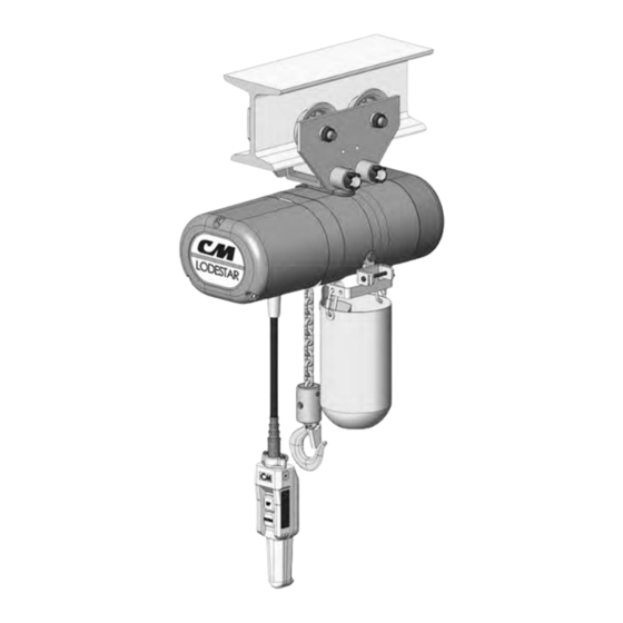
Page 7: Accessories Hook Suspensions
Headroom Trolley Figure 1. Hook Suspensions These are manual push type trolleys (see Figure 3) designed for use with the Lodestar Electric Chain Hoists. A rigid lug LUG SUSPENSION suspension (see Figure 2) is required to suspend the hoist from the trolley. The trolley is adjustable for operation on a Lug suspensions (see Figure 2) are available for all Lodestar range of American Standard “S”... -
Page 8: Latchlok Hooks
This accessory (see Figure 6) is used to hold slack chain CM’s Latchlok hooks (see Figure 5) are available to replace and it is supplied complete with mounting hardware and the standard upper and lower hooks used on the Lodestar instructions. The chain container is recommended for those Electric Hoists. -
Page 9: Recommended Seating Torques For Suspension Adapter Screws
Re-assemble the square collar to the hook shank using the drive pin previously removed. Follow the instructions above, except tighten the captive screw to the recommended seating torque (see Table 2) using a 12 point box type wrench. C. Triple Reeved Units: These hoists have a sheave hanger which is loosely con- nected to the top of the frame by a thin metal plate for ship- ping purposes. -
Page 10: Attaching Load Chain
C C A A U U T T I I O O N N : : Also, do not apply any type of lubricant to the threads of these screws. Lubricating the threads will reduce the effort to seat the screws and as a result, tightening the screws to the INSTALLING THE SERIES 635 LOW (Table 2) recommended torque may break the screw, dam- age the suspension adapter, strip the nuts and/or damage... -
Page 11: Series 635 Low Headroom Side Frame Spacing
Table 3. Series 635 Low Headroom Trolley Side Frame Spacing Standard Load Bracket Standard Load Bracket Standard Load Bracket 3 7/16” Wide 4 3/16” Wide 4 13/16” Wide 2 Ton Capacity 1 Ton Capacity 3 Ton Capacity “X” No. of Spacers No. -
Page 12: Power Supply And Electrical Connections
NOTE: After the unit is connected to the power sup- ply system (see below), suspend a capacity load from the hoist and operate the trolley over the entire High Voltage (Red) length of the runway or monorail system to be sure that the adjustments and operation is satisfactory. -
Page 13: Location Of Components
1. Make temporary connections at the power supply. 2. Operate (UP) control in control station momentarily. If hook raises, connections are correct and can be made permanent. 3. If hook lowers, it is necessary to change direction by interchanging the Red lead and the Black lead of hoist power cord at power supply. - Page 14 SIGNS OF INADEQUATE ELECTRICAL POWER (LOW VOLTAGE) ARE: WARNING Working in or near exposed energized electrical equipment Noisy hoist operations due to brake and/or presents the danger of electric shock. contactor chattering. TO AVOID INJURY: Dimming of lights or slowing of motors connected DISCONNECT POWER AND LOCKOUT/TAGOUT to the same circuit.
-
Page 15: Operating Instructions
SAFETY PROCEDURES Also, if a Lodestar Hoist with a Protector™ is used at unusual For safety precautions and a list of DO’S and DO NOT’S for extremes of ambient temperatures, above 150°F. (106° C.)or safe operation of hoists, refer to page ii. -
Page 16: Inspection
10. DO NOT allow the load to bear against the hook latch. The latch is to help maintain the hook in position while the chain is slack before taking up slack chain. WARNING Allowing the load to bear against the hook latch and/or hook tip can result in loss of load. -
Page 17: Minimum Frequent Inspections
Table 4 Minimum Frequent Inspections Type of Service Item Normal Heavy Severe a) Brake for evidence of slippage. b) Control functions for proper operation. Daily Weekly Monthly c) Hooks for damage, cracks, twists, excessive throat opening, latch engagement and latch operation – see page 12. Weekly Monthly d) Load chain for adequate lubrication, as well as for signs of wear,... -
Page 18: Load
The device has been lubricated and cali- replaced as necessary when replacing worn chain. brated at the factory for a specific model of Lodestar Hoist and is not to adjustable or interchangeable with other mod- Also, these chains are specially heat treated and hardened els. -
Page 19: Maintenance
The Protector™ should operate for the normal life of the times between cleanings. hoist without service. The device has been lubricated and calibrated at the factory for a specific model of Lodestar When lubricating the chain, apply sufficient lubricant to Hoist and is not adjustable or interchangedable with other obtain natural run-off and full coverage. -
Page 20: Electric Brake
Close the switch to energize the 115-1-60/230-1-60 power supply. The light bulb will illuminate if the solid state reverse switch is not damaged. If the bulb fails to illuminate, the switch is damaged and must be replaced. Turn the 115-1-60/230-1-60 power off and remove the solid state reverse switch from the test circuit. -
Page 21: Limit Switches Models A Thru H-2
Figure 17a. Rotatable Limit Switch, Models J thru RRT-2 Figure 17. Limit Switches, Models J thru RRT-2 SETTING UPPER LIMIT SWITCH 1. Limit Switch Sub-Assembly 4. Guide Plate 5. Refer to Table 6-The “A” dimensions given are the mini- 2. Limit Switch Shaft 5. -
Page 22: Recommended Spare Parts
5. Refer to Table 6-The “B” dimensions given are the minimum number of load chain links that should be To insure continued service of the Lodestar Hoist, the follow- set between the loose end link and the hoist frame on ing is a list of parts that are recommended to be kept on the loose end side of the chain. -
Page 23: Troubleshooting
T T R R O O U U B B L L E E S S H H O O O O T T I I N N G G T T a a b b l l e e 7 7 A A l l l l H H o o i i s s t t s s TROUBLE PROBABLE CAUSE... - Page 24 T T a a b b l l e e 7 7 . . ( ( c c o o n n ’ ’ t t ) ) TROUBLE PROBABLE CAUSE CHECK AND REMEDY 4.) Hook raises but will not A.) Open lowering circuit-open or shorted A.) Check electrical continuity and repair or lower.
- Page 25 T T a a b b l l e e 7 7 ( ( c c o o n n ’ ’ t t ) ) Two Speed Hoist TROUBLE PROBABLE CAUSE CHECK AND REMEDY 11.) Hoist will not operate at A.) Open Circuit.
-
Page 26: Electrical Data
ELECTRICAL DATA TO DETECT OPEN AND SHORT CIRCUITS IN ELECTRICAL COMPONENTS. Open circuits in the coils of electrical components may be detected by isolating the coil and checking for continuity with an ohm- meter or with the unit in series with a light or bell circuit. Shorted turns are indicated by a current draw substantially above normal (connect ammeter in series with suspected element and impose normal voltage) or D.C. - Page 27 Table 8. (con’t) Volts- Full Load *D.C. Volts- Full Load *D.C. H.P. Leads H.P. Leads Models Phase- Current Resistance Models Phase- Current Resistance (kW) (kW) Hertz (Amps) (Ohms) Hertz (Amps) (Ohms) T1 to T2 (run) T1 to T2 (run) J,L,R,RT 115-1-60 T3 to T4 (run) 115-1-60...
-
Page 52: Assembly Instructions
ASSEMBLY INSTRUCTIONS HOOK OR LUG SUSPENSION Arrows Must Be Aligned As M M o o d d e e l l s s E E , , H H , , R R , , R R R R , , E E - - 2 2 , , H H - - 2 2 , , R R - - 2 2 a a n n d d R R R R - - 2 2 . . Shown Assemble the dead end bolt and block through the suspen- sion adapter as shown in Figure 19. -
Page 53: Removal And Installation Of Load Chain
hole in the chain block and insert the small end if the pin in c) Detach loose end of load chain from hoist frame, see the hole. Push the pin in by hand until it stops and then use a Figure 7. -
Page 54: Cutting Chains
2. Use a bolt cutter (Figure 22) similar to the H.K. Porter No. 0590MTC with special cutter jaws for cutting hard- Using “Commerical” or other manufacturer’s parts to repair the CM Lodestar Hoists may cause load loss. TO AVOID INJURY: Use only CM supplied replacement parts. Parts may look alike but CM parts are made of specific materials or processed to achieve specific properties. -
Page 56: Limit Switches
When ordering lubricants, specify the type of lubricant, part number and packaged quantity required. Touch-up Paints for Lodestar Electric Chain Hoists and Series 635 Low Headroom Trolleys: 1. Hoist. Order *(1) case (12-12 oz. Aerosol Cans) of Orange Touch-Up paint Part Number 84190. - Page 57 Notes...
-
Page 62: Hoist Lower Hook Components
LODESTAR LOWER HOOK BLOCK ASSEMBLY... - Page 63 L L o o w w e e r r H H o o o o k k B B l l o o c c k k A A s s s s e e m m b b l l y y R R T T , , R R T T - - 2 2 , , A A , , A A - - 2 2 , , A A A A , , J J , , J J - - 2 2 , , J J J J , ,...
- Page 66 Lodestar Hoist Brake Components Models A, A-2, AA, B, B-2, C, C-2, E, E- 2, F, F-2, H, H-2 Models J, J-2, JJ, JJ-2, L, L-2, LL, LL-2, R, R-2, RR, RR-2, RT, RT-2, RRT, RRT-2...
- Page 67 Brake Components Models A, A-2, AA, AA-2, B, J, J-2, JJ, JJ-2, L, L-2, LL, Part Name B-2, C, C-2, F, F-2, LL-2, R, R-2, RR, RR-2, RT, Number Req’d H, H-2 RT-2, RRT, RRT-2 Part number 627-251 Brake Base Plate and Studs 28668 35643 27091...
- Page 68 LODESTAR HOIST LIMIT SWITCH COMPONENTS Models A, A-2, AA, AA-2, B, B-2, C, C-2, E, E-2, F, F-2, H, H-2 Models J, J-2, JJ, JJ-2, L, L-2, LL, LL-2, R, R-2, RR, RR-2, RT, RT-2, RRT, RRT-2...
- Page 69 Limit Switch Components Models A, A-2, AA, AA-2, B, J, J-2, JJ, JJ-2, L, L-2, LL, B-2, C,C-2, E, E-2, F, LL-2, R, R-2, RR, RR-2, RT, Part Name Number Req’d F-2, H, H-2 RT-2, RRT, RRT-2 Part Number Limit Switch Shaft and Gear Kit 27561 36641 627-220...
- Page 70 LODESTAR HOIST GEARING COMPONENTS Models A, A-2, AA, AA-2, B, B-2, C, C-2, E, E-2, F, F-2, H & H-2. Models J, JJ, JJ-2, L, LL, LL-2, R, RR, RR-2, RT, RT-2, RRT & RRT-2.
-
Page 71: Gearing Components
28695 (for Models C, C-2, F, F-2, 36671 (for Models LL, LL-2, RR, RR-2, H & H-2) RRT & RRT-2) Lodestar Protect Kit (Includes item 627-124, 627-321, 627- 322, 627-323, 627-325 & 627-327 for Models A, A-2, AA, AA-2, B, B-2, C, C-2, 2876 (for Models A &... - Page 72 LODESTAR HOIST LIFTWHEEL COMPONENTS Models A, A-2, AA, AA-2, B, B-2, C, C-2, F, F-2, E, E-2, H, H-2 Models J, J-2, JJ, JJ-2, L, L-2, LL, LL-2, R, R-2, RR, RR-2, RT, RT-2, RRT, RRT-2...
-
Page 73: Liftwheel Components
Liftwheel Components Models A, A-2, AA, J, J-2, JJ, AA-2, B, E, E-2, R, R-2, RT, RT-2, JJ-2, L, L-2, Part Name B-2, C, C-2, H, H-2 RR, RR-2 RRT, RRT-2 Number Req’d LL, LL-2 F, F-2 Part Number 627-112 Suspension Adapter Anchor 35066 35015 627-116 Loose End Nut... - Page 74 LODESTAR HOIST MOTOR END COMPONENTS Models A, A-2, AA, AA-2, B, B-2, C, C-2, E, E-2, F, F-2, H, H-2 Models J, J-2, JJ, JJ-2, L, L-2, LL, LL-2, R, R-2, RR, RR-2, RT, RT-2, RRT, RRT-2...
-
Page 75: Motor End Components
Motor End Components A, A-2, AA, AA-2, B, J, J-2, JJ, JJ-2, L, L-2, LL, B-2, C, C-2, E, E-2, F, LL-2, R, R-2, RR, RR-2, RT, Part Name Number Req’d F-2, H, H-2 RT-2, RRT, RRT-2 Part Number 627-113 Identification Plate Contact Factory 627-411 Motor Attaching Screw See Pg. -
Page 76: Contactor Plate Assemblies
CONTACTOR PLATE ASSEMBLIES Part Name Part Number Number Req’d 627-418 Capacitor 27716 627-439 Solid State Reversing Switch 27257 627-650 Hoist Reversing Contactor 28553 (115 Volt Coil) 627-1001 Contactor Mounting Plate 31633 627-1050 Terminal Strip 29014 627-1051 Terminal Strip End Clamp 29015 627-1052 Din Rail Mounting Bracket 29312... - Page 77 CONTACTOR PLATE ASSEMBLIES Part Name Part Number Number Req’d 627-418 Capacitor 27716 627-439 Solid State Reversing Switch 27257 28545 (48 Volt Coil) 627-650 Hoist Reversing Contactor 28552 (24 Volt Coil) 627-1001 Contactor Mounting Plate 31633 627-1003A Ground Label 20940 627-1050 Terminal Strip 29014 627-1051...
- Page 78 CONTACTOR PLATE ASSEMBLIES Part Name Part Number Number Req’d 627-418 Capacitor 27716 627-439 Solid State Reversing Switch 27257 28553 (110 Volt Coil) 627-650 Hoist Reversing Contactor 28545 (48 Volt Coil) 28552 (24 Volt Coil) 627-1001 Contactor Mounting Plate 31633 627-1003A Ground Label 20940 627-1050 Terminal Strip...
- Page 79 CONTACTOR PLATE ASSEMBLIES *CM Terminal Pin Extraction Tool Can Be Ordered To Remove Individual Wires From Harness Connector. Part Name Part Number Number Req’d 24799 (110 Volt Coil 627-650 Hoist Reversing Contactor 24797 (48 Volt Coil) 28860 (24 Volt Coil) 627-1001 Contactor Mounting Plate 31633...
- Page 80 CONTACTOR PLATE ASSEMBLIES Part Name Part Number Number Req’d 28553 (115 Volt Coil) 627-650 Hoist Reversing Contactor 24797 (48 Volt Coil) 28860 (24 Volt Coil) 28870 (115 Volt Coil) 627-800 Hoist Speed Selecting Contactor 28871 (48 Volt Coil) 28878 (24 Volt Coil) 627-1001 Contactor Mounting Plate 31633...
- Page 81 CONTACTOR PLATE ASSEMBLIES Part Name Part Number Number Req’d 24799(115 Volt Coil) 627-650 Hoist Reversing Contactor 24797 (48 Volt Coil) 28860 (24 Volt Coil) 627-1001 Contactor Mounting Plate 31633 627-1003A Ground Label 20940 627-1050 Terminal Strip 29014 627-1051 Terminal Strip End Clamp 29015 627-1052 Din Rail Mounting Bracket...
- Page 82 CONTACTOR PLATE ASSEMBLIES Part Name Part Number Number Req’d 627-418 Start Capacitor 35279 627-418A Run Capacitor 35278 627-423 Start/Run Capacitor Mounting Clamp 35268 627-424 Mounting Clamp Screw 982873 27142 (115 Volt Coil) 627-650 Hoist Reversing Contactor 27138 (48 Volt Coil) 27139 (24 Volt Coil) 627-1001 Contactor Mounting Plate...
- Page 83 CONTACTOR PLATE ASSEMBLIES Part Name Part Number Number Req’d 627-418 Start Capacitor 35279 627-418A Run Capacitor 35278 627-423 Start/Run Capacitor Mounting Clamp 35268 627-424 Mounting Clamp Screw 982873 27013 (115 Volt Coil) 627-650 Hoist Reversing Contactor 27104 (48 Volt Coil) 27105 (24 Volt Coil) 627-1001 Contactor Mounting Plate...
- Page 84 CONTACTOR PLATE ASSEMBLIES *CM Terminal Pin Extraction Tool Can Be Ordered To Remove Individual Wires From Motor/Harness Connector. Part Name Part Number Number Req’d 627-528 Transformer Mounting Screw 982688 29734 (115 V Secondary) 29756 (48 V Secondary) 29809 (24 V Secondary) 627-530 Transformer 29811 (115 V Secondary with Thermal Cutout)
- Page 85 CONTACTOR PLATE ASSEMBLIES Part Name Part Number Number Req’d 627-528 Transformer Mounting Screw 982688 29734 (115 V Secondary) 29756 (48 V Secondary) 29809 (24 V Secondary) 627-530 Transformer 29811 (115 V Secondary with Thermal Cutout) 29983 (48 V Secondary with Thermal Cutout) 29982 (24 V Secondary with Thermal Cutout) 24799 (115 Volt Coil) 627-650...
- Page 86 CONTACTOR PLATE ASSEMBLIES Key Number Part Name Part Number Req’d 627-528 Transformer Mounting Screw 982688 29734 (115 V Secondary) 29756 (48 V Secondary) 29809 (24 V Secondary) 627-530 Transformer 29811 (115 V Secondary with Thermal Cutout) 29983 (48 V Secondary with Thermal Cutout) 29982 (24 V Secondary with Thermal Cutout) 24799 (115 Volt Coil) 627-650...
- Page 87 CONTACTOR PLATE ASSEMBLIES Part Name Part Number Number Req’d 627-528 Transformer Mounting Screw 982688 29807 (115 V Secondary) 29805 (115 V Secondary with Thermal Cutout) 627-530 Transformer 29789 (48 V Secondary with Thermal Cutout) 29984 (24 V Secondary with Thermal Cutout) 24799 (115 Volt Coil) 627-650 Hoist Reversing Contactor...
- Page 88 CONTACTOR PLATE ASSEMBLIES Part Name Part Number Number Req’d 627-528 Transformer Mounting Screw 982688 29807 (115 V Secondary) 29805 (115 V Secondary with Thermal Cutout) 627-530 Transformer 29789 (48 V Secondary with Thermal Cutout) 29984 (24 V Secondary with Thermal Cutout) 24799 (115 Volt Coil) 627-650 Hoist Reversing Contactor...
- Page 89 NOTES...
-
Page 90: Control Station Components
LODESTAR HOIST CONTROL STATION 627-450 Complete Control Cord and Station Assembly Single Spoeed Hoist Control Station S S i i n n g g l l e e S S p p e e e e d d H H o o i i s s t t C C o o n n t t r r o o l l S S t t a a t t i i o o n n K K e e y y N N o o . - Page 91 627-450 Complete Control Cord and Station Assembly Two Speed Hoist Control Station T T w w o o S S p p e e e e d d H H o o i i s s t t C C o o n n t t r r o o l l S S t t a a t t i i o o n n K K e e y y N N o o .
- Page 92 627-450 Complete Control Cord and Station Assembly Four Directional Hoist Control Station F F o o u u r r D D i i r r e e c c t t i i o o n n a a l l C C o o n n t t r r o o l l S S t t a a t t i i o o n n K K e e y y N N o o .
- Page 93 NOTES...
-
Page 94: Trolley Components
SERIES 635 LOW HEADROOM TROLLEY PARTS LIST Figure 27. 1 and 2 Ton Series 635 Low Headroom Trolley Exploded View No. Req’d. Part Number No. Req’d. Part Number Key No. Part Name Key No. Part Name 1 Ton 2 Ton 1 Ton 2 Ton 1 Ton... - Page 95 Figure 28. 3 Ton Series 635 Low Headroom Trolley Exploded View Key No. Part Name Part Number Required 635-1 Side Frame-Plain Side 36696 For 4.0” Thru 5.63” Flange Widths, 36629 For Over 5.63” Thru 7-¼” (Does Not Include Wheels) Flange Widths. If Frame is Equipped With Trolley Guards, Contact Factory. 635-4 TrackWheel Plain 39002...
- Page 96 ® Note: When ordering parts, always furnish hoist model and serial number, motor horsepower, voltage, phase, frequency and rated capacity of hoist on which the parts are to be used. For the location of the nearest CM Master Parts Depot, see the list located on the inside front cover. LIMITATION OF WARRANTIES, REMEDIES AND DAMAGES THE WARRANTY STATED BELOW IS GIVEN IN PLACE OF ALL the use of the goods if, prior to such damage, injury or loss, such...
Need help?
Do you have a question about the CM Hoist and is the answer not in the manual?
Questions and answers