Table of Contents
Advertisement
Quick Links
Download this manual
See also:
Instruction Manual
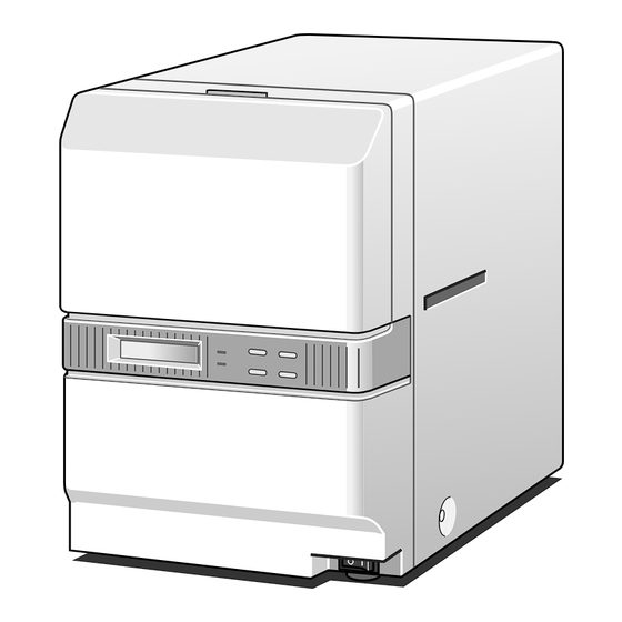
DNP
LAMINATOR FOR CARD PRINTER
SPECIFICATIONS
Item
Transfer method
Transfer time
Usage environment
Storage environment
Power supply
Power consumption
Unit mass
Compatible specification
Accessories
Option
Changes may be made to the specifications and external appearance of this machine for product improvement
without prior notice.
SERVICE MANUAL
CL-500
Content
Halogen lamp built-in heat roller method
Approx. 20 seconds
The time varies according to settings.
Temperature 15°C - 30°C
Humidity 30 % - 70% (without condensation)
Temperature –15°C - 55°C
Humidity 20 % - 80%
AC 100 V - 120 V (tolerance ±10%)
Approx. 200 W
Approx. 9 kg
VCCI-B
Power cord x 2 (for Europe and US market)
Instructions
Unit joining plate
Cleaning card x 1
Cleaning card set x 1 [10p/set (CX210-CC1)]
KAS-T078-005
July 2007
Advertisement
Table of Contents

Subscribe to Our Youtube Channel
Related Manuals for DNP CL-500

Summary of Contents for DNP CL-500
-
Page 1: Specifications
SERVICE MANUAL LAMINATOR FOR CARD PRINTER CL-500 SPECIFICATIONS Item Content Transfer method Halogen lamp built-in heat roller method Transfer time Approx. 20 seconds The time varies according to settings. Usage environment Temperature 15°C - 30°C Humidity 30 % - 70% (without condensation) Storage environment Temperature –15°C - 55°C... -
Page 2: Table Of Contents
CONTENTS IMPORTANT SAFETY PRECAUTIONS ASSEMBLY DIAGRAM AND PARTS TABLE ......33 MODEL NAME ................. 1 IMPORTANT ................33 1. DETAILED SPECIFICATION ............1 MECH ASSY (PLATE R ASSY) ..........34 SCHEMATIC DIAGRAM ............MECH ASSY (CENTER FRAME ASSY) ........35 MECH ASSY ................ -
Page 3: Important Safety Precautions
SAFETY PRECAUTION Important Safety Precautions Prior to shipment from the factory, JVC products are strictly inspected to conform with the recognized product safety and electrical codes of the countries in which they are to be sold. However, in order to maintain such compliance, it is equally important to implement the following precautions when a set is being serviced. - Page 4 SAFETY PRECAUTION • Safety Check after Servicing Examine the area surrounding the repaired location for damage or deterioration. Observe that screws, parts and wires have been returned to original positions, Afterwards, perform the following tests and confirm the specified values in order to verify compliance with safety standards.
-
Page 5: Model Name
MODEL NAME MODEL NAME Alphabets and numbers after the model name indicate the different destinations and specifications. ID label display: CL-500*1-DN 1. DETAILED SPECIFICATION *1 : Destination None : For Japan (100 V specification) : For North America (100 V – 120 V specification) : For Europe (100 V –... -
Page 6: Schematic Diagram
SCHEMATIC DIAGRAM SCHEMATIC DIAGRAM AC 100 V/200 V switching model Card insert detection sensor (Board) Laminate position External machine CN11 Interlock switch sensor (Board) IF connector When the interlock switch is turned off Card ejecting sensor (cassette is removed), the 24 V power (Board) supply for the motor is switched off, all motor stops and the heater is turned off. -
Page 7: Main Components Layout Diagram
MAIN COMPONENTS LAYOUT DIAGRAM MAIN COMPONENTS LAYOUT DIAGRAM 1. FRONT : HEAT ROLLER, TRANSPORT ROLLER AND SENSORS Thermostat Film mark sensor and end mark sensor Heat roller Thermistor Card ejecting sensor Halogen heater Laminate position sensor Card insert detection sensor... -
Page 8: Rear: Motor, Fan, Sensors And Switches
MAIN COMPONENTS LAYOUT DIAGRAM 2. REAR : MOTOR, FAN, SENSORS AND SWITCHES Film reeling motor Cassette interlock SW Heater cam motor Film FG sensor Heat roller pressure position sensor Card cooling fan Heat roller standby position sensor Card transport motor AC select switch Back fan... -
Page 9: Various Circuit Boards And Power Supply
MAIN COMPONENTS LAYOUT DIAGRAM 3. VARIOUS CIRCUIT BOARDS AND POWER SUPPLY Power unit Front board Transformer Protective board AC board Main board AC select SW board... -
Page 10: Removing Main Parts
REMOVING MAIN PARTS REMOVING MAIN PARTS 1. REPLACING HEATER 2. REMOVING EXTERNAL PARTS AND WIRING REFERENCE Å 1) Remove two screws and remove the protective sheet. DIAGRAM ı 2) Remove one screw , shift the connect base a little 2.1 REMOVING COVER and remove the hook on the inner right hand side to remove the halogen lamp. -
Page 11: Wiring Reference Diagram
REMOVING MAIN PARTS 2.3 WIRING REFERENCE DIAGRAM 1) Refer to this photograph and each assembly diagram to organize the wiring. - Page 12 REMOVING MAIN PARTS...
-
Page 13: Removing Main Parts
REMOVING MAIN PARTS 3.1.2 Separating Chassis and Mechanical Unit 3. REMOVING MAIN PARTS ⁄ ¤ 1) To separate mechanical ASSY and bottom 3.1 SEPARATING CHASSIS AND ME- chassis , check that all connectors are removed, CHANICAL UNIT Å then remove eight screws and pull up the ASSY. -
Page 14: Removing Mechanical Main Parts
REMOVING MAIN PARTS 3.2.2 Removing Heater Unit and Heater ASSY 3.2 REMOVING MECHANICAL MAIN PARTS 1) Referring to 3.2.1, remove the feed motor ASSY 3.2.1 Removing Feed Motor Å remove two screws and take out the photo sen- 1) Refer to the assembly diagram to unravel the wir- sor bracket. -
Page 15: Removing Heat Roller
REMOVING MAIN PARTS 3.2.4 Removing Transport Roller 1) Referring to 3.2.1, remove the feed motor and other KJJ46271-003 peripheral parts. 2) After removing two guides , remove four screws Inset Diagram 1 Å and take out the card guide IN ASSY and card Apply lots of heat resistance grease. -
Page 16: Using Service Mode
USING SERVICE MODE USING SERVICE MODE “User Mode” is used for operating settings. “Service Mode” is used for service and maintenance purposes. Setting modes MENU ENTER Normal User Mode setting Setting value operation state item selectable state selectable state EXIT EXIT to select item. -
Page 17: Service Mode
USING SERVICE MODE The card cooling fan does not rotate when laminating The card cooling fan rotates when laminating(Air flow:Low) The card cooling fan rotates when laminating(Air flow:Half) Half Card Fan The card cooling fan rotates when laminating(Air flow:High) High The card cooling fan rotates when laminating(Air flow:Full) Full 0sec... -
Page 18: Firmware Update
(1) Connect the laminator and printer with the Laminator communication cable. [The connect position of printer is different from usually. Before operating update, connect the cable between OPTION1(printer) and PRINTER(laminator) as drawing below; ] CX210 CL-500 SCSI OPTION1 PRINTER (DSUB15) - Page 19 USING SERVICE MODE 3.2 Connecting with CX-120 and CX-1** series (1) Connect the laminator and printer with the Laminator communication cable same as usual. CX-120 (CX-1** series) CL-500 LAMINATOR PRINTER (DSUB9) (DSUB9) (Back view) Fig. 2 (2) Turn on the power of laminator.
- Page 20 USING SERVICE MODE 3.3 Connecting with CX-320 and CX-3** series (1) Connect the laminator and printer with the Laminator communication cable same as usual. CX-320 (CX-3** series) CL-500 OPTION2 PRINTER (DSUB9) (DSUB9) (Back view) Fig. 3 (2) Turn on the power of laminator.
-
Page 21: Mechanism Operation
MECHANISM OPERATION MECHANISM OPERATION 1. INITIAL OPERATION Stage: Heat roller pressing operation The heater cam motor is rotated and stops when a Initial Operation when Power On slit arrives at the heat roller pressure position sen- 1. Stop every motor and turn off the heater. sor. - Page 22 MECHANISM OPERATION 2.1 When Cool Time is set Using 0.6mil, Overlay Using 1mil After the film position search is finish, the card is After the film position search is finish, the card is moved to the position that is detected by the card returned to the position that is detected by the card eject sensor.
-
Page 23: Troubleshooting
TROUBLESHOOTING TROUBLESHOOTING 1. HANDLING ERROR CODES Error Content/Text Displayed Error Detection Action Parts to be replaced Card Jam (near the card When feeding card from the en- Check the setup condition. During sensor operation error entrance) trance, the card does not arrive Check the operation of the card During card entrance sensor entrance sensor using the sen-... - Page 24 TROUBLESHOOTING Error Content/Text Displayed Error Detection Action Parts to be replaced Heat roller over Heat roller temperature is de- If the error occurs during a heat Main board, or AC board, thermo- heat tected with the heat roller thermo- roller temperature control circuit stat, or main board.
- Page 25 TROUBLESHOOTING Error Detection Action Parts to be replaced Error Content/Text Displayed Cannot enter Cleaning Heat roller temperature is detected If the error occurs when the heat Thermostat, or main board, or Mode with the heat roller thermostat. roller temperature is below 50˚C, connection cable.
-
Page 26: Handling Card Jam
TROUBLESHOOTING 2. HANDLING CARD JAM When a card not suitable for laminating is used in the laminator or when inappropriate laminating conditions are set, the card may be warped or curled drastically by the laminating heat and cause a jam in the laminator. Follow the steps below to remove the card. - Page 27 TROUBLESHOOTING When the jam cannot be resolved in such state, follow the steps below to remove it. Remove six screw B and remove the top cover. The guide is held by claws on the front panel. Push in the guide and lift up to remove. The protective sheet is inserted by claws in the card guide out ASSY.
-
Page 28: Handling The Situation Where Power Supply Is Cut Off When The Heat Roller Is Down
TROUBLESHOOTING 3. HANDLING THE SITUATION WHERE POWER SUPPLY IS CUT OFF WHEN THE HEAT ROLLER IS DOWN When power supply is cut off in a power failure during laminating or when the front door is open and the cassette is pulled out by mistake, the heat roller is lowered and the heat causes damage to the film and card. -
Page 29: Set Up Guide
SET UP GUIDE SET UP GUIDE CL500 series Card Laminator is using heat press roller system to the surface of the card. It is important to do best setting to securing sufficient adhesive strength and minimum warp of the card, by heating occurs at the time of lamination. This guide explains the method of a set up in the case of laminating on the card which is printed by CX-320 (CX210 ans CX-3** series) or CX-120 (CX-1** series). - Page 30 Film 1mil 0.6mil overlay Surrounding temperature 15 – 25°C 26 – 30°C 15 – 30°C 15 – 30°C CL-500 Temp 170°C 155°C 130°C Speed 5.5mm/s 8.5mm/s 8.5mm/s Card fan...
-
Page 31: Setting Process
SET UP GUIDE 2. SETTING PROCESS We will recommend the condition setting to be tested after about 20 minutes have passed since it started. [There is no Bend Remedy function of the card in CX-120 (CX-1** series).] <NOTE> CX-320 including CX210, CX-320 and CX-3** series. CX-120 including CX-120 and CX-1** series. -
Page 32: Various Conditional Settings
Diagram 1. In consideration of such characteristic, temperature and speed conditions are defined in CL-500 default settings to minimize warping while ensuring the adhesiveness. The required transfer energy for adhesion is according to the thickness of the film to be transferred and follows the order of overlay<0.6mil patch<1mil patch. - Page 33 SET UP GUIDE 3) Card fan : Card Fan During laminating, the reverse side of the card (the side that is not laminated) is cooled. Usually, the setting is OFF but when the convexity is very prominent on the laminated side, the fan is set to LOW or more to prevent the card from warping.
-
Page 34: Card Adhesiveness
SET UP GUIDE 4. CARD ADHESIVENESS The laminate adhesiveness to the card is evaluated as below. Always evaluate the adhesiveness when changing conditional settings for transfer temperature. (1) Patch film Card folding test : 1) Fold the card equally into two and press hard at the folded line. 2) Unfold and fold along the folded line in the opposite side, and press hard at the folded line. -
Page 35: Maintenance
Depends on the usage environment QAR0445-001 (KEF1043) Air intake fan 40,000 hours QAR0429-001 (KEF1037) Card cooling fan 20,000 hours Only during laminating CL-500-M01 Heater pressure motor 200,000 screens CL-500-M01 Ink reeling motor 100,000 screens QAR0444-001 (KBM1036) Card transport motor 200,000 screens... -
Page 36: Adjustment
ADJUSTMENT ADJUSTMENT Adjustment 1. ARRANGEMENT OF ADJUSTMENT VOLUME MAIN PWB REAR TP11 5VREF VR1 : Adjustment of +5V MAIN PWB VR2 : Sensitivity adjustment of End Mark Sensor 2. HOW TO ADJUST THE VOLUME 1) Adjustment of VR1 (+5V) TEST POINT 5VREF - GND 5V ±... -
Page 37: Assembly Diagram And Parts Table
ASSEMBLY DIAGRAM AND PARTS TABLE ASSEMBLY DIAGRAM AND PARTS TABLE Important Symbol indicates that safety issues are important for this part. When replacing parts, always use the specified part for safety reasons. Do not supply parts not described in the parts table or parts displayed with a - sign in the parts column. Parts for repair are at standard price (exclusive of tax). -
Page 38: Mech Assy (Plate R Assy)
ASSEMBLY DIAGRAM AND PARTS TABLE MECH ASSY (PLATE R ASSY) CL-500-SB1 QYREE 4000X SLIDE BOBBIN SA Q03093 -837 QYREE 4000X QYREE 4000X (CL-500-SB1) SLIDE BOBBIN SA KJJ46271 KJJ46271 -003 -003 (TPS0235-001-E) KJJ46271 -003 KJJ46271 -003 KJJ46271 KJJ46271 -003 -003 KJJ46271... -
Page 39: Mech Assy (Center Frame Assy)
ASSEMBLY DIAGRAM AND PARTS TABLE MECH ASSY (CENTER FRAME ASSY) Paste After inserting the connector, ensure that the wires are stored neatly. (Insert the red wire first.) Check part number TPS0235- 001-F (3p side) KWS0718-001 CN501 CN502 QYSPSP (2p side) H3012NA x2 KWR18202-001 E-DN only... -
Page 40: Mech Assy
ASSEMBLY DIAGRAM AND PARTS TABLE MECH ASSY Inset Diagram 1 Insert the front plate inside the rear plate. KJJ46271-003x2 17613-001 Clamp KJJ46271 -003 x2 Clamp to the wire clamp of the center plate KJJ46271 Clamp -003x3 (Front) Pull tightly CDI,LAM Inset Diagram 2 After combining the FRAME, paste the BRUSH. -
Page 41: Card Guide In Assy
ASSEMBLY DIAGRAM AND PARTS TABLE CARD GUIDE IN ASSY QYSDSF3008NA x2 Inset Diagram 2 (KEP4101-B) Inset Diagram 1 QYSDSF3008NA x2 QYREE3000X G.NO.002 Only QYREE3000X Inset Diagram 2 QYREE3000X (KEP4101-B) Inset Diagram 1 Insert the sensor sheet between the mold and sensor when installing the sensor board. -
Page 42: Card Guide Out Assy
ASSEMBLY DIAGRAM AND PARTS TABLE CARD GUIDE OUT ASSY Inset Diagram 1 Inset Diagram 2 QYSDSF Inset Diagram 2 TPS0235 3008N x2 Insert the sensor sheet between -001-B the mold and sensor when installing the sensor board. QYREE3000X Inset Diagram 1 QYREE3000X QYREE3000X Taper side... -
Page 43: Media T Up Motor Assy
KJJ46271-003 (Apply evenly) M M − 0 6 REVISED Price SYMBOL PART NO. PART NAME DESCRIPTION (yen) PART NO. Rev. CL-500-M01 MOTOR KJP34284-B0A T.UP MTR BKT ASY KJY32775-021 BEARING KJM46627-00A ENCODE GEAR ASY KJM45492-001 DOUBLE GEAR QYSPSPL3004NA ASY SCREW QYREE3000X E. -
Page 44: Heater Motor Assy
Check part number M M − 0 7 REVISED Price SYMBOL PART NO. PART NAME DESCRIPTION (yen) PART NO. Rev. CL-500-M01 MOTOR ASY KJP34282-A0A PRESS MTR BKT ASY KJY32775-021 BEARING KJM46475-001 WORM WHEEL 2 KJM45507-001 DOUBLE GEAR QYSPSPL3004NA ASY SCREW QYREE4000X E. -
Page 45: Heater Assy
Hook the claw section, press it against the plate and tighten the screws. M M − 0 8 REVISED Price SYMBOL PART NO. PART NAME DESCRIPTION (yen) PART NO. Rev. CL-500-HR1 HEAT ROLLER ASY KUU107J-102 THERMISTOR ASY CL-500-TS1 THERMOSTAT ASY KLA5005-121 HEATER TSS0227-1/2... -
Page 46: Heater Unit
ASSEMBLY DIAGRAM AND PARTS TABLE HEATER UNIT QYREE6000X KJJ46271-003 Apply lots of heat resistance grease. Inset Diagram 1 QYREE3000X Install after installing the cover and main machine QYREE6000X Inset Diagram 2 Wiring Long Apply a thin coat of grease on the Short outside of the BKT shaft hole, thread through the shaft and... -
Page 47: Feed Motor Assy
ASSEMBLY DIAGRAM AND PARTS TABLE FEED MOTOR ASSY QYSPSPH3006NA QYSPSPH3006NA QYSPSPH3006NA QYSPSPH3006NA Tap hole QYSPSPH QYSPSPH 3006NA 3006NA KJJ46271-003 QYSPSPH Tap hole 3006NA QYSPSPH KJJ46271-003 QYSPSPH 3006NA 3006NA QYSPSPH3006NA Tap hole Take note of the direction when installing Ensure that the Ensure that the extracting hole extracting hole... -
Page 48: Feed Roller Assy
ASSEMBLY DIAGRAM AND PARTS TABLE FEED ROLLER ASSY QYREE6000X QYREE5000X x4 (TSS0223) Coat with grease Apply thread lock and tighten the screw. QYREE6000X Tighten with extra torque. (Tighten hard to ensure that it is not loose) QYYASPW4004F Thread the wire back and forth the roller as shown in the diagram. -
Page 49: Ac Block Assy
ASSEMBLY DIAGRAM AND PARTS TABLE AC BLOCK ASSY For E-DN KWS0720-001 For E-DN QYSPSPH4008NA x2 For DN KWS0715 KWS0721-001 -001 KWR17704-001 For E-DN Check part number For DN KWS0722-001 KJJ46271-003 x2 (TPS0235-001-A) M M − 1 3 REVISED Price QTY G.No. SYMBOL PART NO. -
Page 50: Bottom Assy
ASSEMBLY DIAGRAM AND PARTS TABLE BOTTOM ASSY Inset Diagram 4 KJJ46271-003 KEP4101-G Inset Diagram 4 KJJ46271 -003 Check part number Ensure that the faston is tightly and securely inserted. KWS0713-002 Inset Diagram 1 KJJ46271 -003 Inset Diagram 2 KWS0712-001 Inset Diagram 3 Torque management QYSPSPH 4016NA x4... -
Page 51: Mech Frame Assy
ASSEMBLY DIAGRAM AND PARTS TABLE MECH FRAME ASSY Install the GUIDE after KJJ46271-003 x2 KJJ46271-003 x2 installing the HEATER. (TSS0224) Paste KJJ46271 -003 x2 QYSDSP (TSS0225) Inset 3006NA x2 Diagram 2 (TSS0227) Inset Diagram 1 HR1,HR2 Inset Diagram 2 Tighten the fix screws Inset x 3 on the rear side Diagram 1... - Page 52 ASSEMBLY DIAGRAM AND PARTS TABLE MECH FRAME ASSY Check that the heater rises naturally when Trail the wire so that it does not you release your hand after pressing down touch the tip of the screws. Ensure the heater on the front side. that the heat resistance binder is not Thread under CASSETTE SW SA.
- Page 53 ASSEMBLY DIAGRAM AND PARTS TABLE MECH FRAME ASSY Motor wires should not touch the gears Clamp KWS0704-001 KWS0702-001 Clamp Clamp FILMM KWS0703-001 Clamp CAMM Inset Diagram 1 CN13 17502-001 CN201 Clamp Connector black KJJ46271 -003 x4 Clamp Ensure that this is well separated from the platen pulley screw.
-
Page 54: Front Panel Assy (Front)
ASSEMBLY DIAGRAM AND PARTS TABLE FRONT PANEL ASSY (FRONT) Take note of the direction Paste QYSDSF3008NA x2 QYSDSF3008NA x2 QYSSSF3006NA x2 Paste (Do not peel off the protective sheet) M M − 1 6 REVISED Price SYMBOL PART NO. PART NAME DESCRIPTION (yen) PART NO. -
Page 55: Front Panel Assy (Rear)
ASSEMBLY DIAGRAM AND PARTS TABLE FRONT PANEL ASSY (REAR) QYSDSF3008NA x2 QYSDSF3008NA x2 Inset Diagram 2 Inset Diagram 2 QYSDSF3008NA x5 Inset Diagram 1 Mat processing Peel off both sides of the protective sheet (green/transparent). Important) Peel off when protective Glossy surface sheet is attached. -
Page 56: Final Assy (Panel)
ASSEMBLY DIAGRAM AND PARTS TABLE FAINAL ASSY(PANEL) (TFA0021) Paste the manufacturer's number (TFS0125) QYSDSP3006Nx4 Inset Diagram 1 (TFS0126) Insert to shaft Inset Diagram 2 CN02 Inset Diagram 2 Insert to FRONT board CN02 Insert the claws on both sides of the front panel to the plate and fasten with screws. -
Page 57: Final Assy(Rear)
ASSEMBLY DIAGRAM AND PARTS TABLE FINAL ASSY(REAR) Inset Diagram 2 Paste Check that the filter is not misaligned and the wire that fixes the filter is not out of position. Approx. Align with center Inset Diagram 2 QYSDSP3006NA QYSDSP4008NA Inset Diagram 1 Inset Diagram 1 The four locations should be attached to the innermost of the... -
Page 58: Annex Assy
ASSEMBLY DIAGRAM AND PARTS TABLE ANNEX ASSY VM0303B,VM0306B,H05VV-F VM0233,VM0089,VW-1 POWER CORD (200V/EU) POWER CORD (120V/UL) Secure with tape Secure with tape (-011) (-011) Caution sheet Cleaning card Inst manual (-012) Secure with tape Secure with tape (-006) CONNECT PLATE Secure with tape M M - 2 0 REVISED Price... -
Page 59: Final(Packing) Assy
ASSEMBLY DIAGRAM AND PARTS TABLE FINAL(PACKING) ASSY (POWER CORD) (CONNECT PLATE) G.NO.DN . . . AC100-120V G.NO.E-DN AC100-120V/AC220-240V (Instructions) MODEL (Cleaning card) VOLT FREQ. 50/60 Hz 13kg For KXZ44568-001 Inset Diagram 1 Check the printed contents and paste Secure with tape Inset Diagram 1 (TFS0127) [Always operate after the heat roller has cooled down.]... - Page 60 Distributor : DAI NIPPON PRINTING CO.,LTD. 1-1 Icigaya-kagacho, 1-chome Shinjuku-ku, Tokyo 162-8001 Japan Phone : +81-3-3266-3331 Facsimile : +81-3-3266-2732...
Need help?
Do you have a question about the CL-500 and is the answer not in the manual?
Questions and answers