Advertisement
Quick Links
MicroMetl
ECD-SRT12TA-D2, ECD-SRT34TA-D2, ECD-SRT05TA-D2 Series
*QR Code
Read these instructions completely before attempting to install the Vertical
Accessory Ultra Low Leak Economizer.
CONTENTS
Safety Consideration . . . . . . . . . . . . . . . . . . . . .1
General. . . . . . . . . . . . . . . . . . . . . . . . . . . . . . . . . . . .1
Economizer Sensor Usage. . . . . . . . . . . . . . . . . . . . .2
Accessories List. . . . . . . . . . . . . . . . . . . . . . . . . . . . . .2
Wiring Diagrams. . . . . . . . . . . . . . . . . . . . . . . . . . . . . .5-7
Installation . . . . . . . . . . . . . . . . . . . . . . . . . . . . . . . . .2-8
W7220 Menu Structure. . . . . . . . . . . . . . . . . . . . .9-12
Controller Setup and Configuration. . . . . . . .13-15
Operation. . . . . . . . . . . . . . . . . . . . . . . . . . . . . . . .16
Troubleshooting. . . . . . . . . . . . . . . . . . . . . . . . . . . .17
Barometric Relief and Return Pressure
Drop. . . . . . . . . . . . . . . . . . . . . . . . . . . . . . . . . . . . . . . . . . . . .18
*Jade W7220 Controller Addendum
*Certificate of Acceptance
Use QR Code Above to Access
SAFETY CONSIDERATIONS
Installation and servicing of air-conditioning equipment can be
hazardous dur to system pressure and electrical components. Only
trained and qualified service personnel should install, repair, or
service air-conditioning equipment.
Untrained personnel can perform the basic maintenance funtions.
All other operations should be performed by trained service
personnel. When working on air-conditioning equipment, observe
precautions in the literature, tags, and labels attached to the unit,
and other safety precautions that may apply.
Follow allsafety codes. Wear safety glasses and work gloves. Use
quenching cloth for unbrazing operations.
It is important to recognize safety information. This is the safety-
alert symbol
. When you see this symbol on the unit and in
!
instructions or manuals, be alert to the potential for personal injury.
Table 1
Base Chasis/Curb Design (3-23 ton)
Economizer
Package
Unit Chassis
Carrier
48/50TC
Chassis 1
A04,A05,A06,
B04,B05,B06
ECD-SRT12TA
48/50TC
Chassis 2
A07,B07
48/50TC
Chassis 3
A08,D08
ECD-SRT34TA
Chassis 4a
48/50TC
A09,A12,
Chassis 4b
D09,D12,D14
Chassis 5
48/50TC D16 580J,558J 16D RGS,RAS 180 48/50HC D14 581J,551J 14D RGH,RAH 150
ECD-SRT05TA
Chassis 5
N/A
Installation Instructions
48/50TC
Bryant
ICP
Carrier
580J,558J
RGS,RAS
04A,05A,06A,
48/50HC A04
036,048,060
04G,05G,06G
580J,558J
48/50HC
RGS,RAS 072
07A,07G
A05,A06
580J,558J
RGS,RAS
48/50HC A07
08A,08D
090,091
580J,558J
RGS,RAS
48/50HC
09A,12A,
101,102,121
D08,D09
09D,12D,14D
120,150
N/A
N/A
N/A
Accessory Ultra Low Leak Vertical Economizer
Understand the signal words DANGER, WARNING, CAUTION,
and NOTE. These words are used with the safety-alert symbol.
DANGER identifies the most serious hazards which will result
in severe personal injury or death. WARNING signifies hazards
which could result in personal injury or death. CAUTION is used
to identify unsafe practices, which may result in minor personal
injury or product and property damage. NOTE is used to highlight
suggestions which will result in enhanced installation, reliability, or
operation.
Equipment Damage Hazard
Electrostatic discharge can short equipment circuitry. Ensure
that you are properly grounded before handling the unit.
Electrical Shock Hazard
Can cause severe injury, death or property damage. Disconnect
power supply before beginning wiring, or making wiring
connections, to prevent electrical shock or equipment damage.
GENERAL (When ordered with controls)
The system utilizes the latest technology available for integrating
the use of free cooling with mechanical cooling for packaged
rooftop units. The solid-state control system optimizes energy
consumption, zone comfort, and equipment cycling by operating
the compressors when the outdoor-air temperature is too warm,
integrating the compressor with outdoor air when free cooling
is available, and locking out the compressor when outdoor-air
temperature is too cold. Demand control ventilation is supported.
This can be used with single or multiple speed indoor fans.
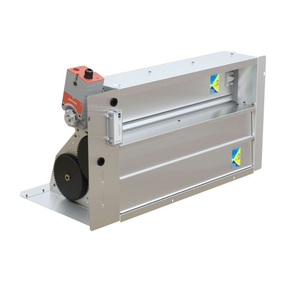
The MicroMetl Ultra Low Leak Economizer utilizes gear-driven
technology with a direct-mount spring return actuator that will close
upon loss of power. When ordering with controls, The Ultra Low
Leak Economizer comes standard with a Mixed Air Sensor (Also
called The Supply Air Temperature Sensor), and the option of
Adjustable Dry Bulb, Enthalpy, Differential Adjustable Dry Bulb, and
Differential Enthalpy Sensors. CO2 and Smoke Detectors Sensor
are an additional field installed option.
48/50HC
48/50LC
Bryant
ICP
Carrier
RGH,RAH
581J,551J 04A
48/50LC A04
036
581J,551J
RGH,RAH
48/50LC
05A,06A
048,060
A05,A06
581J,551J
RGH,RAH
N/A
07A
072
581J,551J
RGH,RAH
48/50LC 07
09D,12D
090,120
48/50LC
08,09,12
N/A
N/A
N/A
1
Small Rooftop Products
Select 3 to 12 ½ Tons
!
CAUTION
WARNING
!
50TCQ
Carrier
Bryant
ICP
50TCQ
548J
RHS
A04,A05
04A,05A
036, 048
50TCQ
548J
RHS
A06,A07
06A,07A
060,072
N/A
N/A
N/A
50TCQ
548J
RHS
D08,D09,D12
08D,09D,12D
090,102,120
N/A
N/A
N/A
50TCQ D14
548J 14D
RHS 150
California
& ASHRAE
Code
Compliant
48/50HCQ
Carrier
Bryant
ICP
50HCQ A04 549J 04A RHH 036
50HCQ
549J
RHH
A05,A06
05A,06A
048,060
50HCQ A07 549J 07A RHH 072
50HCQ
549J
RHH
D08,D09
08D,09D
090,102
N/A
N/A
N/A
50HCQ D12 549J 12D RHH 120
Advertisement

Summary of Contents for MicroMetl ECD-SRT12TA-D2 Series
-
Page 1: Installation Instructions
The MicroMetl Ultra Low Leak Economizer utilizes gear-driven technology with a direct-mount spring return actuator that will close Follow allsafety codes. Wear safety glasses and work gloves. Use upon loss of power. - Page 2 See Table 1 for economizer package usage. See Table 2 for packing contents. Actuator (Hidden) Unpack and inspect economizer contents from carton. Contact MicroMetl immediatly if any parts are missing or damaged. Outside Air Table 2 - Packaging List Temperature Sensor or Assembled Hood with Divider &...
- Page 3 Optional Power Exhaust wired. Apply power to the system and wait sixty minutes before MicroMetl carries a large variety of Power Exhausts. To control the checking for alarms. This allows time for all the configured devices (e.g. sensors, actuator) to become operational. The exception is...
- Page 4 Filter Access Panel Compressor Access Panel Hood Filter Divider Outdoor-Air Opening and Fig. 6A - Hood for Extra Large Cabinet Indoor Coil Access Panel Fig. 4 - Typical Outdoor-Air Section Access Panel Locations HVAC Unit Filters Wiring Harness Hood Top and Side Assembly Insert Economizer...
- Page 5 12. Locate the mixed (supply) air temperature sensor in the the controller / bracket in the top left corner of the unit control economizer hardware bag. Mount the sensor in the indoor box as shown in wiring diagram, Fig. 9 and 10A. Screw in fan section of the unit, see Figure 12.
- Page 6 48TMHSRSE--A20 Harness If using the OA enthalpy accessory, the OAT must be removed. Set sensor dip-switches, See Table 11. Fig. 10A - Typical Wiring Diagram For 1 and 2 Speed Units (2 Speed Diagram Shown)
- Page 7 Fig. 10B - Typical Wiring Diagram For 3 Speed Units (48/50LC 07-12) (See 3 Speed Unit Instructions for Complete Diagram) NOTES: Wires shown in bold are part of harness which is provided with 48/50LC 07-12 3 speed units. Harness which is provided with economizer accessory is not used on 3 speed units.
- Page 9 Thermostat Center Post Connection Access Panel Heating Access Indoor Fan Motor Panel Access Panel Fig. 11 - Typical Indoor Fan Motor Fig. 13 - W7220 Controller Access Panel Locations Press the (Enter) button to accept the displayed value and store it in nonvolatile RAM. “CHANGE STORED”...
- Page 10 IMPORTANT: Table 1 illustrates the complete hierarchy. Your menu parameters may be different depending on your configuration. For example if you do not have a DCV (CO ) sensor, then none of the DCV parameters appear. Table 3 ─ Menu Structure Parameter Parameter Menu...
- Page 11 Table 3 ─ Menu Structure (cont) Parameter Parameter Menu Parameter Default Range and Notes Value Increment STATUS EXH2 OUT ON/OFF Output of AUX1 O terminal; displays only if AUX1 O = EXH2 (CONT.) ON/OFF Output of AUX1 O terminal; displays only if AUX1 O = ERV MECH COOL ON 0, 1, or 2 Displays stage of mechanical cooling that is active.
- Page 12 Table 3 ─ Menu Structure (cont) Parameter Parameter Menu Parameter Default Notes Range and Increment Value SYSTEM AUX2 I SD/W or HP(O)/HP(B) In CONV mode: SETUP SD = Enables configuration of shutdown (default); W = Informs controller that system is in heating mode. In HP O/B mode: HP(O) = energize heat pump on Cool (default);...
- Page 13 Table 3 ─ Menu Structure (cont) Parameter Parameter Menu Parameter Default Notes Range and Increment Value CHECKOUT CONNECT AUX Energizes the AUX output. If Aux setting is: • NONE ─ not action taken • ERV ─ 24 Vac out. Turns on or signals an ERV that the conditions are not good for economizing but are for ERV operation.
- Page 14 Table 4 - Economizer Module - Checkout Tests Left Hand Terminal Blocks Use the Checkout menu (see Table 3) to test the damper operation and any configured outputs. Only items that are configured are Label Type Description shown in the Checkout menu. Top Left Terminal Block NOTE: See User Interface on for information about menu...
- Page 15 Dry Bulb Sensor Economizers are shipped standard with an outside air dry bulb sensor. System default setting (high temp limit) is 63°F, and has a range of 48° to 80°F. Sensor is factory installed on economizer (note: a 2nd sensor is provided for mixed air temperature). Note: California high temperature setting requirements by region are shown below in Table 6.
- Page 16 Table 7 - Single Enthalpy and Dual Enthalpy High Limit Curves Point P1 Point P2 Enthalpy Temp. Temp. Enthalpy Humidity Curve Dry Bulb ( Dewpoint ( (btu/lb/da) Temp ( Humidity %RH Temp ( 80.0 60.0 28.0 80.0 36.8 66.3 80.1 75.0 57.0 26.0...
- Page 17 OPERATION When space temperature demand is satisfied (thermostat Y1 opens), the dampers will return to Minimum Damper position if Cooling, Unit with Ultra Low Leak Economizer indoor fan is running or fully closed if fan is off. For Occupied mode operation of Ultra Low Leak Economizer, here If accessory power exhaust is installed, the power exhaust fan must be a 24-v signal at terminals R and OCC (provided through motors will be energized by the economizer control as the dampers...
- Page 18 1.800.884.4662 (PST) indycustomerservice@micrometl.com longviewcustomerservice@micrometl.com sparkscustomerservice@micrometl.com Manufacturer reserves the right to discontinue, or change at any time, specifications, designs and prices without notice and without incurring obligations. Form No. 18349-2P-A / JCI Form No. 1135765 Copyright MicroMetl Corporation 2014. All rights reserved.
Need help?
Do you have a question about the ECD-SRT12TA-D2 Series and is the answer not in the manual?
Questions and answers