Advertisement
Quick Links
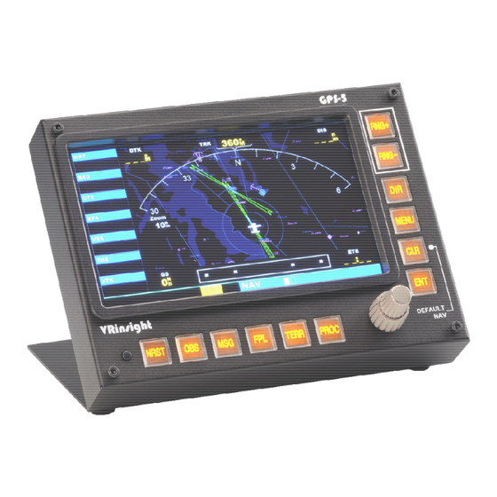
GPS 5 panel
USER MANUAL
(MEO2.520-27MAY2010)
Please read this manual before operating your
units and keep it for future reference.
VRinsight
Virtual Reality Insight
All stated here is subject to change without advanced notice for improvement.
Tel : +82-31-284-7090~91 Fax : +82-31-284-7092 E-mail :
tech@vrinsight.com
Web site : www.vrinsight.com
1
Advertisement

Summary of Contents for VRinsight GPS-5
- Page 1 Please read this manual before operating your units and keep it for future reference. VRinsight Virtual Reality Insight All stated here is subject to change without advanced notice for improvement. Tel : +82-31-284-7090~91 Fax : +82-31-284-7092 E-mail : tech@vrinsight.com Web site : www.vrinsight.com...
- Page 2 NOTE : This manual could be redistributed unless you modify the contents. This manual has been written out on a Serial FP v2/Jet Liner’s GPS-5 basis. All software (& software versions) stated here (MEO2.520-16APR2010) is Subject to change without advanced notice for improvement.
- Page 3 It is the most fundamental approach guide into the airports inaccessible in IFR conditions. Real shape & full functionality of GPS-5 supports all default aircrafts & add-on aircrafts. It is completely interfaced with MSFS9 and MSFSX through interfacing application software “SerialFP2”...
- Page 4 Features • Realistically shaped and fully functional buttons, dual knob and LCD • LCD size : 15cm (L) X 8.8cm (W) / 7 inch • Fully metal cases • Standalone type • Available in Window mode only • One year warranty Technical specifications •...
- Page 5 Before use GPS-5, please check below procedures. SerialFP2 Installation In the GPS-5 package, one “Install DVD” is included. When you insert it in DVD driver of your computer, “VRinsight HTML” document will be shown. Then click “SerialFP2” (operating software) and install it at a proper folder.
- Page 6 Double click the shortcut of “SerialFP2” or find it in “All programs” of “Start menu . If everything is done properly, below window will be shown.
-
Page 7: Monitor Setting
1. Check the current display properties in order that another sub monitor is connected or not. (See “Settings”) 2. Connect video cable of GPS-5 to your computer. 3. Connect AC/DC adaptor to your GPS-5. 4. Check the display properties in order that GPS-5 monitor is detected or not. - Page 8 * If the GPS-5 monitor (=Monitor 2) isn’t detected, check the connection of video cable & AC/DC adaptor. * If your OS is VISTA, please restart your computer. 5. When the GPS-5 monitor is recognized, click monitor 2(=GPS-5 monitor). 6. Adjust the resolution for GPS-5 monitor.
- Page 9 * If GPS-5 monitor doesn’t illuminate, restart your computer. 10. Click “Apply” and click “OK” 11. If everything is done properly, GPS-5 will be power on. 12. Multiple display & Monitor rotation setting 12-A. NVIDIA 12-A-1. Launch “NVIDIA Control Panel”.
- Page 10 12-B. ATI 12-B-1. Launch “Catalyst(TM) Control Center”. The monitor of GPS-5 will automatically display your “Desktop” view. 12-B-2. Go to “Displays Properties” and select monitor 2.
- Page 11 GPS-5 controls explanation LCD display Shows all information about GPS-5 Buttons Buttons are used to input & assign the data and enter the pages Buttons Programmable button Dual knob : Input alphabet & number...
- Page 12 RNG+ Allows the pilot to select the desired map range. Use the up arrow to zoom out to a larger area, or the down arrow to zoom in to a smaller area RNG- Provides access to the direct-to function, which allows the pilot to enter a destination waypoint and establishes a direct course to the selected Destination.
- Page 13 Allows the pilot to create a three-dimensional profile which provides guidance to a final (target) altitude at a specified TERR location Allows the pilot to select and remove approaches, departures, and arrivals from the flight plan. When using a flight plan, available procedures for the PROC departure and/or arrival airport are offered automatically.
- Page 14 Panel installer launch : Panel installer will copy & paste all necessary panel data to work GPS-5 automatically. Be sure “Panel Installer” should run before running SerialFP2. * Once the panel is installed, aircraft configuration is kept. After “SerialFP2” installation, you can find “Panel Installer”.
- Page 15 1. MSFS-Root Path : Browse the path where “Flight Simulator 9” or “Microsoft Flight Simulator X” is installed. * If “Flight Simulator 9” or “Microsoft Flight Simulator X” is installed other “Drive” or “Directory”, find the path and click “OK”. * if you select a wrong path, “Status”...
- Page 16 2. VRinsight panel : Drop down and select your panel. 3. Aircraft : Drop down and select your aircraft. 4. Run : Copy & paste all necessary panel data to work GPS-5 automatically. * If you select an aircraft for FS9 and the “MSFS-Root Path” is for FSX, “Status”...
- Page 17 5. Status : Inform current status. * If everything is done properly, you will get below message...
- Page 18 Preparing GPS-5 before Flight (With Cessna 172) Step 1 : Initial check up Before flight with GPS-5, please check the followings are done A. Install of SerialFP2. * Check that “Install USB-Serial Driver” is checked or not. B. Confirm the USB connection.
- Page 19 7 : Input test for panel 8 :Link test for panel with game Step 5. Press “Load FS Module” to move undocked GPS display to GPS-5. Step 6. Input the X & Y position and size of GPS-5 monitor and press “Redraw”.
- Page 20 8, Put W=768, Y=1280. Step 7. Confirm the GPS display has been moved to GPS-5. Then press “Save” for future purpose. With “Panel Config” window, you can adjust position and size of the display. See how to control them.
- Page 21 X, Y Current position of gauges display window ++ U Moves gauges display window to up ++ D Moves gauges display window to down ++ L Moves gauges display window to left ++ R Moves gauges display window to right W, H Current size of gauges display window ++ H...
Need help?
Do you have a question about the GPS-5 and is the answer not in the manual?
Questions and answers