Table of Contents
Advertisement
Quick Links
Introduction:
The model should be assembled following the sequence of the stages of construction described in these instructions.
The laser-cut components are individually numbered. The manufacturing method leaves small tabs on some parts which
have to be cut away using a thin-bladed modelling knife. The dark edges of the laser-cut parts should be rubbed off using
abrasive paper in order to obtain sound glued joints. Check that all components fit accurately before reaching for the glue,
and carry out any minor trimming required. Allow all glued joints to dry out fully before starting the next stage of
construction. We recommend a fast-setting white glue for all joints. If water-soluble glue is used, corrections are possible
simply by moistening the appropriate area, even after the joint has dried. Once painted over, the glue becomes waterproof
in any case. Please take care to prevent adhesive running onto the untreated mahogany parts and any external surfaces
which will be visible on the finished model, as the glue will show up through the final painted finish. We recommend that
you apply a thin coat of sanding sealer (Order No. 7666/02) to the mahogany components before gluing, followed by
rubbing down with 320-grit abrasive paper. The whole of the boat - inside and out - must be given several coats of clear
waterproof boat lacquer before it is placed in the water, as this seals the wood and the glued joints. If you have to glue
parts to areas which have already been lacquered, use two-pack adhesive for those joints.
Power system:
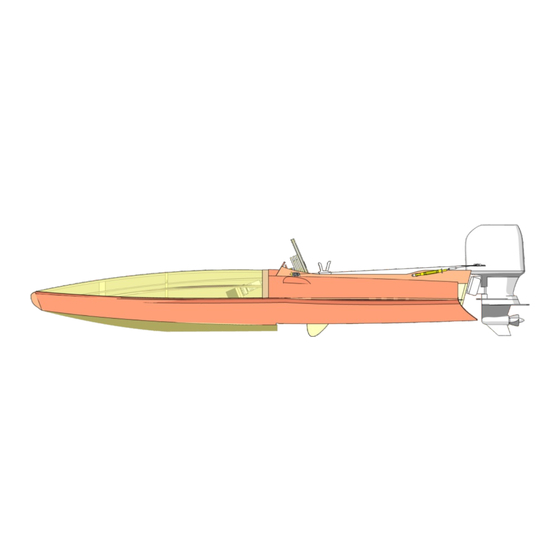
Aqua Race 60 outboard motor
without electric motor and propeller
28 mm Ø outrunner motor / 3.17 mm shaft / 3000 KV
Two-blade boat propeller, 29 - 31 mm Ø
actronic 40 speed controller
Prog-Card for actronic 40
2 x 2S 1800 mAh LiPo or 7 NiMH cells
6
6.1
0
5
2
Insert frames 1 to 4
in the slots in the
Depron jig 0. Insert
the keel 5 in the
notches in the
frames and the jig 0,
and glue the parts
together. Allow the
glue to set hard, then
glue the stringers 7
in place as shown.
6.1
Order No. 7005/01
Order No. 7002/51
Order No. 7002/49
5
5
7
Tip
Gluing the internal part 4.1 of frame 4 to the structure
produces a buoyancy chamber in the bow which
renders the boat unsinkable.
8
3
Fit the hull sides 8 in the notches of frames 1 to
4, aligning them with the step in frame 3 - as
shown in the detail view - before gluing them to
the stepped shoulder of parts 6.1. Glue the hull
sides 8 to the frames and the stringers 7.
We recommend our aero-pick modelling
pins, Order No. 7855/02, for holding
parts together during construction.
1
Glue together the bow components 6 and 6.1,
noting that they are handed, i.e. different left and
right. Glue these assemblies to either side of the
keel 5.
7
4
3
Order Number
3052/00
2
3
7
7
8
1
3
3
Advertisement
Table of Contents

Summary of Contents for Spitfire Aeronaut
- Page 1 Order Number 3052/00 Introduction: The model should be assembled following the sequence of the stages of construction described in these instructions. The laser-cut components are individually numbered. The manufacturing method leaves small tabs on some parts which have to be cut away using a thin-bladed modelling knife. The dark edges of the laser-cut parts should be rubbed off using abrasive paper in order to obtain sound glued joints.
- Page 2 Glue the aft bottom panel 9 to frames 1 to 3. Glue the half-frame 10 to the bottom panel 9, flush with frame 3 and the step in the hull sides 8. Glue the reinforcements 5.1 + 5.2 to both sides of the keel 5. Glue the forward bottom panel 11 to frame 10, aligning it with the step in the hull sides 8, then glue it...
- Page 3 Remove the support lugs from frames 1 to 4 and the keel 5. Glue the stringers 15 in place, followed by stringers 12, 13 and 14. Glue the reinforcements 24 to the keel 5. Glue the cockpit sides 16 and the cockpit front panel 17 in place.
- Page 4 Assemble the control stand, which supports the steering wheel and servo, from parts 18 to 23. Note that parts 18 1 mm and 19 must be at right-angles to each other. The brass bush 22 should project out of the instrument panel 23 by 1 mm.
- Page 5 Roughen the steering column over a length of 9 mm with abrasive paper, then assemble the steering wheel - consisting of parts 26 to 30 - using two-pack adhesive. Set the servo to centre, Turn the output arm Insert the servo / servo and fit the output arm on through 90°, and fix the plate assembly in the slot...
- Page 6 Open up the ring-screw 36, fit the return pulley 37 on it, then close the loop again. Glue the ring- screw in the pulley bracket 35. Screw the external fittings to the model as shown in this illustration, using screws and / or glue.
- Page 7 Place the two kneeling boards 42 in the cockpit, and screw them to parts 24. Glue the fabric support 45 on the stringers. Peel away the silicone backing paper from the underside of the fabric, and lay the adhesive-coated face on the hull.
- Page 8 The final stage is to install the receiver and speed controller. When you have checked everything one last time, you can safely take the boat to the water. Please be cautious when opening the throttle: sudden changes in throttle could cause the Spitfire to flip over.
- Page 9 No. Part Material Quantity Size Sheet Depron 300 x 600 Frame Plywood 3 mm Frame Plywood 3 mm Frame Plywood 3 mm Frame Plywood 3 mm Keel Plywood 2 mm Keel reinforcement Plywood 2 mm Keel reinforcement Plywood 2 mm Keel Mahogany plywood 1.5 mm...
- Page 10 With this CG position your “Spitfire” is set up to run efficiently when the water is calm and there is little wind. The boat “planes” on the last third of the hull, with the bow and midship sections out of the water.
- Page 11 Notes on the dummy driver In technical terms it is not essential to install a dummy driver in your “Spitfire”, but there is no doubt that the model looks a great deal better with a skipper on board, especially since onlookers have little idea of the boat's scale unless a driver figure is in the cockpit.
Need help?
Do you have a question about the Aeronaut and is the answer not in the manual?
Questions and answers