Table of Contents

Subscribe to Our Youtube Channel
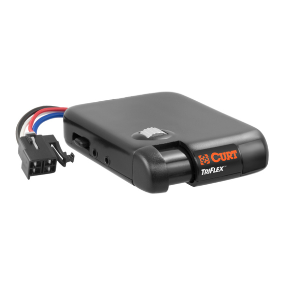
Summary of Contents for curt 51515
- Page 1 BRAKE CONTROL ADVANCED ELECTRONIC ACCELEROMETER TRAILER BRAKE CONTROL INSTALLATION AND USER GUIDE For use with 12 volt negative ground systems only For trailers with 2 – 8 brakes Read, follow and save this guide for future reference. 51140...
- Page 2 - Brake control connection harness supplied with the tow vehicle (if equip’d) - CURT quick plug – custom connector for specific vehicles. See catalog for availability - CURT part number 51515 or 51516 male quick plug with pigtails - CURT part number 51500 brake control wiring kit Important Information - CAUTION: Read and follow installation and setup instructions carefully.
- Page 3 using 10 gauge minimum stranded wire. Connecting to existing wiring or an alternate ground may damage vehicle circuits, lead to failure of the brake control module, loss of trailer brakes or vehicle fire. - NOTICE: Removal of the factory supplied quick plug can void warranty. Features - Digital display provides detailed brake force output and sensitivity position - Provides automatic and manual trailer braking...
- Page 4 Controls and Components 1. Digital display 2. Sensitivity adjustment 3. Output adjustment thumbwheel 4. Manual control lever 5. Quick plug connector 6. Switch for manual control max output, 100% or output setting 7. Switch manual control stoplight activation 8. Mounting bracket...
-
Page 5: Sensitivity Control
Controls and Display Output Control The output control thumbwheel establishes the maximum amount of power available to the trailer brakes when braking. The only exception would be when the manual control is setup for 100% braking, see "Set manual control out- put and brake light switches". -
Page 6: Manual Control
The sensitivity control setting is shown as through with being the least aggressive and being the most aggressive. The display flashes the setting for a few seconds after adjustment is complete. Manual Control The manual control is located on the front of the brake control unit at the left side. The manual control only applies trailer brakes. -
Page 7: Digital Display
Digital Display The digital display shows the output setting when the control is activated. It is used to setup and monitor the brake control and can be used when trouble shooting. Blank display, does not illuminate when Flashing, trailer disconnected, control is activated, check installation off after 60 seconds Blank display, standby mode,... -
Page 8: Installation
Installation Set Manual Control Output and Brake Light Switches There are two small switches located at the rear of the unit that can be ac- cessed by removing the rectangular cover. Once accessed, the switch positions can be changed using a small pointed tool. In the illustration above the switch on the right controls the level of output avail- able to the trailer brakes when using the manual control. - Page 9 Mounting 1. Determine a suitable mounting location. A) The unit must be mounted securely to a solid surface. B) The unit must be easily reached by the driver. C) The area behind mounting location must be clear so no damage will be done when drilling.
- Page 10 Check the owner’s manual for plug avail- ability, location and installation. If the mating plug supplied with the vehicle is no longer available, a CURT quick plug can be used (see CURT catalog for application information).
-
Page 11: Wiring Diagram
Wiring Diagram Feed two 10 gauge wires, one white and black, from the mounted brake control to the battery area. Using a ring terminal, connect the black wire to the "AUX" side of the 30 amp circuit breaker. Leave the white wire to be connected later. Using a 10/12 gauge butt connector, attach the black wire from the "AUX"... - Page 12 Run a 10 gauge blue wire from the tow vehicle’s trailer plug "brake" terminal to the brake control module. Using a 10/12 butt connector, connect this wire to the module’s blue wire NOTE: Stoplight switch connection on Ford vehicles including, Mercury Mountaineer.
- Page 13 Setup Once all electrical connections are complete and the single decimal point is seen, while parked on a level surface, plug the trailers electrical connector into the tow vehicle’s plug. Making the trailer connection initiates the mounting position calibration mode. C.C may be seen on the display followed by either .
-
Page 14: Helpful Tips
that is dry and level. At approximately 25 MPH, apply the tow vehicle brakes. If trailer braking is insufficient, adjust the output control to the right. If the trailer brakes lockup adjust the output control to the left. Repeat this step until stops are firm, just short of lockup. - Page 15 TROUBLESHOOTING GUIDE (TEST WITHOUT TRAILER FIRST): No trailer connected CONDITION DISPLAY PROBABLE CAUSE POSSIBLE SOLUTION Decimal point does not light Blank No power to control, no Check brake control ground, reversed black and wiring white wires Decimal point on after 12 – 15 Decimal Red wire connected to Check brake control...
- Page 16 With trailer connected CONDITION DISPLAY PROBABLE CAUSE POSSIBLE SOLUTION Display shows only 1 Decimal No connection between Confirm connection to trailer decimal point when power is brake control and trailer connector. Confirm connector applied to control. No trailer brakes – Blue wire circuit terminal positions.


Need help?
Do you have a question about the 51515 and is the answer not in the manual?
Questions and answers