Table of Contents

Summary of Contents for K-Sonic KS-72
- Page 1 ULTRASONIC SEWING MACHINE KS SERIES Operation Manual MODEL: KS-72 MODEL: KS-2010 KS-85 KS-3010 • Please read this manual carefully before use for an appropriate way of using this product • After reading, please keep this manual properly...
-
Page 2: Table Of Contents
Table of Contents Chapter 1 Introduction ................2 Chapter 2 Specifications ..............4 Chapter 3 Description of Warning Symbols..........5 Chapter 4 Safety Precautions ...............6 Chapter 5 Description of Delivery and Installation ........7 Chapter 6 System Function and Specification 6.1 Out-look Dimensions ..............8 6.2 Structural Diagram and Description of Each Part ......10 6.3 Pneumatic Circuit Diagram ............ -
Page 3: Chapter 1 Introduction
Chapter 1 Introduction 1.1 Operating Principle: In KS-Series Ultrasonic Lace Sewing Machine (Ultrasonic Sealing Machine), there is an Ultrasonic Generator which converts the power source (115V or 230VAC, 50/60Hz) into high voltages and frequencies of Ultrasonic energy, which is then fed into a transducer;... - Page 4 1.4 The machine complies with the requirements of the following relevant EU directives: Machinery Directive 98/37/EC amend by 2006/42/EC, Low Voltage Directive 73/23/EEC amend by 2006/95/EC, and Electromagnetic Compatibility Directive 89/336/EEC amend by 2004/108/EC, and is also meet the following standards: EN ISO 12100-1 EN ISO 12100-2 EN 60204-1...
-
Page 5: Chapter 2 Specifications
Chapter 2 Specifications Model KS-72 KS-85 KS-2010 KS-3010 Power 1400W 900W Rating Ultrasonic 20 KHz 30 KHz Frequency Power AC230V, 10A, 50/60Hz, single phase supply Air Source 6 Kg/cm² Control Auto Frequency Tracking Over Load Overload Indicating Lamp On, Ultrasonic Stop... -
Page 6: Chapter 3 Description Of Warning Symbols
Chapter 3 Description of Warning Symbols Symbol Description Warning Hazardous voltages cause severe injury or death. Disconnect all source of power before servicing. Caution(Lighting and Noise) 1. The machine should be operated under sufficient lighting. 2. During the operation, high-frequency sound will be generated. The operator should be sure to wear the ear protectors. -
Page 7: Chapter 4 Safety Precautions
Chapter 4 Safety Precautions 4.1 Please operate the machine according to the Operation Manual. Improper operation, installation or adjustment may cause malfunction or affect the normal function of the machine. If you experience any problems in the operation, please contact the sales department of the company or a local representative. 4.2 Please follow the instructions on the warning signs to avoid damage. -
Page 8: Chapter 5 Description Of Delivery And Installation
Chapter 5 Description of Delivery and Installation 5.1 Condition for mechanical operation Environment temperature 0~35℃. Environment humidity20%~85%RH. Maintain ventilation and airflow. Avoid operating around heavy contaminants or dusts. Avoid exposure to direct sunlight. 5.2 Condition for transportation A forklift can be used to transport the machine. Be sure to place the machine on a pallet before being transported by the forklift. -
Page 9: Chapter 6 System Function And Specification
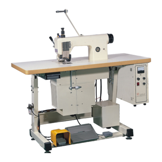
Chapter 6 System Function and Specification 6.1 Out-look Dimensions A. KS-72 AMPLITUDE ULTRASONIC LACE SEWING MACHINE KING ULTRASONIC CO.,LTD B. KS-85 AMPLITUDE ULTRASONIC LACE SEWING MACHINE KING ULTRASONIC CO.,LTD... - Page 10 C. KS-2010, KS-3010 焊頭轉速調整 花輪轉速調整 功率調整 振幅表 連續/腳踏開關 過載指示燈 電源指示燈 ULTRASONIC LACE SEWING MACHINE KING ULTRASONIC CO.,LTD...
-
Page 11: Structural Diagram And Description Of Each Part
6.2 Structural Diagram and Description of Each Part A. KS-72, KS-85 (Main M/C) AMPLITUDE ULTRASONIC LACE SEWING MACHINE KING ULTRASONIC CO.,LTD... - Page 14 Item Parts Name Function Description Generator Converts power source into ultrasonic energy. Working Table Provide a workbench. Load the transmission gear, cylinder and rollers Machine Head etc. The meter indicates the air pressure of the roller Air Pressure Meter and horn which is applied to the work piece. It is for adjusting the pressure of air system.
- Page 15 The working roller is made of special hardened steel material, and should be handled with care Working Roller as not to damage the surface. When this roller is changed or replaced, the axis of roller must be exactly paralleled with the horn surface to perform good and uniform operation.
- Page 16 Belt Tension Bar Adjust tension of the timing belt. Lower Transmit Shaft Link timing pulley to drive lower feed roller. Conductive Brass Ring A Brass ring for electric conduction. A component of transmission mechanisms which Timing Pulley conveys the lower motor’s power to tooling horn. These bolts adjust the height and horizontal plane of the horn surface.
- Page 17 The mechanism supporting the upper puller roller. Puller Roller Frame It can lift up upper puller roller when working on shaped pieces. Pushing away from operator, the puller roller will Puller Roller Lever be lifted up. Pulling towards the operator, it will be lowered down.
- Page 18 electrical contact. Warning: Do not touch the carbon brushes except by authorized technician. Transmission of electrical power from the power Power Supply Cord source to the transformer unit. Transmission of control circuit signals Cable with 10P Connector Transmission of high-voltage ultrasonic energy to Cable with 2P Connector the oscillator unit.
- Page 19 B. KS-72, KS-85 (Generator) FUSE FUSE AMPLITUDE 2 PIN ULTRASONIC LACE SEWING MACHINE KING ULTRASONIC CO.,LTD 10 PIN Item Parts Name Function Description The meter indicating both the vibration amplitude and the output power. When loading, the needle will raise a little higher.
- Page 20 on front side of the generator. Function Switch Selecting the operation way by auto or foot sw. (CONT./ FOOT SW.) The knob for adjusting the feeding speed of sealing roller and puller roller. It should be Roller Speed Adjusting adjusted to match the feeding speed of tool horn. Knob (SPEED A) The feeding speed will be increased as the knob is rotated clockwise.
- Page 21 C. KS-2010, KS-3010 (Main M/C) 焊頭轉速調整 花輪轉速調整 功率調整 振幅表 連續/腳踏開關 過載指示燈 電源指示燈 ULTRASONIC LACE SEWING MACHINE KING ULTRASONIC CO.,LTD...
- Page 24 Item Parts Name Function Description Generator Converts power source into ultrasonic energy. Working Table Provide a workbench. To raise up the machine head’s height to increase Spacer the convenience of pulling the fabric. Load the transmission gear, cylinder and rollers Machine Head etc.
- Page 25 Front Cover To support and fix the puller roller frame. To support and fix working roller, as well as to Roller Bracket adjust the axis of roller parallel with the horn surface. The working roller is made of special hardened steel material, and should be handled with care Working Roller as not to damage the surface.
- Page 26 A component of transmission mechanisms which Timing Pulley conveys the lower motor’s power to tooling horn. Drives the working roller and puller roller by a AC Motor linking mechanism. A component of transmission mechanisms which Timing Pulley conveys the upper motor’s power to working roller.
- Page 27 Transmission of electrical power from the power Power Supply Cord source to the transformer unit. Transmission of electrical power from the Cable with 2P Connector generator to the control unit. Transmission of control circuit signals. Cable with 10P Connector Transmission of high-voltage ultrasonic energy to Cable with 2P Connector the oscillator unit.
- Page 28 D. KS-2010, KS-3010 (Generator & Control Unit) 焊頭轉速調整 花輪轉速調整 功率調整 振幅表 連續/腳踏開關 過載指示燈 電源指示燈 FUSE FUSE 2 PIN 2 PIN ULTRASONIC LACE SEWING MACHINE KING ULTRASONIC CO.,LTD 10 PIN Item Parts Name Function Description The knob for adjusting the speed of tool horn. The speed setting used depends on the materials, pattern of roller, pressure of roller and the power Horn Speed Adjusting...
- Page 29 The meter indicating both the vibration amplitude and the output power. When loading, the needle will raise a little higher. Ampere Meter Caution: If the needle in the meter indicates over 1.5A, the ultrasonic system must has some defect, please stop working and check. Select Switch Selecting the operation way by auto or foot sw.
-
Page 30: Pneumatic Circuit Diagram
6.3 Pneumatic Circuit Diagram A. KS-72 / KS-2010 / KS-3010 Speed Adjusting Cylinder Controller Solenoid Valve Muffler Muffler Pressure Regulator Pressure Speed Air Filter Gauge Adjusting Controller Source Speed Adjusting Cylinder Controller KS-85 Solenoid Valve (Foot Switch) Muffler Muffler Pressure... -
Page 31: Wiring Diagram
6.4 Wiring Diagram A. MAIN WIRING DIAGRAM A-1 (KS-72) - Page 32 A-2 (KS-85)
- Page 33 A-3 (KS-2010, KS-3010)
- Page 34 B. GENERATOR WIRING DIAGRAM (KS-72, KS-85, KS-2010, KS-3010)
-
Page 35: Circuit Diagram
6.5 Circuit Diagram A. MOTOR SPEED CONTROL CIRCUIT DIAGRAM A-1 (KS-72 UPPER MOTOR: WORKING ROLLER) - Page 36 A-2 (KS-72 LOWER MOTOR: TOOLING HORN)
- Page 37 A-3 (KS-85, KS-2010, KS-3010)
- Page 38 B. GENERATOR CIRCUIT DIAGRAM (KS-72, KS-85, KS-2010, KS-3010)
-
Page 39: Chapter 7 Description Of Operation
Chapter 7 Description of Operation 7.1 Block Diagram of Machine System PAPERS FEDING SYSTEM ULTRASONIC GENARATION SYSTEM POWER SOURCE DYNAMIC CONTROL DRIVING SYSTEM SYSTEM SUPPORTER MECHANISM... -
Page 40: Notices Of Operation
7.2 Notices of Operation A. Regular HORN inspection 1. If there are wear marks on the surfaces of HORN, which lead to bad processing, it should be disassembled and surfaces grinded. ※ A newly manufactured HORN provided by our company can be grinded for another 0.4mm on the surfaces. - Page 41 5. Thickness of the working material: With same raw materials, higher pressures are needed for thicker materials. 6. Processing speed: High pressure for high speed ※ If quality items are to be processed, the operator needs to review factors leading to bad processing. Do not try to solve the problem by increasing the roller pressure.
-
Page 42: Installation And Working Preparation
7.3 Installation and Working Preparation A. Adjust the adjustable stand to get a suitable working height, if it is necessary. B. Installation of paper and O.P.P. tape: Take the paper tape, O.P.P. tape and the supporter from the accessory box. And take the small accessory parts from the tools drawer attached below the Table mechanisms, and then thread the paper strip and O.P.P. -
Page 43: Installation And Replace The Tape Strip Holder
7.4 Installation and Replace the Tape Strip Holder A. Lift up the puller roller and working roller. B. Follow the Illustration to assembly or disassembly the different width tape strip holder, guider and tapes. (STEP 1) (STEP 2) (STEP 3) (STEP 4) - Page 44 C. To install the paper tape and O.P.P. tape into the tension mechanism and guide, let the paper and O.P.P. be under the working roller and the puller roller. (at this time, the working roller and horn are separated and the upper and lower puller roller are separated too) D.
-
Page 45: Installation And Replace The Working Roller
(loosen the screws)and raise or lower the outer bracket to suit (retighten the screws) the retest. (KS-72, KS-85 Fig. 1) (KS-72, KS-85 Fig. 2) (KS-2010, KS-3010 Fig. 1) -
Page 46: Replacement Of The Tooling Horn
7.6 Replacement of the Tooling Horn The horn surface will be scratched by the roller due to long or wrong speed adjustment. In this case, the machine can not cut and seal the cloth correctly. The tooling horn should be repaired or changed using the following procedures and drawings: A. - Page 47 E. Fit a new horn, or repair the horn by grinding the horn surface until a smooth surface is achieved, then replace it. Caution: The horn may only be grind 2 or 3 times. F. After changing the tooling horn, the horn surface should be checked to see whether it is paralleled to the table surface or not.
-
Page 48: How To Operation
7.7 How to Operation A. Continuous Working: 1. Set on the power source by pushing the line switch on the front side of the generator. 2. Lift up the puller roller by pushing down the lever POSITION 1: Lift up the puller roller to insert the workpiece. POSITION 2: Descend the puller roller to press the workpiece and lower puller roller for running. - Page 49 5. Insert the workpiece in between the paper strip and O.P.P. strip. 6. Place down the working roller and puller roller by tread down the left side foot switch. 7. Tread down the treadle switch and the puller rollers will move the work-piece and strips of paper between working roller and horn.
- Page 50 1. Output adjustment The output adjustment is located on the front panel of generator. The output knob is usually set at scale 8, if the work-piece melts excessively (and it is difficult to reduce the roller pressure and speed), then rotate the knob counter clockwise and reduce the power output.
-
Page 51: Chapter 8 Troubleshooting
Chapter 8 Trouble Shooting Please follow the list as below for check up. In case of a failure that is impossible to avoid, please contact your local authorized representative service center for inspection and maintenance. Symptom Causes of Failure Solution Check if the power supply Connect the power plug and the cord has been properly... - Page 52 Check if the tooling horn Replace the tooling horn cracked Check if AC cooling fans Replace the cooling fan Overload lamp light does not work cause of the tooling horn temperature too high Check if 10 pin control cable Properly insert the terminal of 10 The working roller disconnected pin control cable into 10P control...
-
Page 53: Chapter 9 Maintenance
Chapter 9 Maintenance It is recommended to perform maintenance at least once a week. While performing maintenance and cleaning the works, please turn off the power. 1. Please wipe the machine clean when finished. 2. Purge accumulated water in the filter. 3. - Page 54 Manufacturer : King Ultrasonic Co., Ltd. No.8, Wugong 5 Rd, Xinzhuang Dist., New Taipei City 24890, Taiwan (R.O.C.) Tel : 886-2-22980299 Fax : 886-2-22980399 2011 02 Rev.A1...
Need help?
Do you have a question about the KS-72 and is the answer not in the manual?
Questions and answers