
Summary of Contents for EDU-TOYS CIRCUIT MAKER Skill Builder 125
- Page 1 Copyright © 2014 by Elenco Electronics, Inc. All rights reserved. No part of this book shall be reproduced by 753095 ® any means; electronic, photocopying, or otherwise without written permission from the publisher.
- Page 2 Table of Contents Basic Troubleshooting Advanced Troubleshooting Parts List Project Listings 9, 10 How to Use Circuit Maker Skill Builder 125 Projects 1 - 125 11-60 About Your Circuit Maker Skill Builder 125 Parts 4, 5 Other Circuit Maker Products...
- Page 3 Parts List (Colors and styles may vary) Symbols and Numbers Important: If any parts are missing or damaged in shipping, DO NOT RETURN TO Target. Call toll-free (800) 533-2441 or e-mail to help@elenco.com. Customer Service ● 150 Carpenter Ave. ● Wheeling, IL 60090 U.S.A. Qty.
-
Page 4: How To Use Circuit Maker Skill Builder
How to Use Circuit Maker Skill Builder 125 Circuit Maker Skill Builder 125 uses building You need a power source to build each circuit. Usually when the motor is used, the glow blocks with snaps to build the different This is labeled and requires two (2) 1.5V... - Page 5 About Your Circuit Maker Skill Builder 125 Parts (Part designs are subject to change without BATTERY HOLDER RESISTORS notice). Resistors “resist” the flow of electricity and are The batteries (B1) produce an electrical voltage BASE GRID used to control or limit the current in a circuit.
- Page 6 About Your Circuit Maker Skill Builder 125 Parts SPEAKER INTEGRATED CIRCUITS (ICs) MOTOR The speaker (SP) converts electricity into Some types of electronic components can be The motor (M1) converts electricity into sound by making mech- super-miniaturized, allowing many thousands of mechanical motion.
- Page 7 Introduction to Electricity What is electricity? Nobody really knows. We only know how to produce it, There are two ways of arranging parts in a circuit, in series or understand its properties, and how to control it. Electricity is the movement of in parallel.
- Page 8 DOs and DON’Ts of Building Circuits After building the circuits given in this booklet, you may wish to experiment on Examples of SHORT CIRCUITS - NEVER DO THESE!!! your own. Use the projects in this booklet as a guide, as many important design concepts are introduced throughout them.
- Page 9 Advanced Troubleshooting (Adult supervision recommended) Slide switch (S1) and Press switch Space war IC (U3) and photoresistor ELENCO is not responsible for parts ® (S2): Build Project #1, if the lamp (L1) (RP): Build Project #4, both switches damaged due to incorrect wiring. doesn’t light then the slide switch is (S1 and S2) should change the sound.
-
Page 10: Table Of Contents
Project Listings Project # Description Page # Page # Project # Description Page # Project # Description Turn on the Light Laser Blaster Motor Magic Up, Up, and Away! Mind Reader Game Spin & Shoot Super Circuit Don’t Make a Sound Spin Out Siren Space War Discover the Diode... - Page 11 Project Listings Project # Description Page # Page # Page # Project # Description Project # Description Singing Motor Electron Warehouse Lagging Light Visual Volume Light Makes Light Sonic Flasher Daylight Alarm Go & Glow Stay or Blink Bang-Bang Bright Spin &...
-
Page 12: Turn On The Light
Project #1 Turn on the Light Circuit Maker Skill Builder 125 uses electronic blocks that snap onto a clear plastic grid to build different circuits. These blocks have different colors and numbers on them so that you can easily identify them. -
Page 13: Super Circuit
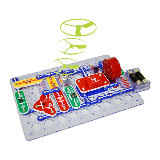
Fan may not rise until switch is released. Numbers Circuit Maker Skill Builder 125 uses electronic Place the glow fan on the motor (M1). If the fan doesn’t fly off, then push and release blocks that snap onto a clear plastic grid to the press switch several times rapidly when it is Turn on the slide switch (S1). -
Page 14: Space War
Project #4 Space War Build the circuit shown on the left, which uses the space war integrated circuit. Activate it by flipping the slide switch (S1) or pressing the press switch (S2), do both several times and in combination. You will hear an exciting range of sounds, as if a space war is raging! The space war IC (U3) is a super-miniaturized electronic circuit that can play a variety of cool sounds stored in it by using just a few extra... -
Page 15: Stick Around Saucer
Project #7 Stick Around Saucer Build the circuit shown on the left which is the same as the circuit in Project #2 but with the motor part reversed. Place the glow fan on the motor. Turn on the slide switch (S1), wait for the motor to reach full speed, then turn off the switch. -
Page 16: Spin & Dim
Project #9 Spin & Dim Build the circuit shown on the left. The parts are arranged When you turn on the slide switch (S1), the fan will spin and the lamp as a series circuit. You (L1) should turn on. The fan will take a while to start turning due to can swap the locations inertia. -
Page 17: The Diode Dude
Project #11 The Diode Dude Build the circuit shown on the left. When you turn on the slide switch (S1), current flows from the batteries (B1) through the switch, through the 100W resistor (R1), through the LED (D1, light emitting diode) and back to the battery. The turned on switch completes the circuit. -
Page 18: Clippy The Conductor
Project #13 Clippy the Conductor Rebuild the circuit from Project #11 but leave the slide switch (S1) out as shown on the left. When you place a paper clip across the terminals as shown in the picture on the left, current flows from the batteries (B1) through the 100W resistor (R1), through the LED (D1), and back to the battery. -
Page 19: Mumbling Motor
Project #15 Mumbling Motor Place the fan on the motor (M1). Press the press switch (S2) and listen to the motor. Why does the motor make sound? If you replace the motor with the 2.5V lamp (L1), then it will work the same as the “Hear the Motor”... -
Page 20: Hi-Low Fan
Project #17 Hi-Low Fan Build the circuit shown on the left. When you close the slide switch (S1), current flows from the batteries WARNING: through the slide switch (S1), motor (M1), the lamp (L1), and back to Moving parts. Do not the battery (B1). -
Page 21: Magical Music
Project #19 Magical Music Build the circuit shown on the left. When you turn on the slide switch (S1), the music integrated circuit (U1) may start playing one song then stop. Each time you press the press switch “doorbell button” (S2) the song will play again and stop. -
Page 22: Simple Siren
Project #21 Simple Siren Build the circuit shown on the left. When you turn on the slide switch (S1), the integrated circuit (U2) should start sounding a very loud alarm sound. This integrated circuit is designed to sweep through all the frequencies so even hard of hearing people can be warned by the alarm. - Page 23 Project #23 Mind Reader Game Build the circuit below. It uses a paper clip and The object is for Player 2 to guess the location 3-snap shorting bar and slide the switch off and a 3-Snap Wire as “shorting bars”. by placing one end of the paper clip on the 5- on to reset the sound.
- Page 24 Project #24 Don’t Make a Sound Use the circuit from Project #23, but now place a 3-snap wire and the LED (D1) as “shorting bars” under the paper sheet as shown on left. Setup: Player 1 sets the “Quiet Zone” by placing the 3-snap wire and the LED (D1) under the paper on columns 2, 3 or 4, leaving only one open.
- Page 25 Project #26 Shine On Siren Build the circuit shown on the left. Cover the photoresistor (RP) and turn on the switch (S1). A police siren is heard for a while and stops, then you can control it by covering or uncovering the photoresistor.
- Page 26 Project #31 Project #32 Transistor Control Slow & Bright Place the fan on the motor (M1) Compare this circuit to Project and turn on the slide switch (S1) #31. It works the same way, but - nothing happens. Push the the lamp is brighter here and the press switch (S2), the lamp motor is slower.
- Page 27 Project #35 Mixed Up Music In the circuit, the outputs from the alarm and music ICs are connected together. Build the circuit shown and then place the alarm IC (U2) directly over the music IC (U1), resting on two 1-snaps and a 2-snap. Turn on the switch (S1) and you will hear a siren and music together while the lamp (L1) varies in brightness.
- Page 28 Project #39 Space Battle Project #40 Bizarre Blinker Build the circuit shown on the left. Turn on the switch (S1) and you will hear exciting sounds, as if a space battle is The preceding circuit is loud and raging! may bother people around you, so The motor (M1) is used here replace the speaker (SP) with the as a 3-snap wire, and will not...
-
Page 29: Motor Magic
Project #43 Motor Magic This circuit is controlled by spinning the motor (M1) with your hands. Turn on the switch. A police siren is heard and then stops. Spin the motor and it will play again. Note, however, that music can be heard faintly in the background of the siren. -
Page 30: Wave & Watch
Project #48 Wave & Watch This circuit does not use the noisy speaker (SP) but instead uses a nice quiet LED (D1). Turn on the slide switch (S1), the LED flickers. Wait a few seconds, and then cover the photoresistor (RP), and the flicker stops. -
Page 31: Lingering Light
Project #50 Lingering Light Build the circuit and press the switch (S2). You see that the LED (D1) turns off slowly after you release the switch. This delay in turning off the LED is caused by the 470mF capacitor (C5). Capacitors can store electricity and are used to delay changes in voltage. -
Page 32: Auto-Off Night Light
Project #53 Auto-Off Night Light Build the circuit to the left. When you turn on the slide switch (S1) the first time the LED (D1) will come on and very slowly get dimmer and dimmer. If you turn the slide switch (S1) off and back on after the LED goes out it will NOT come on again. -
Page 33: Reflection Detector
Project #55 Reflection Detector Build the circuit to the left. Place it where there won’t be any room light hitting the photoresistor (RP) (such as in a dark room or under a table), and then turn it on. The 2.5V lamp (L1) will be bright, but there should be no sound. -
Page 34: Laser Flasher
Project #57 Laser Flasher When you press the press switch (S2), the integrated circuit should start sounding a very loud laser gun sound. The red LED will flash simulating a burst of laser light. You can shoot long repeating laser burst, or short zaps by tapping the press switch. -
Page 35: Spinning Rings
Project #59 Spinning Rings Setup: Cut out the disc on page #62 that looks like the one shown here. Using Scotch tape, attach the disc with the printed side up on the top of the fan blade. Place the blade on the motor as shown to the left and below. -
Page 36: Race Game
Project #61 Race Game Modify Project #59 by adding the pointer as shown on the left. The paper should be cut from page #62 and taped high enough on the speaker so the pointer will stick over the fan with paper. Bend the pointer at a right angle as shown on the left. Setup: Cut out the grid with four (4) colors from page #62 and place it under the base as shown on the left. -
Page 37: Spin Draw
Project #63 Spin Draw Rebuild the simple motor connection as shown on the left. This is the same setup as Project #59. Setup: Cut out a circular piece of thin cardboard from the back of an old spiral notebook or note pad. -
Page 38: Visual Volume
Project #65 Visual Volume Build the circuit shown on the left. Turn on the slide switch (S1), a police siren is heard. The loudness of the sound depends on how much light reaches the photoresistor (RP). Try partially shielding it or placing near a very bright light, and compare the sound. -
Page 39: Pop On, Pop Off
Project #70 Pop On, Pop Off Turn the slide switch (S1) on and off several times. You hear static from the speaker (SP) when you turn off the switch. The speaker uses electromagnetism to create changes in air pressure, which your ears feel and interpret as sound. -
Page 40: Little To Big
Project #73 Little to Big Place the fan on the motor (M1) and turn on the slide switch (S1), then compare this circuit to Project #31. Push the press switch (S2), the lamp doesn’t light now but the motor still spins. The lamp is dark because the 100W resistor (R1) limits the current through it. -
Page 41: Switch & Store
Project #76 Switch & Store Turn on the slide switch (S1) and the LED (D1) lights; it will not be very bright so turn off the room lights or hold your fingers around it to see it better. Push the press switch (S2) several times slowly;... -
Page 42: Alien Alarm
Project #78 Alien Alarm Build the circuit shown on the left and turn on the slide switch (S1). Press and hold the press switch (S2) to make the lamp (L1) brighter. Project #79 Same or “NOT” Build the circuit shown. Notice that when the press switch (S2) is pressed, the LED (D1) goes off. -
Page 43: This Or That
Project #80 This OR That Build the circuit shown. Notice that if you turn on the slide switch (S1) OR press the press switch (S2) the LED (D1) lights up. There is no partially lit state here, the diode is either totally on or totally off. While this may seem very simple and boring, it represents an important concept in electronics. -
Page 44: Neither This Nor That
Project #82 Neither This NOR That Build the circuit at left and test the combinations of the slide switch (S1) and press switch (S2). If you compare it to the OR circuit in Project #80, you can see the LED (D1) lights in the opposite combinations of that circuit. -
Page 45: Two-Way Light Switch
Project #84 Two-way Light Switch Build the circuit on the left. Note that two of the 2-snaps are left unconnected on one end because they will be used as switches in this project. If you connect the free ends of each of these 2-snaps both to the “high bar”... -
Page 46: Light Makes Light
Project #86 Light Makes Light Build the circuit to the left. Cover the photoresistor, turn the switch on, and notice that the LED is on for several seconds and then goes off. Uncover the photoresistor and place the unit near a light and the LED will light. -
Page 47: Flashing Flare
Project #89 Project #90 Flashing Flare Touch & Go Build the circuit Wet your fingers with some shown on the left. water or saliva and touch them The circuit uses across points A and B several Alarm times to hear some space war Space War ICs to sounds. -
Page 48: Fan Flash Energy
Project #92 Fan Flash Energy Place the fan on the motor (M1). Hold down the press switch (S2) for a few seconds and then watch the LED (D1) as you release the switch. The LED flashes briefly but only after the batteries (B1) are disconnected from the circuit. -
Page 49: Fun With The Alarm Ic
Project #95 Fun with the Alarm IC Place the fan on the motor (M1) and turn on the slide switch (S1). The lamp (L1) lights, the motor spins, and you hear a machine gun sound (with very faint music in background). Thoroughly cover the photoresistor (RP) with your hand and the sound becomes a siren. -
Page 50: Music Alarm Combo
Project #98 Music Alarm Combo Build the circuit shown and then place the alarm IC (U2) directly over the music IC (U1), resting on the three 1-snaps. Turn on the slide switch (S1) and you will hear a siren and music together. After a few seconds, covering the photoresistor (RP) will stop the music (but the siren continues). -
Page 51: Sing & Fling
Project #101 Sing & Fling In the circuit, the outputs from the alarm and music ICs are connected together. Build the circuit shown and then place the alarm IC (U2) directly over the music IC (U1), resting on two 1-snaps and a 2-snap. Turn on the slide switch (S1) and you will hear a siren and music together while the lamp (L1) varies in brightness. -
Page 52: Long Gone Light
Project #103 Long Gone Light Push the press switch (S2). If the fan is off the motor (M1) (or flies off) then the LED (D1) will be bright. It takes a lot of current to spin the motor when the fan is on it, and the voltage drops because the batteries (B1) cannot supply enough. -
Page 53: The Dark Dimmer
Project #105 The Dark Dimmer Turn on the slide switch (S1) and push the press switch (S2). If there is light on the photoresistor (RP), then the LED (D1) will stay on for a long time after you release the press switch. The energy stored in the 470mF capacitor (C5) keeps the controlling current to the NPN transistor (Q2) on even though the press switch was turned off. -
Page 54: Sonic Flasher
Project #107 Sonic Flasher Set the slide switch (S1) on, a space war sound plays and the LED (D1) flashes. Cover the photoresistor (RP) and press the press switch (S2) to change the sound. See how many sounds are programmed into the space war sound IC (U3). -
Page 55: Glow & Go
Project #109 Glow & Go Build the circuit to the left. Turn on the slide switch (S1). The alarm will sound, as long as light is present. Slowly cover the photoresistor (RP), and the volume goes down. If you turn off the lights, the alarm will stop. The amount of light changes the resistance of the photoresistor (less light means more resistance). -
Page 56: Light The Motor
Project #111 Light the Motor This circuit combines Projects #1, #2, and #10 into one circuit. Build the circuit and place the fan on the motor (M1). Depending on which of the switches (S1 and S2) are on, you can turn on either the lamp (L1) (Project #1), the motor (M1) (Project #2), or both together (Project #10). -
Page 57: Morse Code
Project #114 Morse Code This simple circuit can be used for communication. Press the press switch (S2) friends far away at night. During World War II Navy ships sometimes in long and short bursts to make a pattern of light flashes representing the dots communicated by flashing Morse Code messages between ships using and dashes shown in the Morse Code table below. -
Page 58: Touch Of Light
Project #117 Touch of Light Build the circuit on the left. You’re probably wondering how it can work, since one of the points on the NPN transistor (Q2) is unconnected. It can’t, but there is another component that isn’t shown. That component is you. -
Page 59: Electricity You Can Wear
Project #119 Electricity You Can Wear Did you ever wonder why clothes cling Snappy says: clothes together when they come out of the dryer? Did cling together you ever hear a crackling sound when you take because electricity is off a sweater? (If the room is dark you might all around us. -
Page 60: Bending Water
Project #121 Bending Water You need a comb (or plastic ruler) and a water Static electricity faucet for this project. Run the comb through discovered more than 2,500 your hair several times then hold it next to a years ago when the Greek slow, thin stream of water from a faucet. -
Page 61: Sunrise Light
Project #123 Sunrise Light Cover the photoresistor (RP) and turn on the slide switch (S1). The LED (D1) is off, but if you wait a long time then it will eventually light up. Uncover the photoresistor and the LED will light up in just a few seconds. - Page 62 FROM THE CIRCUIT MAKER FAMILY OF PRODUCTS: Circuit Maker Basic 40 Circuit Maker Sound Plus 200 Model CM-40 Model CM-200 Build Build over unique over unique Contains over Contains over projects! projects! parts! parts! Sample projects Sample projects Light Fan All at Once Launcher Playback &...
- Page 63 Page 34 for Project #59 Page 35 for Project #61 -62-...
- Page 64 CM-125 Block Layout Important: If any parts are missing or damaged, DO NOT RETURN TO RETAILER. Call toll-free (800) 533-2441 or e-mail us at: help@elenco.com. Customer Service ● 150 Carpenter Ave. Wheeling, IL 60090 U.S.A. Note: A complete parts list is on page 2 in this manual.
Need help?
Do you have a question about the CIRCUIT MAKER Skill Builder 125 and is the answer not in the manual?
Questions and answers