Table of Contents
Advertisement
Advertisement
Table of Contents

Subscribe to Our Youtube Channel
Summary of Contents for Jammin Pro studiomix 10
- Page 1 USER'S MANUAL...
- Page 2 IMPORTANT SAFETY SYMBOLS NOTE: CAUTION RISK OF ELECTRIC SHOCK DO NOT OPEN The symbol is used to indicate that some hazardous live terminals are involved within this apparatus, even under the normal operating conditions, which may be sufficient to constitute the risk of electric shock or death. The symbol is used in the service documentation to indicate that specific component shall be replaced only by the component specified in that documentation for safety reasons.
- Page 3 · Object and Liquid Entry Power supply Objects do not fall into and liquids are not spilled into the inside of the apparatus StudioMix 10: 18 W Power consumption for safety. StudioMix 12: 23 W Mains voltage ·...
-
Page 4: Table Of Contents
TABLE OF CONTENTS EQ mono channels 80 Hz / 15 dB 2.5 kHz / 15 dB 1.INTRODUCTION...........2 High 12 kHz / 15 dB 1.1 General mixing console functions..............2 EQ stereo channels 1.2 The user’ s manual................3 80 Hz / 15 dB 2.5 kHz / 15 dB 1.3 Before you get started................3 High... -
Page 5: Introduction
1.INTRODUCTION 5.SPECIFICATIONS Congratulations! In purchasing the StudioMix 10 / StudioMix 12 series micing concole Mono inputs you have acquired a mixing console whose small size belies its versatility and audio performance. Microphone inputs Type XLR, electronically balanced, The StudioMix Series represents a milestone in the development of mixing console technology. With the ME discrete input circuit microphone preamps including phantom power as an option. -
Page 6: The User' S Manual
Unbalanced use of 1/4"T RS connector ▲ Signal distribution: Summing of signals to the aux sends for effects processing and monitor mix, strain relief clamp distribution to one or several recording tracks, power amp(s), control room and 2-track outputs. sleeve ground shield signal ▲... -
Page 7: Control Elements And Connectors
Please note that all unit must be properly grounded. For your own safety, you should never 4.INSTALLATION remove any ground connectors from electrical devices or power cables, or render them inoperative. 4.1 Mains connection AC POWER IN Please sure that only qualified people install and operate the mixing console. During installation and operation, the user must have sufficient electrical contact to earth, Connect the power supply to the 3-pin mains connector on the rear of the console. - Page 8 3.2 Live ound Each mono input channel offers a balanced microphone input via the XLR connector and also features switchable +48 V phantom power supply for condenser microphones. The StudioMix preamps CD player provide undistorted and noised-free gain as is typically known only from costly outboard preamps. keyboard TAPE Please mute your play back system before you active the phantom power supply to prevent...
-
Page 9: Stereo Channels
CD player TAPE In the StudioMIX 10/StudioMix 12, the FX send is routed directly to the built-in effects processor. To make sure that the effects processor receives an input signal, you should not turn this control all the way to the left (-∞... -
Page 10: Connector Carry Of The Main Section
Connect to the assembled power adaptor The stereo inputs of the StudioMix 10 and StudioMix 12 have an input sensitivity switch which selects between +4 dBu and -10 dBv At -10 dBV (home-recording level), the input is more sensitive (requires less level to drive it) than at +4 dBu (studio level). - Page 11 100 FIRST-CLASS EFFECTS mixer and which gear you own, you can connect the following equipment. The StudioMix 10 / StudioMix 12 features a built-in digital stereo effects processor. This effects processor offers a large number of standard effects such as Hall, Chorus, Flanger, Delay and various combination effects.
-
Page 12: Main Section
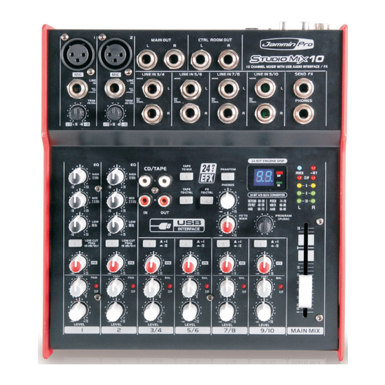
2.4 Main section LEVEL SETTING To correctly set the gains of the channels, first set the LEVEL controls of the input channels to their center positions (0 dB) Then use the TRIM controls to increase the input amplification until signal peaks show 0 dB +48 V POWER on the level meter.
Need help?
Do you have a question about the studiomix 10 and is the answer not in the manual?
Questions and answers