Advertisement
Table of Contents
- 1 Table of Contents
- 2 Quick Operation Guide
- 3 General Description
- 4 Control Panel Description
- 5 Menu Items
- 6 General Operation
- 7 Trigger Function Numbers
- 8 Multi-Device Control Rules
- 9 Auto-Dub from VTR
- 10 Multi-Point Loops
- 11 TBC Adjustment Control
- 12 Installation
- 13 GPI Inputs and Outputs
- 14 Dipswitch Functions and Connector Pinouts
- Download this manual
Advertisement
Table of Contents

Subscribe to Our Youtube Channel
Summary of Contents for Lance TDC-100
- Page 1 TDC-100 TD’S DISK CONTROLLER Installation and Operation Manual Software Version 3.4 September 2007 Lance Design / 27 Fairview Avenue / Ridgefield, Connecticut 06877 Tel: 203-894-8206 / Fax: 203-894-8207 www.lancedesign.com...
- Page 2 Lance Design, and also that the equipment is returned to Lance Design with prior authorization.
-
Page 3: Table Of Contents
Table of Contents Quick Operation Guide Page 4 General Description Page 7 Control Panel Description Page 7 Menu Items Page 9 General Operation Page 14 Trigger Function Numbers Page 15 Multi-Device Control Rules Page 17 Auto-dub From VTR Page 18 Multi-Point Loops Page 19 TBC Adjustment Control... -
Page 4: Quick Operation Guide
The display will say ‘CLR To Clear All!’. If you press the CLR key (while holding down the above three buttons) the TDC-100 will start clearing registers at the current register, and ascending until you either press the STOP button, or it reaches the last register (299). - Page 5 Quick Operation Guide - continued To recall an in or out time to the display, press FCN, then MARK IN or MARK OUT. The corresponding time value will be recalled to the display and the scratchpad register, so you can do arithmetic with it if desired (add and subtract). If you ‘double-click’...
- Page 6 This will cause the ASCII Pbus data to be displayed on line two of the panel. If the Pbus data is incorrectly formatted (invalid command) a ‘Pbus Format Error’ message will be displayed. Note that this menu item is turned off each time the TDC-100 is powered up.
-
Page 7: General Description
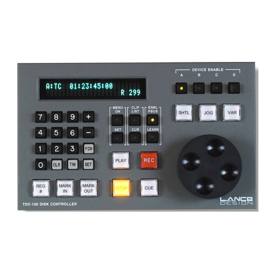
CONTROL PANEL DESCRIPTION The TDC-100 control panel provides the following controls (left to right on the panel): Numeric Keypad - for entry of numeric data, register numbers, timecodes, etc. - Page 8 REG# - used to select the active register from the 300 available registers. Press this key (it lights), and enter a 3-digit register number on the keypad. The active register number is displayed in the lower right corner of the display as ‘R 299’, for example.
-
Page 9: Menu Items
DEVICE ENABLE (A,B,C,D) - four device enable keys corresponding to the four control ports on the TDC-100. Any lighted key is enabled, and will be sent all transport commands and PBUS commands. If more than one is enabled, the one that is flashing is the currently-displayed one. - Page 10 CLIP LIST MODE (INT / EXT) This item selects the clip list mode that the TDC-100 uses to access the list of available clips on the ddr. The INT mode builds the list within the TDC-100, and will operate with any ddr which supports Odetics protocol. In this mode the list is limited to 99 clips.
- Page 11 CH C STATUS (CHECKED / IGNORED) CH D STATUS (CHECKED / IGNORED) These cause the TDC-100 to either check or ignore the status returned from the machine. If checked, the controller will make sure a machine is present before trying to cue it, and will wait until cued before rolling in play (if a cueup command has been issued).
- Page 12 If item is set to HIGH, they will rest low and will be pulled high when triggered. This item is generally set to LOW. SWITCHER TYPE (GVG / SONY) Selects type of production switcher TDC-100 is used with. Affects the trigger function numbers (swaps functions 0 and 1).
- Page 13 VIDEO FRAME RATE (25/30) Selects the video standard being used, in frames per second. For NTSC, 525/60 SDI, and any high-def formats that use 30 frames/sec, or 29.97 frames/sec set this item to ‘30’. For PAL, 625/25 SDI or other 25 frame/sec standards, select ‘25’. This setting must match the video frame rate being used in the ddrs.
-
Page 14: General Operation
GENERAL OPERATION WHAT IS A REGISTER? In this controller, a register refers one set of these items: Device A Inpoint Device A Outpoint Device A Clip Name (if enabled) Device B Inpoint Device B Outpoint Device B Clip Name (if enabled) Device C Inpoint Device C Outpoint Device C Clip Name (if enabled) -
Page 15: Trigger Function Numbers
When the switcher sends a TRIGGER, all enabled machines are sent a command corresponding to the ‘Function Number’ specified for that trigger in the switcher menu. The function numbers are as follows: When TDC-100 is in the GVG (Grass Valley) mode: Function Number Command... - Page 16 The SELECT BANK [0,1,2] triggers are new with version 3.0 software, and allow a single emem effect to recall up to three different playbacks per channel. If you have an effect in Emem 25 for example, register 025 will be recalled on the TDC when you recall that effect.
-
Page 17: Multi-Device Control Rules
MULTI - DEVICE CONTROL RULES This section describes how the controller handles various combinations of multiple machines and device enable numbers The controller front panel controls enabled machines; ones with lighted Device Enable buttons. Some front panel functions affect only the Displayed machine - the one whose letter is in the upper left corner of the display. -
Page 18: Auto-Dub From Vtr
Using Auto-Dub Feature to Transfer Material From VTR to Disk 1. Connect the vtr’s remote (9-pin) connector to one of the device control ports on the TDC-100. (e.g. Device Port D) 2. Connect the DDR that you want to record onto to another port (it’s probably already there. -
Page 19: Multi-Point Loops
Using Multipoint Loops Version 3.0 software has the capability to do multi-point loops, where for example you play a lead-in, loop an internal portion, then (upon receipt of a ‘exit loop’ trigger) play a tail out. Doing this requires four time values. Start Point --- Loop In --- Loop Out --- End Point The way the controller accomplishes this is to use a pair of registers. -
Page 20: Tbc Adjustment Control
TBC CONTROL WITH THE TDC-100 The TDC-100 can control VTR/Disk TBC or output video processor levels and timing. This is possible only for vtrs or disk recorders which allow these levels to be controlled via the standard RS-422 machine control port, via the standard Sony protocol. -
Page 21: Installation
INSTALLATION AND CONNECTIONS The TDC-100 consists of two pieces: the rack-mounted electronics frame (1RU) and the control panel. They are interconnected by the supplied 9-conductor cable, which provides data communications between the two, and power from the frame to the control panel. -
Page 22: Gpi Inputs And Outputs
GPI OUTPUT CONNECTIONS The GPI Output connections also appear on the 15-pin RS-232/GPI connector. These outputs are 74HC-series outputs. They may be used to drive CMOS or TTL- compatible 5-volt inputs only. They are not suitable for pulling down 24v, driving relays (other than low-power 5v relays), or other types of interface. - Page 23 All 9 pins (of the D-9) must be connected, and the maximum length using #22 conductors is 150’. If the panel must be extended beyond this length, it should be locally powered. Contact Lance Design for details. Device A,B, C, D Ports...
- Page 24 RS232/GPI DB-15 MALE DB-9 FEMALE PIN 1 SIGNAL GROUND PIN 5 PIN 2 DATA FROM PC TO TDC-100 PIN 3 PIN 3 DATA FROM TDC-100 TO PC PIN 2 Control Panel (Frame End) Control Panel (Control Panel End) Pin #...
Need help?
Do you have a question about the TDC-100 and is the answer not in the manual?
Questions and answers