Table of Contents
Advertisement
Quick Links
SERVICE MANUAL
SERVICE MANUAL
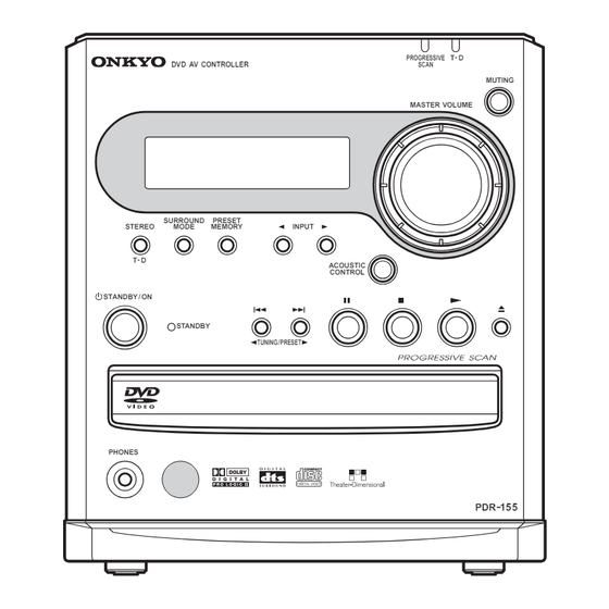
DVD AV CONTROLLER
PDR-155
MODEL
DV D AV CONTROLLER
SURROUND
PRESET
STEREO
MODE
MEMORY
INPUT
T - D
ACOUSTIC
CONTROL
STANDBY / ON
STANDBY
TUNING / PRESET
PHONES
Silver model
SUPP
230-240V AC, 50Hz
SUDT, SUDS
120V AC, 60Hz
SUGT, SUGQ
220-230V AC, 50/60Hz
SAFETY-RELATED COMPONENT
WARNING!!
THE MARK
FOUND ON SOME COMPONENT
PARTS INDICATES THE CRITICAL FOR RISK OF
FIRE AND ELECTRIC SHOCK.
WHEN REPLACING, BE SURE TO USE PARTS OF
IDENTICAL DESIGNATION.
MAKE LEAKAGE-CURRENT OR RESISTANCE
MEASUREMENTS TO DETERMINE THAT EXPOSED
PARTS ARE ACCEPTABLY INSULATED FROM THE
SUPPLY CIRCUIT BEFORE RETURNING THE
APPLIANCE TO THE CUSTOMER.
www.denom.com
T - D
PROGRESSIVE
SCAN
MUTING
MASTER VOLUME
MODE
ON
RECEIVER
TV/
TV/
TV/ SETUP
TV/ SETUP
SETUP
SETUP
ACOUSTIC
STANDBY
CONTROL
INPUT SELECTOR
SEARCH
LAST M
COND.M
FUNC.M
1
2
3
SP SETUP
SP SETUP
TEST T
TEST TONE
ONE
CH SEL
CH SEL
PROGRAM
AUDIO
ANGLE
SUBTITLE
4
5
6
DIST
DISTANCE
DISTANCE
DIST
ANCE
ANCE
UP
UP
UP
UP
CLEAR
LATE NIGHT
T-D/ ST
SURROUND
7
7
8
8
9
9
T- D SETUP
D SETUP
DO
DOWN
DO
DOWN
WN
WN
TIMER
RANDOM
+10
0
SHIFT
--/---
TOP MENU
OL +
OL +
MENU
TV VOL
TV V
TV V
TV VOL
TV
TV
TV
TV
TV
TV
TV
TV
PO
POWER
PO
POWER
WER
WER
INPUT
INPUT
INPUT
INPUT
TV CH -
TV CH -
TV CH +
+
TV CH
TV CH
TV CH
TV CH
TV CH
DVD
RETURN
SETUP
TV V
TV V
TV VOL
TV VOL
OL -
OL -
TV MUTING
TV MUTING
TV MUTING
REPEAT
A-B
STEP/ SLOW
TUNING
TUNER PRESET
MODE
MD / CDR / TAPE
SLEEP
DIMMER
DISPLAY
CLOCK
VOLUME
MUTING
PDR - 15 5
RC-506M
PDR-155
Ref. No. 3748
102002
Advertisement
Table of Contents

Related Manuals for Onkyo pdr-155


Summary of Contents for Onkyo pdr-155
- Page 1 PDR-155 Ref. No. 3748 102002 SERVICE MANUAL SERVICE MANUAL DVD AV CONTROLLER PDR-155 MODEL T - D PROGRESSIVE DV D AV CONTROLLER SCAN MUTING MASTER VOLUME MODE RECEIVER TV/ SETUP TV/ SETUP SETUP SETUP ACOUSTIC STANDBY CONTROL INPUT SELECTOR SEARCH LAST M COND.M...
- Page 2 PDR-155 SPECIFICATIONS-1 PDR-155 (DVD AV Controller) Input/Impedance Digital OPTICAL -21~ -15 dB Analog TV/LINE, MD/TAPE, CDR/VIDEO: RCA L/R (200 mV/50 k ) Nominal output/Impedance REC OUT (MD/TAPE, CDR/VIDEO): 200 mV/2.2 k MULTI CH OUTPUT (Front L/R, Surround L/R, Center, Subwoofer): 1 V/470...
- Page 3 PDR-155 SPECIFICATIONS-2 DVD SECTION Signal readout system: PAL/AUTO color television system Laser: Semiconductor laser, wavelength 650 nm (DVD)/780 nm (CD) Digital audio frequency response DVD linear audio: 48 kHz sampling 4 Hz - 22 kHz 96 kHz sampling 4 Hz - 44 kHz...
- Page 4 SWA-155/ D-M7/D-M5 SPECIFICATIONS-3 SWA-155X (subwoofer) INPUT: RCA L/R/C/SL/SR/ subwoofer (500 mV/47k ) AMPLIFIER SECTION Power Output (FTC) Front, Sound: 15 W x 5 (1kHz, 6 /EIAJ) Subwoofer: 25 W (100 Hz, 3 /EIAJ) Total harmonic distortion: 0.1% (Output: 5 W) Signal-to-noise ratio: 100dB (STEREO: IHF A0.5V input) SPEAKER SECTION Type: J'DRIVE system, 16 cm OMF cone...
- Page 5 PDR-155 SERVICE PROCEDURES-1 PROTECTION OF EYES FROM LASER BEAM DURING SERVICING This set employs a laser. Therefore, be sure to follow Laser Diode Properties carefully the instructions below when servicing. WARNING!! Wavelength: 780 nm SERVICE WARNING : DO NOT APPROACH THE Laser output: 0.14 mW...
-
Page 6: Pc Board
PDR-155 SERVICE PROCEDURES-2 INITIALIZING Factory-shipped condition Push button "ON" (Mechanical SW) Press the [STOP] and [STANDBY] same time. Push button "STANDBY". Remove the solder of Laser Diode shorting Connect Pickup and DVD main circuit PC board by FFC(3 pcs). Fix it with the DVD Mechanism Remove the solder of Laser Diode shorting on Pickup. - Page 7 PDR-155 EXPLODED VIEW CHASSIS F9501 F9001 P1001 (x16) P0011 A101 T9001 Z001 A111 www.denom.com...
-
Page 8: Pc Board
PDR-155 EXPLODED VIEW (LOADING MECHANISM) / PARTS LIST EXPLODED VIEW (LOADING MECHANISM) / PARTS LIST Z001 : DVD Mechanism DB-VLD304 GEM1036 GEM1036 To DVDM CN151 Lubricating Oil GYA1001 Lubricating Oil Lubricating Oil GYA1001 GYA1001 Parts list REF.NO REF.NO PART NO. - Page 9 PDR-155 EXPLODED VIEW / PARTS LIST TRAVERSE MECHANISM ASSY 17 (Torque : 0.12+/- 0.01 N m) 4 (Adjustment Screw) 4 (Adjustment Screw) (Torque : 0.12+/- 0.01 N m) 17 (Torque : 0.12+/- 0.01 N m) PARTS LIST Mark No. Description Part No.
- Page 10 PDR-155 BLOCK DIAGRAM NADG-7673 FUNCTION P C BOARD P3003 P3001 PART-1 BLOCK DIAGRAM MUTE PART-2 CONNECTION DIAGRAM TV/LINE MUTE PART-3 DISPLAY NADIS-7674 MULTI CHANNEL MUTE KEYs OUTPUT Q3001 MUTE SUB MICON BD3811K1 MUTE NAVD-7675 VIDEO OUTPUT Input Selector NAVD-7676 MD/TAPE...
-
Page 11: Pc Board
PDR-155 SCHEMATIC DIAGRAM : DSP CIRCUIT PC BOARD Q3003 to Tuner unit P1001A NADG-7673 79L07 -12V +12V Q3002 78L07 R8803 Q1101 R8801 QUAL RCLK R8802 RDATA X8801 4.332MHZ C8801 C8804 330J 2SC4617 C1101 VREF R1103 100/6.3 C3016 L8801 103K C8803... -
Page 12: Pc Board
SCHEMATIC DIAGRAM : DSP CIRCUIT PC BOARD to Tuner unit Q3003 P1001A 79L07 NADG-7673 -12V +12V Q3002 78L07 Q1101 2SC4617 C1101 R1103 C3016 103K 10/16 R1002 2.2K R1003 2.2K C1003 2.2/50 TREBLE BASS BAAS BOOST <MPP> only R3013 RS_VO R3007 470K LS_VO 2.2K... -
Page 13: Pc Board
PDR-155 R8803 R8801 QUAL RCLK R8802 RDATA X8801 C8801 4.332MHZ C8804 330J VREF 100/6.3 L8801 C8803 VDD1 VDD2 330J NCH-1477 VSS1 VSS2 VSS3 C8802 561J C8805 D8023 Q8023 104Z DTA124EE BAND MODE1 MODE2 MODE3 MARK R8176 R8177 R8179 R8180 R8102 C8806 100/6.3... -
Page 14: Table Of Contents
PDR-155 SCHEMATIC DIAGRAM : POWER TRANSFORMER : INLET TERMINAL PC BOARD : POWER SUPPLY PC BOARD PC BOARD NAPS-7677 NAPS-7678 NAPS-7678 NPT-1458 T9001 Q9502 1.24W C9001 SW12V PQ12RF1 103M Q9503 0.7W F9001 P9001 78M06 RL9001 P9007B P9007A R9501 SW6VVD Q9504... -
Page 15: Pc Board
SCHEMATIC DIAGRAM : POWER SUPPLY PC BOARD NAPS-7678 Q9502 1.24W SW12V PQ12RF1 Q9503 0.7W 78M06 R9501 SW6VVD Q9504 D9501 +11V +12V (1W) 78M12 21.0 RBV40 R9515 22 (1/2W) -11V -12V +12V R9516 22 (1/2W) +13V +5.6S CPUGND CPUGND DGND -12V DGND -21.3 Q9505... -
Page 16: Pc Board
PDR-155 : POWER TRANSFORMER : INLET TERMINAL PC BOARD PC BOARD NAPS-7677 NAPS-7678 NPT-1458 T9001 C9001 103M P9001 F9001 RL9001 P9007B P9007A D9501 RBV402 P9006B P9006A South America, Taiwan: SEC1A SEC1A AC120V, 60Hz D9002 Hong Kong, Other Asia area: R9003... -
Page 17: Pc Board
SCHEMATIC DIAGRAM : VIDEO OUTPUT TERMINAL PC BOARD L2004 P2003 C2027 R2019 Q2006 1000/6.3 DTA114EE DTA114EE Q2003 Q2004 R2018 R2021 R2020 1.5K C2028 Q2005 R2007 104Z DTC114EE DTC114EE L2005 LETTER Q2002 R2010 R2012 R2013 LA73054 SQUEEZE 4.7K 4.7K C2024 4.7K VCC1 AMP.SW1 36 100/6.3... -
Page 18: Pc Board
PDR-155 : DISPLAY CIRCUIT PC BOARD Q7001 HNV-12SS12T SIGNAL R7019 2.7K R7020 R7021 R7022 R7023 C7015 C7016 22/50 683Z R7024 P23 40 2.7K R7025 R7026 R7027 R7034 P24 39 P25 38 P2005 P26 37 UJJ> P27 36 P28 35 -7676... -
Page 19: Pc Board
PDR-155 PDR-155 SCHEMATIC DIAGRAM (Page 1) (Page 1) U13 : U13 : MAIN CIRCUIT PC BOARD DB-VPB311 DB-VPB311 (RF) : RF SIGNAL ROUTE : RF (VIDEO) SIGNAL ROUTE TC7SZU04F Page 2 IC304 : RF (AUDIO) SIGNAL ROUTE (AD) : AUDIO DATA SIGNAL ROUTE... -
Page 20: Pc Board
PDR-155 SCHEMATIC DIAGRAM (Page 2) (Page 2) U13 : DVD MAIN CIRCUIT PC BOARD DB-VPB311 U13 : DB-VPB311 Focus Offset SW VYW1958-A CLOCK GENERATOR Page 1 R489 : The power supply is shown with the marked box. R607 6.8k : AUDIO (DIGITAL) SIGNAL ROUTE... -
Page 21: Pc Board
PDR-155 SCHEMATIC DIAGRAM (Page 3) (Page 3) U13 : DVD MAIN CIRCUIT PC BOARD DB-VPB311 U13 : DB-VPB311 PAL model only PAL model only IC806 IC806 : RF (VIDEO) SIGNAL ROUTE (VD) : VIDEO DATA SIGNAL ROUTE (AD) : AUDIO DATASIGNAL ROUTE... -
Page 22: Pc Board
PDR-155 SCHEMATIC DIAGRAM (Page 4) (Page 4) U13 : U13 : DVD MAIN CIRCUIT PC BOARD DB-VPB311 DB-VPB311 (VD) : VIDEO DATASIGNAL ROUTE : V SIGNAL ROUTE : Y SIGNAL ROUTE Page 3 : C SIGNAL ROUTE : Y SIGNAL ROUTE... -
Page 23: Pc Board
PDR-155 SCHEMATIC DIAGRAM (Page 1) U13 : MAIN CIRCUIT PC BOARD DB-VPB311 Page 2 Page 2 (RF) Page 2 CN120 (RF) CN251 To Stepping motor CN151 For Mecha connector www.denom.com... - Page 24 PDR-155 (RF) : RF SIGNAL ROUTE : RF (VIDEO) SIGNAL ROUTE TC7SZU04F IC304 : RF (AUDIO) SIGNAL ROUTE (AD) : AUDIO DATA SIGNAL ROUTE Page 3 : FOCUS SERVO LOOP LINE : TRACKING SERVO LOOP LINE 3.3k : SLIDER SERVO LOOP LINE...
-
Page 25: Pc Board
PDR-155 SCHEMATIC DIAGRAM (Page 3) U13 : DVD MAIN CIRCUIT PC BOARD DB-VPB311 To SCRUT 7,21, 68, 188P IC712 4M MSM51V17805D-60TS (VD) Page 1 IC201 Page 1 R334 Page 2/ IC601 to Page 1 Page 3 IC 801 Page 2 IC 601 Page 1 IC 201 www.denom.com... - Page 26 PDR-155 PAL model only PAL model only IC806 IC806 : RF (VIDEO) SIGNAL ROUTE (VD) : VIDEO DATA SIGNAL ROUTE (AD) : AUDIO DATASIGNAL ROUTE : AUDIO SIGNAL ROUTE : AUDIO (DIGITAL) SIGNAL ROUTE DCS2 DCS2 from AV1 88p IC801...
-
Page 27: Pc Board
PDR-155 SCHEMATIC DIAGRAM (Page 2) U13 : DVD MAIN CIRCUIT PC BOARD DB-VPB311 VYW1958-A R607 6.8k CN512 MECHA Page1 page 1 IC201 To CN15 Page 4 www.denom.com... - Page 28 PDR-155 Focus Offset SW CLOCK GENERATOR Page 1 R489 : The power supply is shown with the marked box. : AUDIO (DIGITAL) SIGNAL ROUTE CN401 www.denom.com...
-
Page 29: Pc Board
PDR-155 SCHEMATIC DIAGRAM (Page 4) U13 : DVD MAIN CIRCUIT PC BOARD DB-VPB311 (VD) (VD) (Cr) (Cr) (Cr) (Cb) (Cb) (Cb) (Cr) (VD) (VD) (Cr) (Cb) (Cb) www.denom.com... - Page 30 PDR-155 (VD) : VIDEO DATASIGNAL ROUTE : V SIGNAL ROUTE : Y SIGNAL ROUTE : C SIGNAL ROUTE : Y SIGNAL ROUTE (Cb) : Cb SIGNAL ROUTE (Cr) : Cr SIGNAL ROUTE : AUDIO SIGNAL ROUTE (Cr) (Cr) (Cb) (Cb)
-
Page 31: Pc Board
PDR-155 CONNECTION DIAGRAM (PART-2) ST2- ST2+ ST2+ ST1- ST1+A2 ST1+A1 ST1- ST1+A2 ST2- INSIDE V+5S GNDS GNDS INSIDE V+5S GNDVIDEO GNDS SW12V GNDM V+3D M+6V LOAB+ SW5V : POWER SUPPLY PC BOARD LOAB- GNDV NAPS-7678 SW3.3V PICK_UP SW2.5V +10V SWFGND... -
Page 32: Pc Board
PDR-155 PRINTED CIRCUIT BOARD VIEW FROM SOLDERING SIDE VIEW : Component side : Soldering side : DSP CIRCUIT PC BOARD (NADG-7673) FLASH WRITER Solderng side view www.denom.com... -
Page 33: Naps
PDR-155 PRINTED CIRCUIT BOARD VIEW FROM SOLDERING SIDE : POWER SUPPLY PC BOARD (NAPS-7678) : POWER SUPPLY PC BOARD (NAPS-7678) R9513 P5006 J9014 P5001A C9528 M+6V C9527 Q9509 J9015 -12V R9516 J9031 C9516 Q9503 C9521 J9006 SW6VVD R9515 C9515 J9041... -
Page 34: Naps
PDR-155 PRINTED CIRCUIT BOARD VIEW FROM SOLDERING SIDE : POWER SUPPLY PC BOARD (NAPS-7678) C9527 C9515 Q9511 C9520 C9002 D9001 D9001 C9004 Q9001 Solderng side www.denom.com... -
Page 35: Naps
PDR-155 PRINTED CIRCUIT BOARD VIEW FROM SOLDERING SIDE : POWER SUPPLY PC BOARD (NAPS-7678) R9513 P5006 J9014 P5001A C9528 M+6V Q9509 J9015 -12V R9516 J9031 C9516 Q9503 C9521 J9006 SW6VVD R9515 J9041 J9032 C9521 SW3.3V +12V J9025 Q9506 +5.6V D9507... -
Page 36: Pc Board
PDR-155 PRINTED CIRCUIT BOARD VIEW FROM SOLDERIN SIDE : DISPLAY CIRCUIT PC BOARD (NADIS-7674) D7006 D7007 PROGRE _SSIVE P7001 C7015 X7001 S7015 Q9001A MUTE J7004 NCDIS-7674 25137674A J7018 Q9001A Q9001B J7008 J7009 Q7001 S7001 R7101 Q7001 J7001 S7004 S7001 INPUT_UP... -
Page 37: Pc Board
PDR-155 PRINTED CIRCUIT BOARD VIEW FROM SOLDERIN SIDE : VIDEO OUTPUT TERMINAL PC BOARD (NAVD-7675) 12_VGND J2021 11_Y1 P8404 VGND 10_VGND 13_DTR 12_TXD 8_VGND R8492 R2101 11_RXD 7_CV 10_CTS R8491 J2023 6_VGND 9_SW5V R8472 5_Y2 8_10V 4_VGND J2022 R8494 7_GND... -
Page 38: Connector
PDR-155 PRINTED CIRCUIT BOARD VIEW FROM SOLDERING SIDE : HEADPHONE TERMINAL PC BOARD (NAETC-7680) C7012 Component side Soldering side : CONNECTOR -2 : INLET TERMINAL PC BOARD (NAETC-7682) PC BOARD (NAPS-7679) P0004 P0003 P9006A 25137679 P0001 P9007A NCPS-7679 P9001A P0002... -
Page 39: U11 : Connector
PDR-155 PRINTED CIRCUIT BOARD VIEW FROM SOLDERING SIDE : CONNECTOR PC BOARD-3 NAETC-7684 XRESET XSLCK XREADY DOUT TRAYIN Component side view Soldering side view : CONNECTOR-2 PC BOARD NAETC-7683 P3114A P3114A NCETC-7683 25137683 P5001B P5001 Component side view Soldering side view... - Page 40 PDR-155 R0022 R0023 R0024 R0021 R0905 R0903 C0003 R0005 R0007 R0009 C0001 R0017 R0013 Soldering side www.denom.com...
- Page 41 PRINTED CIRCUIT BOARD VIEW FROM SOLDERING : CONNECTION TERMINAL PC BOARD (NAETC-7681) P0003A P52A P2001 CN52 P0004A P2002 CN61 P2004 J0022 J0019 J0020 J0016 J0017 J0021 J0018 J0028 J0015 J0025 J0010 J0011 J0012 J0013 J0014 J0009 J0008 J0004 J0005 J0006 J0007 J0002 J0003...
- Page 42 PDR-155 PRINTED CIRCUIT BOARD VIEW FROM SOLDERING : CONNECTION TERMINAL PC BOARD (NAETC-7681) P0003A P52A P2001 CN52 P0004A P2002 CN61 P2004 J0022 J0019 J0020 J0016 J0017 J0021 J0018 R0022 R0023 J0028 J0015 R0024 J0025 J0010 R0021 J0011 J0012 J0013 J0014...
- Page 43 PDR-155 PRINTED CIRCUIT BOARD VIEW : DVD MAIN CIRCUIT PC BOARD DB-VPB311 SIDE B www.denom.com...
- Page 44 PDR-155 PRINTED CIRCUIT BOARD VIEW : DVD MAIN CIRCUIT PC BOARD DB-VPB311 SIDE A www.denom.com...
- Page 45 PDR-155 IC BLOCK DIAGRAM/ TERMINAL DESCRIPTION Q8481 : TC7WU04FU (BUFFER) BLOCK DIAGRAM TRUTH TABLE www.denom.com...
- Page 46 PDR-155 IC BLOCK DIAGRAM / TERMINAL DESCRIPTION Q2001 : TC4053BF Triple 2-Channel multiplexer / demultiplexer 1Y 1 16 V 0Y 2 15 Y-COM X-COMMON 1Z 3 14 X-COM I / O O / I Z-COM 4 13 1X 0Z 5...
- Page 47 PDR-155 IC BLOCK DIAGRAM / TERMINAL DESCRIPTION IC881 : PM0026A Progressive Converter Pin Layout VDD2 VDD3 SPR4/VO6 SDATA SPR5/VO7 SCLK SPR6/VO8 RMA1 RMA0 SPR7/VO9 CKPOL CLMP VIA9 AGND VIA8 VIA7 AVDD2 VIA6 FSADJ VIA5 VREF VIA4 AVDD2 VIA3 DAO_R VIA2...
- Page 48 PDR-155 IC BLOCK DIAGRAM / TERMINAL DESCRIPTION Pin Function-1 a t i a t l t s i o i t u t i n i t o i t a t l o i t a i r a t i a i r www.denom.com...
- Page 49 PDR-155 IC BLOCK DIAGRAM / TERMINAL DESCRIPTION Pin Function-2 Pin Function a t i l l a a t i t s i a t i a i r a i r a i r t s i y t i...
- Page 50 PDR-155 IC BLOCK DIAGRAM / TERMINAL DESCRIPTION IC601 : PD6345A FR CPU Pin Function-1 utput o i t o i t o i t www.denom.com...
- Page 51 PDR-155 IC BLOCK DIAGRAM / TERMINAL DESCRIPTION Pin Function-2 s f f s f f o i t o i t o i t o i t d i l o i t o i t o i t o i t o i t "...
- Page 52 PDR-155 IC BLOCK DIAGRAM / TERMINAL DESCRIPTION Pin Function-3 XVQEST o i t o i t o i t o i t i t l o i t " " L " ) " a i r a i r...
- Page 53 PDR-155 IC BLOCK DIAGRAM / TERMINAL DESCRIPTION Pin Function-4 www.denom.com...
- Page 54 PDR-155 IC BLOCK DIAGRAM/ TERMINAL DESCRIPTION Q8611 : MX27L2000 (2M BIT (256Kx8) CMOS EPROM PIN LAYOUT PIN DESCRIPTION SYMBOL PIN NAME A0-A17 Address Input O0-O7 Data input/ Output Chip Enable Input Output Enable Input MX27L2000 Programmable Enable Input Program Supply Voltage...
- Page 55 PDR-155 MICROPROCESSOR TERMINAL DESCRIPTION Q7002 : MPD780232GC Sub microprocessor PIN LAYOUT VDD1 -Vdisp VLOAD VSS1 VDD2 CLOCK FIP20 CLOCK FIP21 FIP22 ~RESET SUBRST FIP23 P27/~SCK1 SUBCL P30/FIP24 Q7002 SUBSI P26/SI1 P31/FIP25 SUBSO P25/SO1 P32/FIP26 MPD780232GC SUBREQ P24/BUSY P33/FIP27 VOLA P34/FIP28...
- Page 56 PDR-155 MICROPROCESSOR TERMINAL DESCRIPTION Q7002 : MPD780232GC Sub microprocessor No. NAME SIGNAL NAME I/O ACTION DESCRIPTION 1 VDD1 Power supply (to connect to +5V) 2 VSS1 Ground terminal 3 X1 CLOCK System clock oscillator connection pin 4 X2 CLOCK System clock oscillator connection pin...
- Page 57 PDR-155 IC BLOCK DIAGRAM / TERMINAL DESCRIPTION IC801 : M65774BFP MPEG2 Decoder IC 16M bit SDRAM Block Diagram SDRAM Bit Streem Descrambler Controller Bit Streem Input Interface Video Decoder Sub-picture Decoder Internal Display Processor Special Playback 16M DRAM Processor Host...
- Page 58 PDR-155 IC BLOCK DIAGRAM/ TERMINAL DESCRIPTION Pin Function-2 Function n Function a i t utput VSYNC HSYNC l output a t i put for external sync. o i t CSYNC e t i nal input OSDKEY a l f ee-running clock)
- Page 59 PDR-155 IC BLOCK DIAGRAM / TERMINAL DESCRIPTION Pin Function-3 / I/O Pin Name / I/O n Function Pin Name Pin Function h t i Ground NMD9 h t i NMD7 h t i NMD8 Power supply i l l NCAS0...
- Page 60 PDR-155 IC BLOCK DIAGRAM/ TERMINAL DESCRIPTION Q8612 : M5M5V108DKV-70H (131072 x 8 Bit CMOS STATIC RAM) PIN CONFIGURATION 27 26 25 24 23 22 21 20 19 18 10 11 12 13 14 15 BLOCK DIAGRAM 131072 WORDS x 8 BITS...
- Page 61 PDR-155 IC BLOCK DIAGRAM / TERMINAL DESCRIPTION IC201 : LC78652W Servo DSP IC Block Diagram SLDO Servo TILTE 8bit 8bit SPDO Processor RF_PH (16 x16+32 32) TBAL RF_BH TILTDO AUXO JITT HFLIO Track Counter FAST PP2/EVENT Event Counter DVDSYEQ FG Counter...
- Page 62 PDR-155 IC BLOCK DIAGRAM / TERMINAL DESCRIPTION LC78652W-2 Pin Function a l f o i t a l l o i t o i t o i t o i t t t i y t i n i t...
- Page 63 PDR-155 IC BLOCK DIAGRAM / TERMINAL DESCRIPTION LC78652W-3 r r i o i t signals 53 PP0/DVD CDB o i t PP1/CRCERRB PP2/EVENT n i t a i r a l l o i t n i t t l i f...
- Page 64 PDR-155 IC BLOCK DIAGRAM / TERMINAL DESCRIPTION IC101 : LA9701M RF Amplifier Block Diagram PDRFÐ EQI2 REF1 Scratch Detection EFMO PDRF RREC TEÐ FIN1 FIN2 LDD1 TESI LDS1 www.denom.com...
- Page 65 PDR-155 IC BLOCK DIAGRAM/ TERMINAL DESCRIPTION Q2002 : LA73054 (6-CHANNEL VIDEO DRIVER) Block Diagram AMP1 3 SW CC +5V (9dB/6dB) COMPOSITE IN CLAMP 2 Drive/1 Drive SQUEEZE SW 2 Step Amp 1 C_OFFSET CC +5V DC_CTL LETTE BOX SW COMPOSITE...
- Page 66 PDR-155 FL TUBE VIEW FL TUBE VIEW Q7001 : HNV-12SS12T Q7001 : HNV-12SS12T TIMER TIMER DIGITAL DIGITAL PROLOGIC PROLOGIC LAST LAST MUTING MUTING SVCDVD SVCDVD TITLE TITLE AAC RPT RPT CHP TRACK TRACK STEREO STEREO SLEEP SLEEP REMAIN REMAIN FM STEREO...
- Page 67 PDR-155 IC BLOCK DIAGRAM/ TERMINAL DESCRIPTION Q8801 : BU1923F (RDS decoder) <UPP> only Vss3 120k (16) Bi-phase Differential 57kHz (12) 1187.5Hz decoder decoder RDS/ARI (11) Measurement Reference circuit clock (10) (13) (14) www.denom.com...
- Page 68 PDR-155 ICBLOCK DIAGRAM/ TERMINAL DESCRIPTION Q3001: BD3811K1 (6ch Volume with 8ch input selector) BLOCK DIAGRAM No. Terminal Description INDSPSL DSP surround Lch input terminal INDSPC DSP center input terminal INDSPSW DSP sub woofer input terminal IN31 TNF2 AGND1 Analog ground terminal...
- Page 69 PDR-155 IC BLOCK DIAGRAM / TERMINAL DESCRIPTION IC251 : BA6664FM Three-phase Motor Driver Block Diagram A3 2 DRIVER A2 4 GAIN GAIN SWITCH CONTROL A1 7 CURRENT SENSE AMP HALL AMP TORQUE GND 8 SENSE AMP H1+ 9 H1- 10...
- Page 70 PDR-155 IC BLOCK DIAGRAM/ TERMINAL DESCRIPTION Q8401: AK4586VQ (96kHz 6ch CODEC) Pin Layout Terminal description Description No. Name Crystal oscillator output pin Crystal oscillator input pin EXTCLK Master clock input pin XTI/EXTCLK TVDD Power supply pin for output buffer. 2.7V to 5.5V...
- Page 71 PDR-155 IC BLOCK DIAGRAM / TERMINAL DESCRIPTION IC861 : ADV7172KST Video Encoder Pin Layout 47 46 45 44 43 42 41 40 39 38 37 COMP1 DAC A DAC B DAC C DACD CSO_HSO DAC E 13 14 15 16 17 18 19 20 21 22 23 24...
- Page 72 PDR-155 ICs BLOCK DIAGRAM / TERMINAL DESCRIPTION Pin Function p i t o i t . l a g i f . s l o i t . l a g i f . s l l r t . l a 0 "...
- Page 73 PDR-155 Disassembly of the Traverse Mechanism Assy-1 Remove the top cover and Tray Panel. Remove the Loading Mechanism Assy (Screws 4). Remove the Tray panel and Front Panel. Remove a screw. Remove the Bridge (Screw 1). Cautions: Screw is locked with Silicone Adhesive.
- Page 74 PDR-155 Disassembly of the Traverse Mechanism Assy-2 When Removing The Pickup Assy Remove two screws. Remove the Pickup Flexible Cable. Cautions: Screw is locked with Screw Lock. Please lock it with Screw Lock when installs it. Screw lock Slider Hold Spring...
- Page 75 PDR-155 Disassembly of the Traverse Mechanism Assy-3 Styling the Pickup Flexible Cable Fold a edge of lining part of the Pickup Flexible Cable. Insert the Pickup Flexible Cable in connector, and lock it surely. Pickup Assy Bottom View Conducting plane...
- Page 76 PDR-155 ADJUSTMENT PROCEDURES-4 ADJUSTMENT OF DVD MECHANISM-4 DVD Jitter Adjustment Playback method of inner and outer address for the purpose is refer to "5. TEST MODE". Use disc: GGV1025 Test mode Play the DVD test disc at outer track (around #200000)
- Page 77 PDR-155 ADJUSTMENT PROCEDURES-5 ADJUSTMENT OF DVD MECHANISM-5 Initialize the Focus Sweep Setting Purpose: To set the sweep which was correct with the individual Traverse mechanism. RC-484M CLEAR Monitor Memory Clear!!! PL Region : X1 PL Region : X1 ROM Version : 1.138 ROM Version : 1.138...
- Page 78 PDR-155 ADJUSTMENT PROCEDURES-6 CHECKING THE ERROR RATE Setting remote controller Press the hold down DVD button, then press 1 button. Check the CD error rate Waiting for 8 seconds Play CD test disc [Example] CD error rate = 33 / (7.35 x 5 x 1000) = 0.9 x 10 SPEC : CD error rate 3.26 x 10...
- Page 79 PDR-155 ADJUSTMENT PROCEDURES-1 ADJUSTMENT OF DVD MECHANISM-1 1. Adjustment items and location Tangential and Radial Height Coarse Adjustment Tangential Radial adjustment adjustment DVD Jitter Adjustment screw screw How to initialize the Focus Sweep Setting [Electrical Part] Electrical adjustments are not required.
- Page 80 PDR-155 ADJUSTMENT PROCEDURES-2 ADJUSTMENT OF DVD MECHANISM-2 PDR-155 A. Connection VIDEO OUT VIDEO IN B. Test mode SETTING THE REMOTE CONTROLER Press 1 as holding down DVD. Remote controller C: TEST MODE: ON RC-484M Part No. 24140484 STANDBY switch is ON.
- Page 81 PDR-155 ADJUSTMENT PROCEDURES-3 ADJUSTMENT OF DVD MECHANISM-3 TEST MODE: PLAY An address is displayed < When playback with the target address of disc (DVD)> For example, when playback with # 30000 During PLAY Press keys in order 030000 TEST MODE: OFF Press the "STANDBY"...
- Page 82 PDR-155 UPGRADE FIRMWARE-5 Download firmware 1. Start MS-DOS prompt using the start-up menu of PC. Windows of MS DOS prompt Example C: WINDOWS>_ 2. Press the Enter button, after input cd.. by the keyboard. >_ 3. Press the Enter button, after input >cd pdr155fw...
- Page 83 PDR-155 UPGRADE FIRMWARE-6 Download procedures 5. Connect the PC and set. 6. NO DISC. codition. 7. Turn ON the power supply switch of the unit. 8. Press the Enter key of PC. 9. Press the Enter button, and then input MO by the keyboard.
- Page 84 PDR-155 UPGRADE FIRMWARE-7 Download procedures Completed download view The state which download completed Download was completed. www.denom.com...
- Page 85 PDR-155 UPGRADE FIRMWARE-1 Prepares for upgrade firmware REMOTE CONTROLLER for UPGRADE Part No. 24140484 Part No. 24140506 (RC-484M) (RC-506M) INTERFACE JIG Part No. GGF1348 Part No. 0J13 RS-232C Cable (Straight type Cable) When using 0J13 When using GGF1348 D-Sub 9pin...
- Page 86 PDR-155 UPGRADE FIRMWARE-2 Connections Rear panel view Monitor TV Flexible flat cable INTERFACE JIG INTERFACE JIG Connect to Part No.GGF1348 Part No.0J13 Video in Connect to (Personal computer) RS-232C Cable To PC Prepare the file required for rewriting of the firmware.
- Page 87 PDR-155 UPGRADE FIRMWARE-3 Flow chart In the case of upgrade firmware In the case of replace of the DVD main board Replace of the DVD main board Check the firmware Setting the regional code Download the firmware Check the firmware...
- Page 88 PDR-155 UPGRADE FIRMWARE-4 Check the firmware MODE RECEIVER TV/ SETUP TV/ SETUP Please operate it by remote controller (RC-506M). ACOUSTIC STANDBY CONTROL INPUT SELECTOR Power ON the unit. SEARCH LAST M COND.M FUNC.M FL tube indicate "NO DISC" condition. SP SETUP...
- Page 89 PDR-155 PACKING VIEW Multi connection cable 3m Audio/ Video cable 1.5m A913 S-Video cable A912 A914 AMAntenna FM Adapter A916 FM Antenna A915 A911 A932, A933 A931 A912 RC-506M Power cord A941 A942 A922 P9001 A704 A601 A604 A603 A605...
- Page 90 EXPLODED VIEW PARTS LIST <DT3P> : 120V AC Regional code 3 TV system NTSC <GQ3P> : Hong Kong <GT3P> : 220-230V AC Regional code 3 TV system PAL <DS4P> : 120V AC Regional code 4 TV system PAL <PP2P> : 230-240V AC Regional code 2 TV system PAL ! : Safety part REF.
- Page 91 Video output terminal PC board assy NAVD-7676-1B <DT3P, DS4P> 1A960576-1B Video output terminal PC board assy NAVD-7676-1C <GQ3P, GT3P> 1A960576-1C Video output terminal PC board assy NAVD-7676-1D <PP2P> 1A960576-1D Power transformer PC board assy 1A960577-1B NAPS-7677-1B <DT3P, DS4P> Power transformer PC board assy NAPS-7677-1C <...
- Page 92 PRINTED CIRCUIT BOARD PARTS LIST <DT3P> : 120V AC Regional code 3 TV system NTSC <GQ3P> : Hong Kong <GT3P> : 220-230V AC Regional code 3 TV system PAL <DS4P> : 120V AC Regional code 4 TV system PAL <PP2P> : 230-240V AC Regional code 2 TV system PAL ! : Safety part U1: DSP CIRCUIT PC BOARD (NAAR-7673-1B/-1C/1D) CIRCUIT NO.
- Page 93 D8001 C-DIODE 1SS355 223269R2 7673 D8002 C-DIODE 223269R2 7673 1SS355 7673 D8023 C-DIODE 1SS355 223269R2 D8024 ZENER D UDZ5.1B 224490510R2 7673 D8060 C-DIODE 1SS355 223269R2 7673 D8061 C-DIODE 223269R2 7673 1SS355 7673 D8062 ZENER D UDZ6.2B 224490620R2 L8001 CHOKE COIL NCH-1479 231237K470R2 7673...
- Page 94 CIRCUIT NO. PART NAME DESCRIPTION PART NO. REMARK 7674 C7005 ELECT C CE04W6.3V-100M(S) 353721019 7674 C7015 ELECT C CE04W50V-22M 355782209 7674 P7001 SOCKET AS NSAS-24P1086 2002E392411 7674 Q7001 FL TUBE HNV-12SS12T 212228 7674 Q7001 or FL TUBE HNV-12SS12T 212228A 7674 Q7001A CUSHION for FL t3*10*25...
- Page 95 7675 R8493 THERMISTOR RXE030 4000195 7675 U8481 PHT CP TOTX179 24120094 7675 U8482 PHT CP TOTX179 24120094 7675 U8483 PHT CP TORX179 24120095 U4: VIDEO OUTPUT TERMINAL PC BOARD (NAVD-7676-1B/-1C/-1D) CIRCUIT NO. PART NAME DESCRIPTION PART NO. REMARK 7676 JL2006B WIRE TRAP <DT3P,DS4P>...
- Page 96 7678 P9002C PLUG NPLG-2P631 25055675 7678 Q9001 DTC123JE 2216740R2 7678 Q9501 2SA950-Y 2211504 7678 Q9502 PQ12RF1 22241770 7678 Q9502A HEAT-SINK HEAT-SINK(RAD-07) 27160029 7678 Q9502B SCREW 3P+10FN(BC) 82143010 7678 Q9503 IC (REGULATOR) 78M06HF(NJM78M06FA) 222780065JRC 7678 Q9503 or IC (REGULATOR) 78M06(AN78M06F) 222780065MA 7678 Q9504 IC (REGULATOR)
- Page 97 7681 CN52 SOCKET AS NSAS-10P1063 2002A391005 7681 CN61 SOCKET NSCT-17P2214 25052317 7681 P0003A PLUG NPLG-9P137 25055153 7681 P0004A PLUG NPLG-8P136 25055152 7681 P0005A PLUG NPLG-10P662 25055706 7681 P2001 SOCKET AS NSAS-12P0849 2009990619 7681 P2002 SOCKET AS NSAS-24P1065 2009990755UL 7681 P2004 SOCKET AS NSAS-26P1067 2002A392615...
- Page 98 PC BOARD ASSY NO. MOTHER BOARD CHILD BOARD PC AS NAME DESTINATION UDT3P UDS4P UGQ3P UGT3P UGR6P UPP2P NAAR-7673 NAAR-7673 DSP Circuit OC AS NADIS-7674 NADIS-7674 Display circuit PC AS NADIS-7674 NAVD-7675 Video circuit PC board AS NADIS-7674 NAVD-7676 Video output terminal PC AS NADIS-7674 NAPS-7677 Power transformer PC AS...
- Page 99 Sales & Product Planning Div. : 2-1, Nisshin-cho, Neyagawa-shi, OSAKA 572-8540, JAPAN Tel: 072-831-8111 Fax: 072-833-5222 ONKYO U.S.A. CORPORATION 18 Park Way, Upper Saddle River, N.J. 07458, U.S.A. Tel: 201-785-2600 Fax: 201-785-2650 E-mail: onkyo@onkyousa.com ONKYO EUROPE ELECTRONICS GmbH Liegnitzerstrasse 6, 82194 Groebenzell, GERMANY Tel: +49-8142-4401-0 Fax: +49-8142-4401-555 E-mail: info@onkyo.de...
Need help?
Do you have a question about the pdr-155 and is the answer not in the manual?
Questions and answers