Table of Contents
Advertisement
SERVICE MANUAL
Ver 1.1 2002.10
Sony Corporation
9-873-105-22
Personal Audio Company
2002J0200-1
Published by Sony Engineering Corporation
© 2002.10
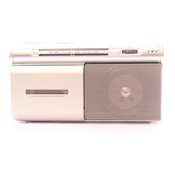
CFM-20
Model Name Using Similar Machanism
Tape Transport Mechanism Type
SPECIFICATIONS
RADIO CASSETTE-CORDER
AEP Model
UK Model
E Model
CFM-S1
MF-M20-117
Advertisement
Table of Contents

Related Manuals for Sony CFM-20


Summary of Contents for Sony CFM-20
-
Page 1: Specifications
CFM-20 SERVICE MANUAL AEP Model UK Model Ver 1.1 2002.10 E Model Model Name Using Similar Machanism CFM-S1 Tape Transport Mechanism Type MF-M20-117 SPECIFICATIONS RADIO CASSETTE-CORDER Sony Corporation 9-873-105-22 Personal Audio Company 2002J0200-1 Published by Sony Engineering Corporation © 2002.10... -
Page 2: Table Of Contents
MARK !ON THE SCHEMATIC DIAGRAMS AND IN THE PARTS LIST damaged by heat. ARE CRITICAL TO SAFE OPERATION. REPLACE THESE COMPONENTS WITH SONY PARTS WHOSE PART NUMBERS APPEAR AS SHOWN IN THIS MANUAL OR IN SUPPLEMENTS PUBLISHED BY SONY. SECTION 1... -
Page 3: Disassembly
CFM-20 SECTION 2 DISASSEMBLY • The equipment can be removed using the following procedure. Cabinet (front) sub ASSY Record/playback head (HRP101), Reel/capstan motor (M101), Belt Batt(+) board, Power board MD ASSY Cabinet (rear) ASSY Jack board, Main board Note : Follow the disassembly procedure in the numerical order given. -
Page 4: Record/Playback Head (Hrp101), Reel/Capstan Motor (M101),Belt
CFM-20 2-3. RECORD/PLAYBACK HEAD (HRP101), REEL/CAPSTAN MOTOR (M101), BELT • Attaching belt Flywheel ASSY Belt 9 Belt M101 MD ASSY 5 Lug (T), plate 4 Record/playback 8 Reel/capstan head (HRP101) motor (M101) 2 Guide, tape 6 Spring, Compr 3 Screws... -
Page 5: Batt (+) Board, Power Board (Aep, Uk, It, Cet, Hk, Sp, Ar Model)
CFM-20 2-5. BATT (+) BOARD, POWER BOARD (AEP, UK, IT, CET, HK, SP, AR model) Claw Batt (+) board Cabinet (rear) White 3 Screws (+ BVTP 3X10) Power board 2-6. BATT (+) BOARD, POWER BOARD (C&SA, MX, TW model) Cabinet (rear) - Page 6 CFM-20 • DIAL POINTER SETTING Note : Follow the installation procedure in the numerical order given. 4 Set the right side edge of Pointer to the center of three scratched lines Back plate on Back plate. Pointer Set Pointer to "Cabinet (front)"...
-
Page 7: Adjustments
CFM-20 SECTION 3 ADJUSTMENTS 3-1. MECHANICAL ADJUSTMENTS 3-2. ELECTRICAL ADJUSTMENTS PRECAUTION 0dB=0.775V TAPE RECORDER SECTION 1.Clean the following parts with a denatured-alcohol-moistened FUNOTION switch (S101) : TAPE (RADIO OFF) swab : VOLUME (RV101) : MIN record/playback head pinch roller erase head... - Page 8 CFM-20 Tape Speed Adjustment Procedure : level meter Speaker output:12Ω Mode : Playback Earphone jack:8Ω digital frequency test tape counter WS-48B Speaker output:12Ω (3kHz, 0dB) Earphone jack:8Ω AEP, UK, CET, IT, AR, HK, SP modelt J101 (Earphone jack) C&SA, MX, TW model t KH102 (Speaker output)
- Page 9 CFM-20 • Repeat the procedures in each adjustment several times, and the : C&SA, MX, TW model frequency coverage and tracking adjustments should be finally < > : IT model done by the trimmer capacitors. FM IF ADJUSTMENT Adjust for a maximum reading on level meter.
- Page 10 CFM-20...
-
Page 11: Diagrams
CFM-20 SECTION 4 DIAGRAMS 4-1. BLOCK DIAGRAMS • Abbreviation : Singapore • Signal path. : Hong Kong : FM : Argentina : AM : Mexican : PB : Italian : REC : Taiwan : MIC C&SA : Central and South America... -
Page 12: Printed Wiring Boards
CFM-20 4-2. PRINTED WIRING BOARDS ANT1 TELESCOPIC ANTENNA Semiconductor Location MAIN BOARD MAIN BOARD Ref. No. Location (C&SA,MX,TW) SP101 D101 SPEAKER D102 D103 D104 D106 M101 D107 REEL/CAPSTAN D108 MOTOR S501 (TAPE POWER) IC101 1-680-974- (11) HRP101 Q101 S101 REC/PB... -
Page 13: Schematic Diagrams -Main Section (1/2)
CFM-20 4-3. SCHEMATIC DIAGRAM – MAIN SECTION (1/2) – Refer to page 14 for Notes. Refer to page 14 for IC Block Diagrams. -
Page 14: Schematic Diagrams -Main Section (2/2)
CFM-20 Refer to page 14 for Notes. Refer to page 14 for IC Block Diagrams. 4-4. SCHEMATIC DIAGRAM – MAIN SECTION (2/2) –... - Page 15 CFM-20 Note on schematic Diagram: MAIN SECTION (1/2), (2/2) • All capacitors are in µF unless otherwise noted. pF: µµF 50 WV or less are not indicated except for electrolytics and tantalums. • All resistors are in Ω and W or less unless otherwise specified.
-
Page 16: Ic Block Diagrams
CFM-20 • IC BLOCK DIAGRAMS IC1 TA2132AF (EL) AM RF AM RF FM RF FM RF AM/FM AM/FM QUAD FM/AM BUFF FM RF FM RF FM IF AM IF IC101 MM1315BD – – – – – – –... -
Page 17: Exploded Views
CFM-20 SECTION 5 EXPLODED VIEWS NOTE : • -XX, -X mean standardized parts, so they • The mechanical parts with no reference The components identified by mark 0 may have some difference from the original number in the exploded views are not or dotted line with mark 0 are critical one. -
Page 18: Rear Cabinet Section
CFM-20 Ver 1.1 2002.10 5-2. REAR CABINET SECTION ANT1 C&SA, MX, TW not supplied C&SA, MX, TW AEP, UK, IT, CET not supplied HK, SP, AR The components identified by mark 0 or dotted line with mark 0 are critical for safety. -
Page 19: Mechanism Deck Section-1(Mf-M20-117)
CFM-20 5-3. MECHANISM DECK SECTION-1 (MF-M20-117) HRP101 HE101 Ref. No. Part No. Description Remark Ref. No. Part No. Description Remark 3-933-010-01 SPRING (S/P), TORSION 3-933-004-01 CLAW, REEL 3-933-025-01 SPRING (P), TORSION 3-933-021-01 SLIDER (FRP) 3-040-857-01 LEVER (P) 3-934-024-01 ROLLER, PINCH... -
Page 20: Mechanism Deck Section-2(Mf-M20-117)
CFM-20 5-4. MECHANISM DECK SECTION-2 (MF-M20-117) S501 M101 Ref. No. Part No. Description Remark Ref. No. Part No. Description Remark 3-933-029-01 LEVER, ERASING PREVENTION 3-933-020-01 BELT 3-933-182-01 SPRING, CASSETTE X-3377-877-2 FLYWHEEL ASSY 3-932-995-01 GEAR (MID) 3-932-993-01 CHASSIS, OUTSERT X-3371-667-1 CLUTCH ASSY... -
Page 21: Electrical Parts List
CFM-20 SECTION 6 BATT(+) JACK MAIN ELECTRICAL PARTS LIST NOTE : • Due to standardization, replacements in the • SEMICONDUCTORS The components identified by mark 0 In each case, u : µ , for example : parts list may be different from the parts or dotted line with mark 0 are critical uA.. - Page 22 CFM-20 MAIN Ref. No. Part No. Description Remark Ref. No. Part No. Description Remark C133 1-126-934-11 ELECT 220uF 1-424-726-11 COIL, AIR-CORE (FM OSC) C134 1-162-964-11 CERAMIC CHIP 0.001uF (FM FREQUENCY COVERAGE)(AEP,UK,CET) C135 1-162-970-11 CERAMIC CHIP 0.01uF 1-419-998-11 COIL, OSCILLATION (FM OSC)
- Page 23 CFM-20 Ver 1.1 2002.10 POWER Ref. No. Part No. Description Remark Ref. No. Part No. Description Remark POWER BOARD (C&SA,MX,TW) MISCELLANEOUS *********** ************* <CAPACITOR> X-3380-915-1 CABINET (FRONT) SUB ASSY (INCLUDING SP101)...(BLACK)(C&SA,MX,TW) C901 1-162-970-11 CERAMIC CHIP 0.01uF X-3380-916-1 CABINET (FRONT) SUB ASSY...
-
Page 24: Revision History
CFM-20 REVISION HISTORY Clicking the version allows you to jump to the revised page. Also, clicking the version at the upper right on the revised page allows you to jump to the next revised page. Ver. Date Description of Revision 2001.03...
Need help?
Do you have a question about the CFM-20 and is the answer not in the manual?
Questions and answers