Table of Contents
Advertisement
Advertisement
Table of Contents

Related Manuals for Woodward 82384

Summary of Contents for Woodward 82384
- Page 1 Installation and Operation Manual SPM-A Synchronizer Manual 82384 (Revision U)
- Page 2 Revisions—Text changes are indicated by a black line alongside the text. Woodward Governor Company reserves the right to update any portion of this publication at any time. Information provided by Woodward Governor Company is believed to be correct and reliable. However, no responsibility is assumed by Woodward Governor Company unless otherwise expressly undertaken.
-
Page 3: Table Of Contents
Dynamic Check ....................19 4. S ..............21 HAPTER ERVICE PTIONS Product Service Options..................21 Returning Equipment for Repair................22 Replacement Parts ....................23 How to Contact Woodward...................23 Engineering Services ...................24 Technical Assistance....................25 SPM-A S ........27 YNCHRONIZER ONTROL PECIFICATIONS Illustrations and Tables Figure 1-1. Control Outline Drawing...............5 Figure 1-2. -
Page 4: Electrostatic Discharge Awareness
PCB from the control cabinet, place it in the antistatic protective bag. CAUTION—ELECTROSTATIC DISCHARGE To prevent damage to electronic components caused by improper handling, read and observe the precautions in Woodward manual 82715, Guide for Handling and Protection of Electronic Controls, Printed Circuit Boards, and Modules. Woodward... -
Page 5: Chapter 1. General Information
Manual 82384 SPM-A Synchronizer Chapter 1. General Information Regulatory Compliance • The SPM-A Synchronizer is suitable for use in Ordinary Locations per CSA and/or UL for Canada and the U.S. or non-hazardous locations only. See table below for agency listed options. -
Page 6: Description
Select the low impedance output for single-unit synchronization when the engine is controlled by a Woodward 2301A, 2500, or Electrically Powered Governor (EPG) control through a Generator Load Sensor. Use the EPG output when using a Woodward EPG control without load sensing. Both units have the following features: •... -
Page 7: Theory Of Operation
If phase and frequency are within proper limits, the synchronizer issues the breaker closure command. (Voltage is not checked in the Permissive Mode.) See Woodward Application Note 50511 for information on the prediction of the phase angle at paralleling breaker closure. Woodward... - Page 8 SPM-A Synchronizer Manual 82384 Synchronizing the Generator The phase detector compares the two signals and determines any difference between the generator and bus phases. When there is a difference, the speed bias circuit sends a correction signal to the Load Sharing and Speed Control.
-
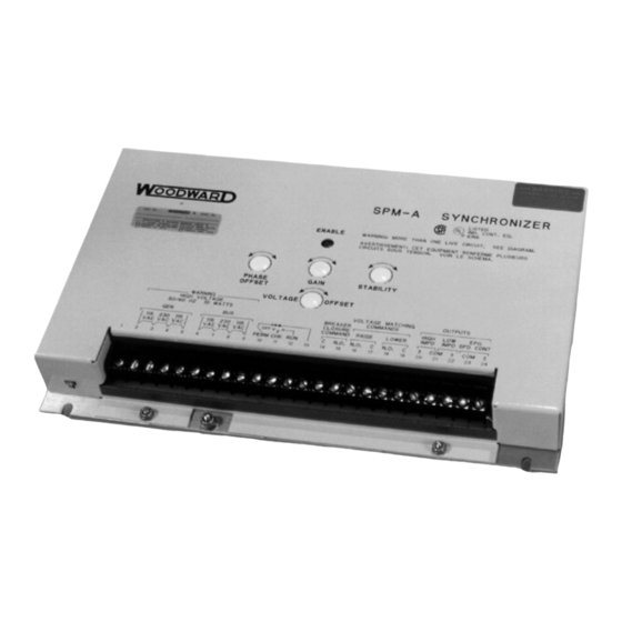
Page 9: Figure 1-1. Control Outline Drawing
Manual 82384 SPM-A Synchronizer Figure 1-1. Control Outline Drawing Woodward... -
Page 10: Figure 1-2. System Block Diagram
SPM-A Synchronizer Manual 82384 Figure 1-2. System Block Diagram Woodward... -
Page 11: Figure 1-3. Functional Block Diagram
Manual 82384 SPM-A Synchronizer Figure 1-3. Functional Block Diagram Woodward... -
Page 12: Figure 1-4. Plant Wiring Diagram
SPM-A Synchronizer Manual 82384 Figure 1-4. Plant Wiring Diagram Woodward... -
Page 13: Chapter 2. Installation
Manual 82384 SPM-A Synchronizer Chapter 2. Installation Introduction This chapter provides the general information for site selection, installation, and wiring of the SPM-A Synchronizer. Unpacking Before unpacking the synchronizer, refer to the inside front cover of this manual for WARNINGS and CAUTIONS. Be careful when unpacking the synchronizer. -
Page 14: Electrical Connections
The following instructions and wiring diagrams illustrate typical wiring connections. For applications not shown in Figures 2-1 and 2-2, refer to the plant wiring diagram (Figure 1-4) or contact Woodward for assistance. Connect the synchronizer terminals as shown in Figure 1-4. When making the connections, observe the following: •... -
Page 15: Connections To Load Sharing And Speed Control
EGM 2301A No resistor required Generator Load Sensor No resistor required Sequentially Paralleling Generator to a Bus Although the synchronizer can be switched to parallel generators in sequence to a bus, Woodward Governor Company does not recommend this option. Woodward... - Page 16 SPM-A Synchronizer Manual 82384 Voltage Regulator Relay Output Connections Make the connections as required to terminals 16 through 19 of the synchronizer. Terminals are shown in Figure 1-4, which give normally open contacts for operation to the voltage regulator. The ratings for the voltage raise and lower...
-
Page 17: Figure 2-1. Typical Spm-A Synchronizer Wiring
Manual 82384 SPM-A Synchronizer Figure 2-1. Typical SPM-A Synchronizer Wiring Woodward... -
Page 18: Figure 2-2. Synchronizing Bus To Bus
SPM-A Synchronizer Manual 82384 Figure 2-2. Synchronizing Bus to Bus Woodward... -
Page 19: Chapter 3. Calibration And Checkout Procedure
Notes in the text indicate when procedures are different for each SPM-A model. CAUTION—ELECTROSTATIC DISCHARGE Before attempting to calibrate the synchronizer, read Woodward Manual 82715, Guide for Handling and Protection of Electronic Controls, Printed Circuit Boards, and Modules. General Information... -
Page 20: Figure 3-1. Dwell Time Setting Switches
SPM-A Synchronizer Manual 82384 Remove the four elastic nuts securing the synchronizer cover. Remove the cover. CAUTION—ELECTROSTATIC DISCHARGE To prevent damage to the components of the synchronizer, read and follow the Electrostatic Discharge Awareness precautions on page ii. Set the dwell time using the four-position gang switch located in the upper left corner of the circuit board (see Figure 3-1). -
Page 21: Test And Adjustment
Manual 82384 SPM-A Synchronizer Test and Adjustment Bench Test A simple bench test may be done prior to installing the synchronizer. No adjustments can be made as a result of this test. The bench test only provides an indication of proper basic operation. - Page 22 SPM-A Synchronizer Manual 82384 Place the mode switch in the RUN position. The ENABLE indicator will be off, and the BREAKER CLOSURE contacts will be open. Place the mode switch in the OFF position. The ENABLE indicator will be off, and the BREAKER CLOSURE contacts will be open.
-
Page 23: Dynamic Check
Manual 82384 SPM-A Synchronizer Dynamic Check The best way to test and adjust the synchronizer is to operate it while in the CHECK mode. Place the mode switch (user supplied) in the OFF position for starting. Apply power to the electronic governor and start the engine according to the manufacturer's instructions. - Page 24 SPM-A Synchronizer Manual 82384 Phase Offset Adjustment If the synchroscope steadies at other than 0 (zero) degrees (in the CHECK mode), the phase offset potentiometer may need adjustment. Note the potentiometer position before changing the setting. Turn the potentiometer as necessary to center the indicator of the synchroscope.
-
Page 25: Chapter 4. Service Options
Product Service Options The following factory options are available for servicing Woodward equipment, based on the standard Woodward Product and Service Warranty (5-01-1205) that is in effect at the time the product is purchased from Woodward or the service is performed: •... -
Page 26: Returning Equipment For Repair
Returning Equipment for Repair If a control (or any part of an electronic control) is to be returned to Woodward for repair, please contact Woodward in advance to obtain a Return Authorization Number. When shipping the item(s), attach a tag with the following information: •... -
Page 27: Replacement Parts
To expedite the repair process, contact Woodward in advance to obtain a Return Authorization Number, and arrange for issue of a purchase order for the item(s) to be repaired. No work can be started until a purchase order is received. -
Page 28: Engineering Services
SPM-A Synchronizer Manual 82384 Engineering Services Woodward Industrial Controls Engineering Services offers the following after- sales support for Woodward products. For these services, you can contact us by telephone, by email, or through the Woodward website. • Technical Support •... -
Page 29: Technical Assistance
Type of Fuel (gas, gaseous, steam, etc) Rating Application Control/Governor Information Please list all Woodward governors, actuators, and electronic controls in your system: Woodward Part Number and Revision Letter Control Description or Governor Type Serial Number Woodward Part Number and Revision Letter... - Page 30 SPM-A Synchronizer Manual 82384 Woodward...
-
Page 31: Spm-A Synchronizer Control Specifications
SPM-A Synchronizer Control Specifications Woodward Part Numbers: 9905-001/9907-028 50/60 Hz, ±10° phase angle, no voltage matching 9905-002/9907-029 50/60 Hz, ±10° phase angle, 1% voltage matching 9905-003 50/60 Hz, ±10° phase angle, 5% voltage matching 9905-004 50/60 Hz, ±5° phase angle, no voltage matching 9905-005 50/60 Hz, ±5°... - Page 32 Phone +1 (970) 482-5811 • Fax +1 (970) 498-3058 Email and Website—www.woodward.com Woodward has company-owned plants, subsidiaries, and branches, as well as authorized distributors and other authorized service and sales facilities throughout the world. Complete address / phone / fax / email information for all locations is available on our website.
Need help?
Do you have a question about the 82384 and is the answer not in the manual?
Questions and answers