Table of Contents
Advertisement
MANUAL FOR MODEL FD4 FIRE PUMP CONTROLLERS
This manual provides General Information, Installation, Operation, Maintenance and System Set-Up Information for METRON Model
FD-4 Engine Driven Fire Pump Controllers.
PART I
General Information ........................................................................................................................................ PAGE 3
PART II
Functions ......................................................................................................................................................... PAGE 3
PART III
Operation of the Controller ............................................................................................................................. PAGE 4
PART IV
Installation & Test Procedure ......................................................................................................................... PAGE 5
PART V
Additional Optional Features ......................................................................................................................... PAGE 9
PART VI
Operator Interface Device (OID) Use and Navigation ........................................................................ PAGE 10
PART VII
System Set Point Definitions ........................................................................................................................ PAGE 18
PART VIII
Alarm and Event Log Messages ................................................................................................................... PAGE 22
PART IX
SD Card File Format .................................................................................................................................... PAGE 25
Appendix A
Modbus Protocol ........................................................................................................................................... PAGE 29
Metron, Inc.
Revision: P
Firmware version 5.02
TABLE OF CONTENTS
METRON, INC.
Hubbell Industrial Controls Inc.
4301 Cheyenne Drive, Archdale, NC 27263
www.metroninc.com
Telephone: (336) 434-2800 Ext. 183
Date:
03/22/04
Date:
03/15/15
Approved:
MH
Approved:
RA
DOC#:
586
Page:
1 of 34
Advertisement
Table of Contents

Subscribe to Our Youtube Channel
Related Manuals for METRON FD4


Summary of Contents for METRON FD4
- Page 1 MANUAL FOR MODEL FD4 FIRE PUMP CONTROLLERS Firmware version 5.02 This manual provides General Information, Installation, Operation, Maintenance and System Set-Up Information for METRON Model FD-4 Engine Driven Fire Pump Controllers. TABLE OF CONTENTS PART I General Information ............................PAGE 3 PART II Functions .................................
- Page 2 THIS PAGE IS BLANK Page 2 of 34 File Name: Doc#586p.docx...
- Page 3 PART I: GENERAL INFORMATION The basic function of the model FD4 Fire Pump Controller for diesel engine driven fire pumps is to automatically start the engine upon a drop in pressure in the water main, or from a number of other demand signals. This controller provides automatic cycled cranking, alarm and/or alarm shutdown protection for various engine failures.
- Page 4 F. A data logger is provided as standard to record system pressure along with numerous alarm conditions and system events. The data can be displayed on the OID or can be downloaded to a PC through the RS485 port provided on the main system board. Data is stored on an SD Memory card.
- Page 5 In case of Overspeed, the engine will be stopped and the "Engine Overspeed" light will illuminate and the alarm will sound. The light and alarm will stay on until the Engine Speed Switch and the Controller are manually reset. To manually reset the Controller, turn the controller selector switch to Off, then press the Reset button.
- Page 6 wire must be wired from the grounding lug in the controller to earth ground. In most cases, the engine manufacturer furnishes the engines with all accessories installed and wired to the connection box. Therefore, it is only necessary to wire from the engine connection box to like numbered terminals in the Controller.
- Page 7 duration. The "Failed to Start" light should come on and the alarm horn should sound. Status indicator light for Terminal #1 should come on as soon as the "Test" push button is pressed and the pressure drops below the low set point.
- Page 8 The periodic Weekly Test function is factory set to No in Screen 106 due to Factory Mutual standard requirements. Contact the Metron Factory Service department for instructions to turn this function on if this is not a Factory Mutual insured facility.
- Page 9 FOAM PUMP OPTION: An optional feature to operate an external pressure dump valve can be provided for Foam Pump Service if required. Screen 318 is set to approximately 10-15 seconds to operate a dry contact which can be used to operate the Dump Valve solenoid.
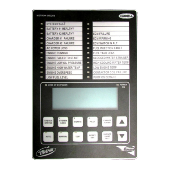
- Page 10 PART VI: OPERATOR INTERFACE DEVICE (OID) USE AND NAVIGATION The Operator Interface Device (OID) provides visual indication of the alarms, status of system parameters, and an interface to change set points to configure the FD4 to operate appropriately for various installation requirements. Labeled LED...
- Page 11 OID Screen Map METRON OID202 LOSS OF DC POWER POWER SYSTEM SYSTEM CHANGE/ CONFIG PILOT STATUS ENTER LOGS SILENCE RESET/ AUTO MANUAL TEST /LAMP TEST SYSTEM STATUS B1 SYSTEM LOGS CONFIG PRES STRT BAT1 BAT2 1) Event Log 1) SYSTEM SETPOINTS...
- Page 12 OID Screen Map (continued) Note: Sample settings shown below. Not to be used to program controller for operation. Consult factory for correct settings for the site conditions. CONFIG 1) SYSTEM SETPOINTS 2) USER PREFERENCES 24v Defaults 3) TECH SCREENS CONFIG FD4e v5.00 1) ANALOG SIGNALS 2) AUX USER PROGRAMS...
- Page 13 OID Screen Map (continued) 116 SYSTEM SETPOINTS 219 USER PREFERENCES 429 BATTERY 1 AUX SETPOINTS 319 TECH SCREENS Shutdown On Low Charger failure Pressure Minimum Amps Aux User Program # 1 Transducer Intake Pressure/Lvl delay time Shutdown in Test [No ] 5]seconds 0-999 [Yes]...
- Page 14 Use the [UP] and [DOWN] buttons to scroll between the two menu screens. Buttons with numbers on them can be used to enter the selected configuration screen group. See the Configuring the FD4 section for descriptions on the functionality of each set point. SYSTEM STATUS...
- Page 15 SYSTEM LOGS: The FD4 has three separate data logs; 1) alarm log, 2) event log, and 3) pressure log. The alarm log is a subset of the event log and only displays the last ten alarms that have occurred or cleared. The event log records all alarm and...
- Page 16 Typical Event/Alarm Log Message Printout EVENT LOG AC Power Restored EVENT LOG Occurred On AC Power Restored 06/15/10 07:32:15 Occurred On 06/15/10 07:32:15 EVENT LOG AC Power Restored Occurred On 06/15/10 07:32:15 EVENT LOG AC Power Restored Occurred On Typical Event/Alarm Log 06/15/10 07:32:15 Details Printout EVENT DETAILS...
- Page 17 CONFIGURATION SCREENS: All parameters that control the operation of the controller can be viewed and changed within the Configuration set point screens. Each set point is protected by a user password to prevent unauthorized changes. The system set points are separated into five different group CONFIG 1) SYSTEM SETPOINTS (Level 1 password): These setpoints adjust the conditions 1) SYSTEM SETPOINTS...
- Page 18 107 and 108 [Yes] below. Requires the Tech password to change. Contact Metron Factory. 107 SYSTEM SETPOINTS The day of the week that the automatic weekly test start will begin.
- Page 19 112 SYSTEM SETPOINTS When set point 111 above is enabled, set this timer for the length of time desired Power Failure Engine to sense a loss of AC power and override any momentary outages. Start Delay Time [ 1] minutes 0-500 113 SYSTEM SETPOINTS When this feature is enabled, the controller will start the engine if a faulty pressure...
- Page 20 Engine Lockout required to stop the engine after an automatic stop, or prevent it starting Latched automatically. Can only be activated at the factory by Metron. [No] 124 SYSTEM SETPOINTS This setting whether contact for remote start is either Normally Open (NO) or...
- Page 21 213 USER PREFERENCES Set to English or Spanish Language Select 0=English 1=Spanish [English] 214 USER PREFERENCES Used to set the password necessary to access the System config screens. Change User Password Level 1 [****] 215 USER PREFERENCES Used to save auxiliary alarm configuration parameters to the SD card Save All Settings to SD card [No]...
- Page 22 Start Alarm Cleared OFF mode to reset this alarm. Engine Quit FD4 controller lost the engine run signal from the engine while it was running in Alarm Occurred/ Auto mode. This could be a bad wire connection or a problem on the engine that Alarm Cleared shut the engine down other than an overspeed or failed to start condition.
- Page 23 A deluge start signal was received while in Auto mode. Occurred Cleared Controller Reboot DC power was restored to the FD4 microprocessor. Occurred Pressure Drop If setpoint #204 is set to yes, this event gets recorded when the system pressure Occurred drops below the setting in setpoint #205.
- Page 24 Internal and External variables Aux Alarm Text List Messages List of possible internal variables used as inputs for aux alarm user programs. Auxiliary Alarm High Fuel Level Low Oil Pressure Fuel Spill General Battery Fault Fuel Tank Rupture Engine Quit Alarm Low Pump Room Temp Pressure Transducer Fault Reservoir Low Low Intake Shutdown Alarm...
- Page 25 PART IX - SD CARD FILE FORMAT. The controller is equipped with an SD (Secure Digital) memory card on the motherboard to store the Pressure log, Event log, Operators Manual in PDF format, Auxiliary Alarm configuration information and the controller drawings in PDF format. The SD card is located on the right hand edge of the motherboard and is removed by pressing in on the right edge of the card to release from the card holder.
- Page 26 Original firmware, Metron Eledyne use only. FW_DEF.TXT A file containing the version number of the FD4FW.HEX firmware file. Metron Eledyne use only. SETTINGS.TXT This file is created when ‘save all settings’ is executed from the controller, contains the saved settings.
- Page 27 Enhanced Data Logging Pressure Logging: When it is time to log the pressure the system tries opens a pressure log file with a number at the end that corresponds with the day of the month. If the file doesn’t exist it just creates it and logs the pressure. If the file does exist it reads the first record to see if the month matches the current month. If it does match the pressure is logged at the end of the file if not the file is archived based on the date of the first record in the file. A new file is open and the pressure is logged. LOGSyy\PRESmmdd.TXT for the pressure log file. Events Logging: And LOGSyy\mmddhhMM.TXT for the events file. Page 27 of 34 File Name: Doc#586p.docx...
- Page 28 FD4 SD Card Compatibility Chart: Make Model Type Speed Size Price(£) Date Result FW (01‐Aug‐13) Update SanDisk SDSDB‐002G‐B35 4.50 05‐Aug‐13 Pass Pass SanDisk SDSDB‐004G‐B35 SDHC 3.73 05‐Aug‐13 Pass Pass ...
- Page 29 Appendix A RS485 Port Usage For Serial Modbus RTU protocol: The Modbus option on the fire pump controller boards can be enabled by disabling the printer option to the onboard RS485 port. All communications to this port will be in a 2 wire RS485 format. 255 controllers can communicate on a single network. The pinout cabling required for connection to the port is as follows.
- Page 30 Real Time Event Monitoring: All events listed below in figure 1.2 are real time and can be viewed in Modbus register 40002. Figure 1.2 depicts the 16 bit breakdown and cross reference. This is not to be confused with the historical event log. Description Modbus Registers Usage Notes For Read Only Registers...
- Page 31 Setting And Reading The Real Time Clock Through Modbus: Modbus registers 40007 through 400013 are real time clock read registers as seen in figure 1.3. To set the clock current values must be entered into registers 40014 through 40020. Any of these registers left to zero will result in an incorrect clock setting. Once desired clock date and time values are entered bit 0 of register 40001 must be toggled for the controller to accept the values.
- Page 32 It is recommended to set the log to the most current entry before scrolling. When scrolling, it is possible to move forward and backward through roughly a full weeks worth of data. See figure 1.5 for register interpretation. Description Modbus Registers Usage Notes For Read Only Registers Event Historical Log Index 040107...
- Page 33 Event/Alarm Description Event Index # Event/Alarm Description Event Index # High Engine Oil Temperature Alarm Occurred Auto Test Start Event Occurred High Engine Oil Temperature Alarm Cleared Auto Test Start Event Cleared Low Jacket Water Flow Alarm Occurred Alarm Reset Button Pressed Event Occurred Low Jacket Water Flow Alarm Cleared Alarm Reset Button Pressed Event Cleared Low Jacket Water Level Alarm Occurred...
- Page 34 Historical Pressure Readings: The historical pressure readings can be viewed from Modbus registers 40122 through 40129. Here it is possible to scroll through the entire log and set the log pointer to the most current record. Register 40122 contains a number representing the actual log number entry location in the controller.
Need help?
Do you have a question about the FD4 and is the answer not in the manual?
Questions and answers