
Summary of Contents for Jensen JRVCS1
- Page 1 JRVCS1 RV CONTROL AND MONITORING SYSTEM Installation and Operation Manual...
-
Page 2: Table Of Contents
JRVCS1 CONTENTS CONTENTS ..........................ii Introduction ..........................4 Thank You!..........................4 Features..........................4 Precautions ........................... 4 Packing List .......................... 4 Installation ............................ 5 Tools and Supplies........................ 5 Disconnecting the Battery..................... 5 ... - Page 3 JRVCS1...
-
Page 4: Introduction
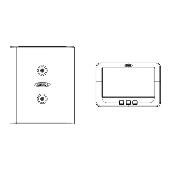
Packing List Thank You! Thank you for choosing a Jensen product. We hope you will find the instructions in this owner’s 1 Cover, 2 Thumb Screws 1 Body Control Module (BCM) 1 Display Commander (DC) manual clear and easy to follow. If you take a few minutes to look through it, you’ll learn how to use all the features of your new Jensen JRVCS1 for maximum enjoyment. -
Page 5: Installation
It’s a good idea to read all of the instructions before beginning the installation. We recommend having your Jensen JRVCS1 installed by a reputable RV dealership Tools and Supplies You will need these tools and supplies to install your JRVCS1: Phillips screwdriver ... -
Page 6: Wiring
JRVCS1 WIRING The wiring diagram depicts all the wiring connections required for proper operation of the unit. BODY CONTROL MODULE (BCM) CONNECTIONS 刪除: PIN NO. WIRE COLOR/SIZE DESCRIPTION BODY CONTROL MODULE (BCM) CONNECTIONS GREEN (18) GEN PRIME/STOP +12V (OUT) PIN NO. - Page 7 JRVCS1 BODY CONTROL MODULE (BCM) CONNECTIONS PIN NO. WIRE COLOR/SIZE DESCRIPTION (10) FRONT JACKS (OUT) (10) FRONT JACKS (OUT) WHITE (10) ELECTRIC SLIDE 5 -12V (OUT) PURPLE (10) ELECTRIC SLIDE 5 +12V (OUT) WHITE (10) ELECTRIC SLIDE 4 -12V (OUT)
-
Page 8: Troubleshooting
JRVCS1 SLIDE 1 ELECTRIC OR HYDRAULIC SLIDE 2 ELECTRIC OR HYDRAULIC SLIDE 3 ELECTRIC OR HYDRAULIC SLIDE 4 ELECTRIC OR HYDRAULIC SLIDE 5 ELECTRIC OR HYDRAULIC TRIGGER 1 MOMENTARY OR LATCH TRIGGER 2 MOMENTARY OR LATCH TRIGGER 3 MOMENTARY OR LATCH... -
Page 9: Specifications
Maximum Operating Voltage ..........16vdc JRVCS1 System EPROM Non-Volatile Memory . -
Page 10: Fcc Notes
JRVCS1 FCC Notes 格式化: 置中 Body Control Module ....... . 14.7” (W) x 17.87” (D) x 1.75” (H) Display Commander . - Page 11 SETUP Text Editing 1. Select “setup” 2. Long press “Awning1” ...
- Page 12 3. A device rename window will open. Press “OK” after completing the text editing. ...
- Page 13 ...
- Page 14 SETUP Scroll List Editing 1. Select “setup” Î 2. Press the “ ” icon before the device name and move the device to a new location, “Electric Slide 1” as an example. ...
- Page 15 SETUP Triggers 1. Triggers 1 through 8 can be added to the system. ...
- Page 16 2 Either “Momentary” or “Latch” can be selected for each Trigger. ...
- Page 17 SETUP Tanks 1. Fresh water tanks, Black water tanks and Gray water tanks can be added to the system, ...
- Page 18 ...
- Page 19 SETUP Lights 1. Light Groups can be added to the system, ...
- Page 20 SETUP Slides 1. Slides can be added to the system, ...
- Page 21 SETUP Awnings 1. Awnings can be added to the system, ...
- Page 22 SETUP Jacks 1. Jacks can be added to the system, ...
- Page 23 SETUP Passcode 1. Select “Setup”. 2. Press “Lock” to enter passcode setup. ...
- Page 24 3. The passcode setup window will open. (DEFAULT FACTORY SETTING IS “ON”) ...
- Page 25 3.1 Turn on Passcode Protection 3.1.1. Press “On” to turn on passcode protection. The system will request a passcode. (5391) ...
- Page 26 3.1.2. Select the idle time to activate the passcode protection. ...
- Page 27 3.1.3 Passcode protection is activated. ...
- Page 28 3.2 Turn OFF Passcode protection 3.2.1. When passcode protection is ON, press “On” button to turn off passcode protection ...
- Page 29 3.2.2. Read the passcode ”Off” disclaimer statement and press “Accept” to proceed. ...
- Page 30 3.2.3 Enter passcode to proceed 3.2.4. Passcode protection is now turned off. ...
- Page 31 3.3 Change Passcode 3.3.1. Press the “Edit” button to change to a new passcode. ...
- Page 32 3.3.2. Enter the old passcode. ...
- Page 33 3.3.3. Enter the new passcode. ...
- Page 34 ...
- Page 35 3.3.4. Confirm new passcode. PAIRING INSTRUCTIONS ...
- Page 36 DC to BCM 1. Select “Setup” 2. Select “Maintain” ...
- Page 37 3. Currently, it shows no Bluetooth Low Energy device connected to this DC. Press the “Select” button across from the “BLE Device”. ...
- Page 38 4. The DC will find and list all available devices. ...
- Page 39 5. Press the target BCM to connect, “JENSENBCM 037EA0” as an example. 6. The DC will automatically return to the previous page and show the paired BCM. ...
- Page 40 7. Press the hot key to exit the “Maintain” setup page and the DC will start to connect to the selected BCM. ...
- Page 41 BCM to DC BLE connection is activated by the DC. The BCM only needs to power up. There is no action needed from the BCM. ...
- Page 42 PAIRING INSTRUCTIONS Mobile Device to DC 1. DC side. 1.1 Select “Setup”. 1.2. Select “Bluetooth”. ...
- Page 43 1.3. Currently, it shows no BT paired device connected to this DC. Press the “Discover” button to activate the BT pairing mode. ...
- Page 44 1.4. Press “Allow”. ...
- Page 45 2. Mobile Device side. 2.1 Press “Bluetooth” on the “Setup” page to find the DC device. ...
- Page 46 2.2. The Mobile APP will scan for the DC device. ...
- Page 47 2.3. Find the “DC” in the unpaired device list. Press “DC device” to pair with it. ...
- Page 48 ...
- Page 49 3.2 The DC now shows the Mobile device is paired. Software Update 1. Select “Setup”. ...
- Page 50 2. Attach the update software USB Drive before selecting “Maintain”. ...
- Page 51 3. The system will look for specific file names for software updates and turn on “Select” action buttons accordingly. ‐ File name: “JRVCS1_AP Vxxxx.apk” DC APP update, (xxxx is version number) ‐ File name: “JRVCS1_CM Vxxxx.bin” BCM update, (xxxx is version number) ‐ File name: “update.zip” DC Android OS update ...
- Page 52 ...
- Page 53 3.1. Press the APP “Update” button to update DC APP. ...
- Page 54 3.2. Press the BCM “Update” button to update the BCM firmware. ...
- Page 55 ...
- Page 56 3.3 Press the DC “Update” button to update DC Android OS. ...
- Page 57 ...
- Page 58 Reset Floor Plan 1. Select “Setup”. 2. Press “Default” to restore the system to previous settings. ...
- Page 59 3. Select “Floor Plan” to restore the previous floor plan setting. Current settings will be lost. ...
- Page 60 4. Select “Factory” to restore back to ASA default settings. Current settings will be lost. ...
- Page 61 ...
- Page 62 ASA Electronics Corporation www.asaelectronics.com www.jensenrvdirect.com ©2015 ASA Electronics Corporation...
Need help?
Do you have a question about the JRVCS1 and is the answer not in the manual?
Questions and answers