Table of Contents
Advertisement
Advertisement
Table of Contents

Related Manuals for DRE Waveline Plus

Summary of Contents for DRE Waveline Plus
- Page 1 DRE Waveline Plus Service Manual...
-
Page 2: Table Of Contents
SECTION 4 Troubleshooting ..............4-1 SECTION 5 Assembly demonstration ............5-1 SECTION 6 Technical Drawings..............6-1 A. System Configuration ..............6-1 B. Schematic Drawing ..............6-1 C. PCB Component Layout and Test Points........6-1 SECTION 7 Spare Parts List..............7-1 DRE, Inc. www.dremed.com... -
Page 3: Section 1 General Introduction
Section 1 General Introduction A. About The Service Manual 1. Objective: The Service manual is mainly used by biomedical equipment technicians and service personnel. Users shall have sufficient electronic technology background, including analog and digital electronics as well as computer technology. 2. - Page 4 The user of the monitor must be qualified persons who have been trained and are capable of using the monitor correctly. To protect patients’ safety, use only parts and accessories manufactured or recommended by the Company. Before connect the equipment to any other equipment not recommended in the manual, please contact the Company in advance.
-
Page 5: Service Information
Classified according to type of electric shock protection: Class I, with internal power supply. Classified according to degree of electric shock protection: BF type applied part – NIBP, SpO2, Temperature. CF type applied part – ECG, Respiration, invasive blood pressure. Classified according to degree of harmful liquid protection: common equipment (enclosed equipment without protection against liquid going in). -
Page 6: Section 2 Device Introduction
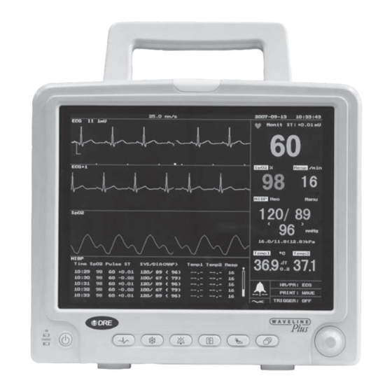
Section 2 Device Introduction A. Product Description The monitor is easy to carry, advanced function, easy to use. 1. Dimension 320mm W x 250mm H x170mm D 2. Weight 7.95 Kg 3. Screen 10.4" The device can be linked with central station. 4. - Page 7 (1) Handle This handle is convenient for operator to carry the patient monitor. (2) Screen TFT screen for displaying waveform, menu, alarm status and vital sign measurement results. (3) Power When the patient monitor is powered on, the LED is in green. Indicator When the patient monitor is connected to AC power supply but not turned on, the LED is in orange, indicating that the internal...
-
Page 8: Rear Panel
C. Rear Panel The rear panel of Omni is as shown in Figure 3-2. Fig. 3-2 Rear Panel Diagram 1. Handle 2. Product label 3. Fuse 1 4. 110-230VAC, 50/60Hz, external power supply socket 5. Fuse 2 6. Equipotentiality 7. Heat Exhaust 8. -
Page 9: Side Panels
D Side Panels There are seven sockets/receptacles on the left side panel, respectively: This socket accepts ECG cable accompanying the patient monitor. This socket accepts SpO extension cable. NIBP This receptacle accepts the hose connector plug from the blood pressure cuff. TEMP1 This receptacle accepts the temperature probe. - Page 10 t8 hours Charge time t1.5 hours (full recharge) Operating time Battery Charging Method Automatic charging after monitor is connected to AC power supply (with charge protection function) Discharge Protection When powered by battery, the monitor will be automatically turned off when battery power is almost used up. 3.
- Page 11 Measure Range 50 ~ 100% Averaging 8 second average r2% (90 ~ 100%), r3% (50 ~ 89%) Accuracy Pulse Rate Range 30 ~ 250 bpm Pulse Rate Averaging 8 beat average r1% ( 30 ~ 100 bpm) Pulse Rate Accuracy Sensor Types Finger, Universal “Y”, wrap probes Pulse Rate Display...
- Page 12 Transducer sensitivity 5uV/V/mmHg Alarm Audio and Visual Refurbish time about 2 seconds (6) Temperature (Dual Channel) Number of channels Measure range 0 ~ 50qC Probe type YSI Series 400 Scale Celsius r0.1qC Accuracy Resolution 0.1qC Refurbish time about 1 second 4.
-
Page 13: Requirements
F. Requirements Power requirement At least one grounded duplex wall receptacle should be provided for each monitor. 2. Ventilation requirement The monitor will produce heat while working. So the monitor should be located in a ventilated place. Caution. Do not locate the monitor in an enclosed area that may restrict the heat dissipated by it. -
Page 14: Section 3 Maintenance And Calibration
Section 3 Maintenance and Calibration A. Maintenance Plan To maintain the normal running of the monitor, a good maintenance plan must be made. We recommend the following: 1. Visual inspection: Before use, operator shall first inspect the outside appearance of the equipment. -
Page 15: Cleaning
D. Cleaning 1. Clean the display screen Use a soft cloth soaked in glass detergent to gently wipe the screen. Caution: Do not spry glass detergent or other detergent directly to the screen. Do not use medical disinfectant to clean the screen. 2. - Page 16 showing that the monitor is powered by battery. (4) Conduct ECG test according to the following instructions. (5) Reconnect the monitor to AC power and start the tests. 3. ECG test (1) Set the ECG simulator as follows: Heart rate: 80bpm, ECG gain: 1mV (2) Connect one end of the ECG cable and leadwires to the ECG connector of the monitor and the other end to the simulator.
- Page 17 pressure function. (1) Set the simulator as follows: blood pressure output: ATM (2) Connect one end of the BP cable to the BP1 socket on the simulator, the other end to the IBP1 socket on the monitor. (3) Press Zero in the IBP menu. (4) Select ART to be the blood pressure measurement position.
-
Page 18: Electricity Safety Test
calibration is complete. If not, re-calibration is required. If the same results cannot be obtained through repetitive calibration, please contact manufacturer. 9. Speaker Test (1) Turn on alarm sound and set Heart Rate alarm limits. Test if the monitor will make alarm sound when heart rate is outside alarm limits. -
Page 19: Section 4 Troubleshooting
Section 4 Troubleshooting A. Special Components Surface Mounted Devices Surface mounted devices are used to aid in miniaturizing the electrical assemblies within the monitor. Warning: Surface mounted components were not designed to be removed or replaced using standard soldering equipment. Removal of surface mounted components using a conventional soldering iron can potentially destroy the PCB. - Page 20 Solution: Replace ECG electrodes and clean the skin surface where electrodes are applied. Resistance of should exist between extension wires applied to patient body to the leads of the ECG connector. If it is indefinitely large, it shows that the leadwire is broken and should be replaced.
- Page 21 properly grounded. 5 Weak Respiration Signal Phenomenon: The respiration waveform is too low to examine. Inspection method: Check if the ECG electrodes are located correctly and if the ECG electrodes contact with patient’s skin is well. Solution: 1)Apply the ECG electrodes as Fig. 4-2 in P4-5 show, clean the skin surface where electrode is applied.
- Page 22 9 Low Inflation Pressure Phenomenon: During blood pressure measurement, the inflation pressure keeps to be low. Inspection method: Check if the NIBP cuff or extension tube is broken. Solution: Replace it with good NIBP cuff and extension tube. 10 Abnormal IBP Values Phenomenon: Displayed IBP values are different than expected.
- Page 23 Respiratory wave speed can be selected among 6.25/12.5/25.0mm/s. Default is12.5. Respiratory waveform fill-in or not can be selected between Yes/No. Default is No. In addition, menu can also be used to set the waveform speed. The steps are Waveline Plus OPERATOR’S MANUAL PAGE 5-1...
-
Page 24: Trend Display
At the bottom of the time status box, the display status bar filled or not shows whether a single page display of all trends have been completely displayed. When a single page PAGE 5-2 Waveline Plus OPERATOR’S MANUAL... - Page 25 Waveform recall refers to the recent 6-minute ECG waveform recall. When a patient’ ECG waveform is abnormal, the waveform can be recalled this way. To enter waveform recall screen, follow the procedure: Æ Rotate Knob Æ Æ Press Knob Recall MAIN MENU Waveline Plus OPERATOR’S MANUAL PAGE 5-3...
- Page 26 NIBP data window. The monitor has the following printing speed selections: Auto/12.5/25.0 mm/s. Default is Auto. To select printing speed: Æ Rotate Knob Æ Æ Press Knob Æ Rotate Knob Æ Print MAIN MENU PAGE 5-4 Waveline Plus OPERATOR’S MANUAL...
- Page 27 5.5 Volume Setup According to the various needs of users, the monitor has a VOLUME menu as follows, User may select the Alarm Volume or Heart Rate/Pulse Rate Volume and adjust the Waveline Plus OPERATOR’S MANUAL PAGE 5-5...
-
Page 28: System Setup
Rotate the knob to change the day, month and year. The information will not be updated in the system until the knob is pressed. 5.6.3 Language To select English language, Æ Rotate Knob Æ Setup Æ Press Knob Æ Rotate Knob MAIN MENU PAGE 5-6 Waveline Plus OPERATOR’S MANUAL... - Page 29 MAIN MENU Setup Default Æ Press Knob Æ Rotate Knob Æ Press Knob press the knob In the end, after system setup is completed, rotate the knob to EXIT , to confirm and quit. Waveline Plus OPERATOR’S MANUAL PAGE 5-7...
-
Page 30: Section 6 Technical Drawings
Section 6 Technical Drawings A. System Configuration Omni system configuration diagram is as follows GS AR42 4F4K01A RECORDER KEYBOARD (GSI) +15VDC(J2) KEY PORT GLM75-15 +15VDC POWER PORT POWER 200VAC (J1) NIBP MODULE SYSTEM PORT (P1) +12VDC ACID-LEAD BATT CUFF PORT £¨J1£©... -
Page 31: Section 7 Spare Parts List
Section 7 Spare Parts List NAME TYPE PC104 System Board 4F5S01C ECG Board 4F5E01C IBP Board 5A1I01B 71552B1 Board 71802B1 Key Board 4F3K01C Printer LCD Screen 10.4TFT Power Supply 12VDC or 15VDC Battery Frame EtCO board...
Need help?
Do you have a question about the Waveline Plus and is the answer not in the manual?
Questions and answers