Table of Contents
Advertisement
Quick Links
Advertisement
Table of Contents

Related Manuals for iS5 iSG4F

Summary of Contents for iS5 iSG4F
- Page 1 Intelligent Flexible Secure Gateway IEC 61850-3 and IEEE 1613 compliant iSG4F User’s Manual Version 1.1 September 2014 iS5 Communications Inc. #3-7490 Pacific Circle Mississauga, Ontario, L5T 2A3 Tel: + 905 670 0004 Fax: + 289 401 5201 Website: www.iS5Com.com E-mail:...
-
Page 2: Contact Information
DISCLAIMER Information in this publication is intended to be accurate. iS5 shall not be responsible for its use or infringements on third-parties as a result of its use. There may occasionally be unintentional errors on this publication. iS5 reserves the right to revise the contents of this publication without notice. -
Page 3: Table Of Contents
CAUTION: SERVICE ..................9 CAUTION: PHYSICAL ACCESS ..............9 Getting to Know Your Router ..............10 About the iSG4F Intelligent Flexible Secure Gateway ..............10 Software Features ..........................10 Hardware Features ..........................10 Hardware Overview ..................11 Front Panel ............................11 Rear ............................... - Page 4 User’s Manual 6.5.1 Safe Mode View ..........................23 6.5.2 SW Image Installation ........................25 Ethernet Port Interfaces ................27 Commands Hierarchy ........................28 Port Commands Example ........................ 28 Login and Management ................30 Serial Console Port ......................30 8.1.1 Connecting to the Console Port ..................
- Page 5 User’s Manual 11.2 Alarm Relay Contact Capabilities ..................46 11.3 Supported Alarms ......................46 11.3.1 SFP port state ........................46 11.3.2 L2 VPN state ........................46 11.3.3 System up/down ......................46 11.4 Default state ........................46 11.5 Commands Hierarchy ...................... 46 11.6...
- Page 6 User’s Manual 18.3 Serial Commands Hierarchy ..................... 70 18.4 Serial Commands Description ..................71 18.5 Declaration of ports ......................74 18.6 Serial Port Default State ....................75 18.7 RS- 232 Port Pin Assignment ................... 75 18.8 RS- 232 Serial cable ......................76 18.9...
- Page 7 User’s Manual 21.2 Terminal Server Commands Hierarchy ................100 21.3 Terminal Server Commands ................... 101 21.4 Example local Service ....................107 21.5 Example Networking ..................... 111 Modbus Gateway ..................113 22.1 Modbus Gateway Implementation ................. 113 22.2 Modbus Gateway Commands Hierarchy ................ 113 22.3...
- Page 8 User’s Manual 25.2.1 SIM card state ........................ 144 25.2.2 Backup and redundancy ....................146 25.3 GPRS/UMTS Commands Hierarchy ................147 25.4 GPRS/UMTS Commands Description ................148 25.5 Default State ........................152 25.6 Led States ........................152 25.7 Example for retrieving the IMEI ..................152 25.8...
-
Page 9: Caution: Laser
This product contains no user-serviceable parts. Attempted service by unauthorized personnel shall render all warranties null and void. Changes or modifications not expressly approved by iS5 Communications Inc. could invalidate specifications, test results, and agency approvals, and void the user's authority to operate the equipment. -
Page 10: Getting To Know Your Router
SCADA gateway. Network connectivity is secured using a Layer 2 or Layer 3 VPN with IPSec, as well a SCADA firewall for validating all traffic to the device. The iSG4F can be managed centrally and conveniently by our powerful Windows utility called the iManage Software Suite. -
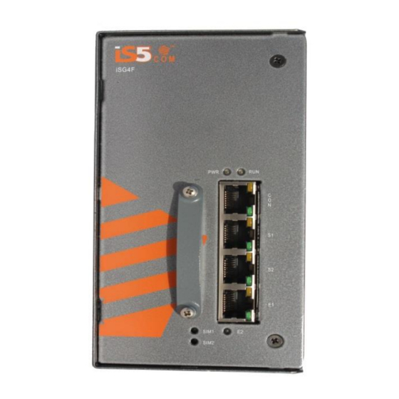
Page 11: Hardware Overview
User’s Manual Storage Temperature: -40 to 85 Operating Humidity: 5% to 95%, non-condensing DIN Rail or Wall mount option Chassis: IP-40 Galvanized Steel Dimensions(W x D x H) : 127 mm(W)x 163.6 mm( D )x 154.2 mm(H) (5 in x 6.44 in x 6.07 in) -
Page 12: Rear
The image below shows the 10 position terminal block and ground lug of the iSG4F. Side view The image below shows the side of the iSG4F with the product label displaying router information. Circled in red are the side mounting holes for the Panel bracket mounting option. -
Page 13: Logical System Diagram
Each router has a DIN-Rail bracket on the rear panel that allows the router to be mounted on a DIN Rail. To mount the iSG4F on a DIN Rail follow the steps below. 1. Slant the top of the router back and hook the top of the DIN bracket onto the top of the DIN rail. -
Page 14: Panel Mounting Option
2. Use the holes in the brackets to secure the router to a wall or panel. Chassis Ground Connection The iSG4F chassis ground connection uses a #6-32 Screw. We recommend terminating the ground connection using a #6 ring lug, and a torque setting of 15 in.lbs (1.7Nm). The red outline indicates the location of the chassis ground. -
Page 15: Power Connections
User’s Manual Power Connections The iSG4F router supports dual redundant power supplies (PWR1 and PWR2). There are 3 options for each power supply: 1. LV: Dual Input 10-48VDC 2. MV: Dual Input 36-75VDC 3. HV: Single Input 85-264VAC or 88-370VDC. -
Page 16: Console Connection
Equipment must be installed according to the applicable country wiring codes. Console Connection To manage the router via the console port, connect the console cable (provided with the iSG4F) from a PC serial port (DB9) to the Console port on the front of the router (RJ45). Configuration... -
Page 17: Supported Functionalities
: use ‘exit’. Configuration ‘interface vlan 1’ To return to the ACE use ‘end’. Supported Functionalities The iSG4F is a feature rich industrial router supporting: L3 dynamic and static Routing SCADA services Firewall Secure networking Supported features include: Ethernet Ports... -
Page 18: System Default State
User’s Manual Vlan Tagging SCADA Gateway Terminal Services IPSec SCADA Firewall Management Authentication Serial Services DHCP Client System Default State The following table details the default state of features and interfaces. Feature Default state Ethernet Ports All ports are enabled... -
Page 19: System Version And Data Base
System Version and Data Base Configuration Database By default User configuration is saved in a file called iSG4F.conf. Configuration saved in this file will be available at system startup. If this file is deleted, the system will boot with the iSG4Fnvram.txt file holding factory configuration. -
Page 20: Os Version
The iSG4F can hold at its disk maximum two OS image files. Before downloading a new OS file to the router make sure the iSG4F has on it only one (the active) file. If needed, delete the unused file before attempting to download new. -
Page 21: Os Upgrade Example
OS Upgrade Example The following flow will show how to upgrade the OS image file and export the data base. 1. Connect your PC via serial console cable to the iSG4F console port. 2. Create an IP interface over eth1. - Page 22 User’s Manual iSG4F# os-image show-list Versions list: IS5_iSG4F_4.0.02.07.tar (active) IS5_iSG4F_4.0.02.06.tar 5. Delete unneeded OS files. iSG4F# os-image delete version-name IS5_iSG4F_4.0.02.06.tar iSG4F# os-image show-list Versions list: IS5_iSG4F_4.0.02.07.tar (active) iSG4F# 6. Download OS file from TFTP server. Command syntax: iSG4F# os-image download download tftp://aa.bb.cc.dd/file_name...
-
Page 23: Safe Mode
1. system reset 2. Loading the factory-default configuration for the device 3. Writing to the EEPROM (should be used only after consulting with iS5 Communications) 4. Recovering the device's images from a package file 5. Export / Import DB (running configuration) 6.5.1 Safe Mode View... - Page 24 User’s Manual ------------------------------------------------------------------------------- ---------- |safe mode menu: reset | 1 : Reset the device format | 2 : Format flash activate | 3 : Activate sw version on flash install | 4 : Install first sw version from TFTP...
-
Page 25: Sw Image Installation
User’s Manual 6.5.2 SW Image Installation The Following steps are for the first software installation. 1. Connect your PC via serial console cable to the iSG4F console port. 2. Reboot the unit and Enter first safe mode. Select option 4. -------------------------------------------------------------------------------... - Page 26 User’s Manual 4. Choose the interface at which the telnet server is connected to the iSG4F. Select Interface (press 1 or 2)[1]: 1) ETH1 10/100 MB 2) ETH2 5. Set the IP address of the TFTP server holding the OS-Image file TFTP SERVER IP ADDRESS [10.10.10.10]: 10.10.10.6...
-
Page 27: Ethernet Port Interfaces
Updating bank1 with vmlinux.UBoot file, please wait ...===OK Version was installed and activated successfully Reboot in 0= Ethernet Port Interfaces The iSG4F hardware includes the following Ethernet interfaces: Gigabit Ethernet, copper RJ45. Copper 10/100/1000 Base T(X) supported. Referred to in CLI as eth1. -
Page 28: Commands Hierarchy
- rmon-etherstat-table port {eth1| eth2} - status + sf-port - ddm - detailed - extended Port Commands Example iSG4F# port show interface-table port eth1 Interface ETH1 +------------------------+--------+-------------------------+-------+ Counter Name | Value | Counter Name | Value | +========================+========+=========================+=======+ | In non-unicast packets | 2670 | Out non-unicast packets |... - Page 29 | 2 | 1 | eth2 | enabled | 100M | full | +-----+------+------+--------------+------------------+-------+------- iSG4F# port show rmon-etherstat-table port eth1 Interface ETH1 +---------------+--------+----------------+-------+ | Counter Name | Value | Counter Name | Value | +===============+========+================+=======+ | total packets | 2789 |...
-
Page 30: Login And Management
User’s Manual jabbers | Size 1024-1518 | 21 +---------------+--------+----------------+-------+ Login and Management Configuring the Login Authentication Method sets the authentication method for user logins. Default user of the system: Name : su Password : 1234 Privileges : all Available by: Console and Telnet. -
Page 31: Cli Terminal Commands
User’s Manual 8.1.2 CLI Terminal Commands Following are commands related to the CLI terminal. + root idle-timeout Management The router can be managed via following methods: IP based Serial console port 8.2.1 Default state Feature Default state Layer 3 interface... -
Page 32: Commands Description
User’s Manual - cancel - show - commit - delete diagnostics - delete logs - delete startup-cfg - show disk info - router interface show - ping <destination> {<user>@<remote IP>} telnet [user]@{remote IP} 8.2.3 Commands Description Command Description Application Connect reload schedule Set specific date and time for router reload. -
Page 33: Ip Interfaces
Cancels all scheduled automatic reloads. reload show Shows user scheduled reloads. IP Interfaces The iSG4F supports multiple layer 3 interfaces to be set for the purposes of: Routing Management Serial services IP Interfaces The following services require assignment of an IP interface:... -
Page 34: Interface Assignment Rules
IP interface set to be in the same subnet as the packets origin (if such is available on the iSG4F). IP interfaces associated to VLANs are given an automatic name indicating the VLAN tag they are created with. -
Page 35: Ip Interface Id
User’s Manual +====+======+=========+===================+======+==================+==============+=============+ | 1 | N/A | eth1:1 | 172.17.203.100/24 | 1500 | application host | enable +----+------+---------+-------------------+------+------------------+--------------+-------------+ | 2 | 20 | eth2.20 | 172.18.212.200/24 | 1500 | general enable +----+------+---------+-------------------+------+------------------+--------------+-------------+ 9.1.2 IP interface id When an IP interface is created without explicitly an assigned VLAN tag, it will not support VLAN tagging. -
Page 36: Ip Interface Commands Description
User’s Manual static {enable | dissable} configure terminal - ip route static <dest network> /<subnet> <Gateway> dhcp {enable | dissable |show} enable physical-interface {eth1| eth2} disable physical-interface {eth1| eth2} show physical-interface {eth1| eth2} interface show route show 9.1.5 IP Interface Commands Description... - Page 37 User’s Manual router interface create address-prefix 10.10.10.100/24 vlan 5 purpose application-host physical-interface eth1 commit commit ok router interface show +----+------+--------+-------------------+------+------------------+--------------+-------- -----+ | Id | VLAN | Name | IP/Subnet | Mtu | Purpose | Admin status | Description |...
- Page 38 User’s Manual iSG4F# iSG4F#router interface create address-prefix 172.17.203.100/24 physical-interface eth2 purpose application-host commit commit ok iSG4F#router interface show +----+------+--------+-------------------+------+------------------+--------------+-------- -----+ | Id | VLAN | Name | IP/Subnet | Mtu | Purpose | Admin status | Description | +====+======+========+===================+======+==================+==============+======== =====+ | 1 | N/A | eth2:1 | 172.17.203.100/24 | 1500 | application host |...
-
Page 39: Dhcp Example
User’s Manual 9.1.7 DHCP Example 1. Enable DHCP on interface eth1 to retrieve an IP from a DHCP server. iSG4F# [/]router dhcp enable physical-interface eth1 [/]router interface show +------+------+-----+-----------+---------+-------------+ | VLAN | Name | Id | IP/Subnet | Purpose | Description |... -
Page 40: Diagnostic
User’s Manual Diagnostic 10.1 System logs export The system logs can be exported to the flash drive as a time conditioned task. 10.1.1 Commands Hierarchy + Root + schedule add task-name copy-logs [day |hour |minute |month |year] remove task-name copy-logs show 10.1.2 Commands Description... -
Page 41: Commands Hierarchy
User’s Manual Captures can be displayed at the terminal or exported to a user TFTP server. 10.2.1 Commands Hierarchy + root + capture - start –i {eth1.<vlan id> | eth1:<id>} [-C] [-s] [-y] [expression <>] - stop - delete - export remote-address <destination address,A.B.C.D>... -
Page 42: Example
User’s Manual 10.2.3 Example 1. Set an IP interface in the ACE for the VLAN. router interface create address-prefix 172.18.212.232/24 vlan 1 purpose application-host physical-interface eth2 commit commit ok router interface show +------+--------+-----+-----------------+------------------+---------- ---+ | VLAN | Name | Id |... -
Page 43: Syslog
User’s Manual 16:55:08.602306 IP 172.18.212.40.17500 > 255.255.255.255.17500: UDP, length 112 16:55:08.604927 IP 172.18.212.40.17500 > 255.255.255.255.17500: UDP, length 112 16:55:08.605016 IP 172.18.212.40.17500 > 172.18.212.255.17500: UDP, length 16:55:08.680664 CDPv2, ttl: 180s, Device-ID 'Router'[|cdp] 10.3 Syslog Configuring Debug Logging determines where the debug logs are to be displayed, that is, either on the console or on a file. -
Page 44: Syslog Commands Hierarchy
User’s Manual Local5 21x8 + level Local6 22x8 + level Local7 23x8 + level Syslog message priority tag with facility local0: Level purpose Numeric level Priority (w. local0) emergencies 16x8+0=128 alerts critical errors warnings notification informational debugging 10.3.2 Syslog Commands Hierarchy... -
Page 45: Alarm Relay
User’s Manual Alarm Relay The router has a capability to manifest system and features alarms as a relay output. 11.1 Alarm Relay Wiring example Below is a connection diagram illustrating the wiring of the alarm relay to warning devices. -
Page 46: Alarm Relay Contact Capabilities
User’s Manual 11.2 Alarm Relay Contact Capabilities Digital outputs are dry mechanical N/O relay contacts. Maximum power to be implemented at the contacts: AC: Max 250v, 37.5vA. DC: Max 220v, 30 watt. The Above mentioned power limitations should not be exceeded. -
Page 47: Commands Description
User’s Manual - remove condition { sfp_eth9| sfp_eth10| temperature| cpu-usage| l2vpn| system-power } - read interface { alarm| d-out1| d-out2} - set interface { alarm| d-out1| d-out2} state { set| clear} + update condition { sfp_eth9| sfp_eth10| temperature| cpu-usage| l2vpn|... -
Page 48: Clock And Time
User’s Manual Command Description Read the current relay state at the interface read interface Alarm – the “ALARM” relay interface. interface : choose a target relay interface to set a static state to (not dependent on a trigger condition) Alarm –... -
Page 49: Local Clock Commands Description
User’s Manual 12.2 Local Clock Commands Description Command Description Config terminal date Sets the current time and date. {[YYYY.]MM.DD-hh:mm[:ss] | hh:mm[:ss]} date Show the system time 12.3 Set Local Clock Example 1. Example for time configuration iSG4F#date 2014.02.02-10:01:30 Sun Feb 2 10:01:30 UTC 2014 Current RTC date/time is 2-2-2014, 10:01:30. -
Page 50: Acl Commands Hierarchy
User’s Manual 13.1 ACL Commands Hierarchy + root ip access-list extended create {acl-num <1001-65535>} [acl-name <>] [redirect <off| on>] delete {acl-num <1001-65535>} permit tcp {acl-num <1001-65535>} [rule-name <>] [priority <1-256>] {src-ip [any| <a.b.c.d>]| <a.b.c.d/e>} {dst-ip [any| <a.b.c.d>]| <a.b.c.d/e>} [src-port <1-65535>]... - Page 51 User’s Manual Command Description configuration mode. Create | delete acl-num <1001-65535>} : the acl main identifier. acl-name: optional name to describe the acl. Redirect: redirect traffic to the SCADA firewall. <off| on> Permit |deny tcp| udp acl-num <1001-65535>} : the acl main identifier.
- Page 52 User’s Manual Command Description Permit |deny icmp acl-num <1001-65535>} : the acl main identifier. rule-name: optional name to describe the rule. Src-ip: Any | <src-ip>| <src-ip/mask>. Source IP address can be: 'any' or the dotted decimal address or the IP address of the host that the packet is from and the network mask to use with the source IP address.
-
Page 53: Configuration Example
[ip/]access-group apply acl-num 1101 interface eth1 direction in priority SCADA services are still commonly using serial legacy hardware. For such applications, the iSG4F supports protocol gateway, serial tunneling and terminal server services. These low bandwidth applications may be of high importance to the utility process and require high network availability. -
Page 54: Nat
Dynamic NAT settings allow LAN members to initiate sessions with targets located at the WAN. The NAT router (iSG4F) will use its WAN IP interface as the new source IP of the session request, hiding the original private IP of the initiating LAN device. The NAT router can use a single WAN IP interface to traverse multiple private IP addresses of its LAN, thus limiting the required public IP addresses to a single one. -
Page 55: Nat Commands Hierarchy
User’s Manual Looking at picture above, PC communication towards the server is dependent on the NAT configuration set on the iSG4F NAT router. Static NAT only The PC will not be able to initiate sessions towards the Server. Sessions initiated by the Server towards the PC will be received by the PC and replies of the PC will be received at the Server. -
Page 56: Nat Commands Description
User’s Manual 15.3 NAT Commands Description Command Description Access the NAT configuration mode Dynamic Create| remove| show interface for dynamic nat. Interface name: the IP interface on which to enable the dynamic NAT. LAN packets egressing the route rover this interface will have their ‘source IP’... - Page 57 4. Set Static NAT settings, directing WAN traffic targeted to 192.168.10.11 with port Telnet (23) towards 10.10.10.10. This will allow the PC to achieve management to the iSG4F. router nat static create original-ip 192.168.10.11 modified-ip 10.10.10.10 original-port 23 modified-port 23 protocol tcp 5.
- Page 58 -------+ [router/]nat dynamic show +---------+---------+-------------+ | Rule-Id | If-Name | Description | +=========+=========+=============+ | eth2:2 | +---------+---------+-------------+ iSG4F#router nat static show +---------+-----------------+-------------------+----------+-----------------+------------- ------+ | Rule-Id | Original-Dst-IP | Original-Dst-Port | Protocol | Modified-Dst-IP | Modified-Dst-Port +=========+=================+===================+==========+=================+============= ======+ | 192.168.10.11 | 10.10.10.10...
-
Page 59: Ospf
User’s Manual OSPF OSPF (Open Shortest Path First) protocol is an Interior Gateway Protocol used to distribute routing information within a single Autonomous System. Routers use link-state algorithms to send routing information to all nodes in an inter-network by calculating the shortest path to each node based on topography of the Internet constructed by each node. -
Page 60: Ospf Setup Example
User’s Manual Command Description router interface Add or Remove an IP interface for the application engine. The configuration create | remove should include: Address-prefix : IP address in the format aa.bb.cc.dd/xx VLAN : vlan ID that the application engine will use for this IP interface ... - Page 61 User’s Manual S1 configuration 1. Remove network ports from default VLAN 1 config vlan 1 no ports fa 0/1-2 untagged fa 0/1-2 exit 2. Assign VLANS and corresponding IP interfaces vlan 101 ports fastethernet 0/1 exit vlan 102 ports fastethernet 0/2...
- Page 62 User’s Manual exit interface vlan 102 shutdown ip address 172.18.102.201 255.255.255.0 no shutdown exit 3. Configure OSPF router ospf router-id 10.10.10.101 network 172.18.101.201 255.255.255.0 area 0.0.0.0 network 172.18.102.201 255.255.255.0 area 0.0.0.0 commit iS5 Communications Inc.
- Page 63 User’s Manual S2 configuration 1. Remove network ports from default VLAN config vlan 1 no ports fa 0/2,0/3 untagged fa 0/2-3 exit 2. Assign VLANS and corresponding IP interfaces vlan 102 ports fastethernet 0/2 exit vlan 103 ports fastethernet 0/3...
- Page 64 User’s Manual commit S3 configuration 1. Remove network ports from default VLAN 1 config vlan 1 no ports fa 0/4,0/3 untagged fa 0/3-4 exit 2. Assign VLANs and corresponding IP interfaces vlan 103 ports fastethernet 0/3 exit vlan 104...
- Page 65 User’s Manual commit S4 configuration 1. Remove network ports from default VLAN 1 config vlan 1 no ports fa 0/4,0/1 untagged fa 0/1,0/4 exit 2. Assign VLANs and corresponding IP interfaces vlan 101 ports fastethernet 0/1 exit vlan 104...
-
Page 66: Ripv2
User’s Manual network 172.18.104.204 255.255.255.0 area 0.0.0.0 network 172.18.101.204 255.255.255.0 area 0.0.0.0 commit RIPv2 RIP (Routing Information Protocol), is a distance-vector routing protocol, which employs the hop count as a routing metric. 17.1 RIP Commands Hierarchy +root router rip... -
Page 67: Rip Commands Descriptions
User’s Manual 17.2 RIP Commands Descriptions Command Description router interface Add or Remove an IP interface for the application engine. The configuration should include: create | remove Address-prefix : IP address in the format aa.bb.cc.dd/xx VLAN : vlan ID that the application engine will use for this IP interface ... -
Page 68: Serial Ports And Services
User’s Manual Command Description Interface <IFNAME> Enter the interface level. IFNAME can be for example eth1.x whereas x is the vlan identifier. Set a RIP enabled interface by ifname. Both the sending and receiving of RIP packets will be enabled on the port specified in the network ifname command. -
Page 69: Serial Interfaces
1. Transparent tunneling 2. Terminal Server 3. Protocol Gateway 18.1 Serial interfaces Two serial interfaces are available at the iSG4F. 18.2 Services configuration structure The table below contains the relevant configuration areas which should be included per application type. 101/104... -
Page 70: Serial Commands Hierarchy
User’s Manual Bus-idle-time Parity Dtr-dsr Rts-cts Local-dsr-delay Local-cts-delay 18.3 Serial Commands Hierarchy serial Service show serial local-end-point filter show card auto-recover {enable |disable |show} show port clear counters create [slot <1>] {port <1-2>} [baudrate <9600,(50-368400)>] [parity <no,(no| odd| even)>] [stopbits <1,1|2>][bus-idle-time... -
Page 71: Serial Commands Description
User’s Manual [iec101-link-address <0-65535>] [iec101-link-address-len (2,<1|2>] [iec101-originator-address {none| present}] [unit-id-len (2,<1|2>] [unit-id <0-65535>] remove [slot <1>] {port <1-2>} {service-id <1-100>} show remote-end-point create {remote-address <A.B.C.D>} {service-id <1-100>} {position <master| slave>} [connection-mode [<udp| tcp>] [buffer-mode {byte| frame}] remove {remote-address < A.B.C.D>} {service-id <1-100>}... - Page 72 User’s Manual Command Description Create Slot : 1 (constant) Port : port number .1-2 update Baud rate : 50,75,100,110,134,150,200,300, 600,1200,2400,4800,9600,19200, 38400,57600,115200,230400, 460800,921600 Parity : no, odd, even Stopbits : 1,2 admin-status: up| done. Default= up. Mode of operation: transparent...
- Page 73 User’s Manual Command Description Create Slot : 1 (constant) Port : port number .1-2 Service id: numeric value of serial service. Position: Master – point to multipoint Slave – point to multipoint Application : Serial-tunnel (default) Terminal-server iec101-gw modbus-gw...
-
Page 74: Declaration Of Ports
User’s Manual Command Description Remove Slot : 1 (constant) Port : port number .1-2 Service id: numeric value of serial service. Position: Master – point to multipoint Slave – point to multipoint Application : Serial-tunnel (default) Terminal-server iec101-gw modbus-gw... -
Page 75: Serial Port Default State
The default state of the serial ports is non-configured. 18.7 RS- 232 Port Pin Assignment Below is the pin assignment of the serial ports. iSG4F Serial RJ45 Female Port Line NOTE The serial control lines are not supported at current version... -
Page 76: Serial Cable
User’s Manual 18.8 RS- 232 Serial cable The RS-232 ports are of RJ-45 type, a cable is available as an ordering option having one end of male RJ-45 and second end of female DB-9. The cable should be used when no control lines are needed. -
Page 77: Transparent Serial Tunneling
The UDP|TCP packet is sourced with a local IP interface. Topologies supported are P2P, P2MP and MP2MP over a single unit or IP network. The condition for transparent serial tunneling is having an iS5 router/ router at both ends of the network, connecting the devices. -
Page 78: Supported Network Topologies
User’s Manual 19.2 Supported Network Topologies Transparent serial tunneling supports following topologies: 1. Point to point 2. Point to multipoint point 3. Multi Point to multipoint point 19.2.1 Point to Point The picture below illustrates Point-to-point service at which the master and slave are connected locally at the same router. -
Page 79: Multi Point To Multipoint Point
User’s Manual 19.2.3 Multi Point to multipoint point The picture below illustrates a typical multipoint-to-multipoint service. 19.3 Modes of Operation iS5 Communications Inc. -
Page 80: Port Mode
User’s Manual 19.3.1 Port Mode The port mode-of-operation is set at the serial port configuration level and defines how serial data is collected. Transparent Tunneling Transparent-tunneling is a mode at which serial data is sent with a distinct start bit, stop bit and a known length of data bits. -
Page 81: Service Connection Mode
User’s Manual 19.3.3 Service Connection Mode The service connection-mode is set at remote-end-point configuration level and defines the protocol option to be used for the service-id. Serial data will be encapsulated as UDP/IP frames. This is the default option for a serial service. -
Page 82: Reference Drawing
For ease of explanation of following terms and serial properties at this chapter, the diagram below will be used as a reference to follow on the serial traffic flow. The diagram demonstrates two iSG4F routers connected over an Ethernet network and sharing a transparent serial tunneling service. -
Page 83: Serial Traffic Direction
User’s Manual The customer equipment #1 (CE1) is a serial master sending data to a serial slave CE2. For simplicity purposes, the diagram and explanations refer to unidirectional traffic from CE1 to CE2. 19.6 Serial Traffic Direction Transmit direction represents the serial-processor traffic towards the CE, over the serial port. -
Page 84: Allowed Latency
User’s Manual 19.7 Allowed Latency Allowed latency is the maximum time allowed for the serial-processor to collect serial data from CE1 transmission, before closing an Ethernet packet and sending it over the cloud. This parameter refers to round-trip in milliseconds units. It reflects only the time for the serial processor to collect data, it does not consider the network self-latency. -
Page 85: Example Serial Tunneling
User’s Manual 19.10 Example Serial Tunneling The network below demonstrates a P2P topology of transparent serial tunneling. Configuration router A (MASTER) 1. configure the gateway (values are example only) router interface create address-prefix 172.18.212.231/24 vlan 100 purpose application-host physical-interface eth2... -
Page 86: Protocol Gateway Iec 101 To Iec 104
Protocol Gateway IEC 101 to IEC 104 The iSG4F router, using its application module implements the gateway for IEC101 serial devices to the IEC104 IP protocol. The IEC101 and IEC104 protocols are fully integrated in the application module thus allowing the IEC101 slave devices to be represented as a IEC104 server in the IP network and to be addressed as such by IEC104 clients located anywhere in iS5 Communications Inc. -
Page 87: Modes Of Operation
User’s Manual the network. The gateway implementation consists of 3 functions: IEC104 Server – The application module will act as a IEC104 server to any IEC104 clients that connect to it over the Ethernet network. This function includes the full implementation of the state-machine of the IEC104 server, response to keep-alive test frames and listening of TCP port 2404 for any client requests. -
Page 88: Iec101/104 Gateway Properties Iec 101
User’s Manual 20.2 IEC101/104 Gateway properties IEC 101 System role : Controlling station definition (Master) Network configuration : Point-to-point Multiple point-to-point Multipoint-party line (planned) Physical layer Transmission speed in monitor & control direction: 300 – 38400bps ... -
Page 89: Iec101/104 Gateway Configuration
User’s Manual Three octets Structured Unstructured Cause of transmission One octet Two octets (with originator address) 20.3 IEC101/104 Gateway Configuration The IEC101/104 gateway can be configured through the systems CLI or as part of an IEC104 network-wide service-group in the iNMS (industrial network management system) tool. -
Page 90: Gateway 101/104 Configuration Flow
Set static or dynamic routing if needed to reach the IEC 104 Client. d. Verify by following methods i. Successful ping between the IEC 104 Client (SCADA) and the iSG4F designated IP interface. ii. IEC 104 connection established. Use the command “iec101-gw show all”... - Page 91 User’s Manual i. Create a local-end-point and assign the serial port. ii. The local-end-point field ‘application’ must be set to ‘iec101-gw’ Enable the gateway i. Assign the gateway to use the predefined ACE interface. ii. Set the desired mode ‘balanced’ or ‘unbalanced’.
-
Page 92: Gateway 101/104 Commands Hierarchy
User’s Manual iv. Verify the IEC properties are consistent between the gateway and the RTU (CA, LA, CA length, LA length, COT) 20.5 Gateway 101/104 Commands Hierarchy + root serial port clear counters create {slot <1>} {port <1-2>} {mode-of-operation <... -
Page 93: Gateway 101/104 Commands
User’s Manual [dir_bit<AUTO,(AUTO|0|1)>] [single_char <y,(n|y)>] [test_proc <y,(n|y)>] [gen_inter <n,(n|y)>] [time_tag <n,(n|y)>] iec101 remove [slot <1>] {port <1-2>} iec101 [add_asdu | remove_asdu] port <1-2> {asdu_addr {(1-255)| (1-65534)}} {link address {(1-255)| (1-65534)}} iec101 [add_ioa_trans>| remove_ioa_trans] port <1-2> src_ioa {a1-a2-a3| a1-a2| a}... - Page 94 User’s Manual Command Description remove asdu_addr : Common Address of ASDU. Usually Should be configured as the ASDU address of the IEC101 Server unless a translation service is required. In the latter case, should be configured as the address which is set at the 104 Client for the server.
- Page 95 User’s Manual Command Description orig_addr: Should be configured as the Originator address set at the 101 slave. orig_addr_participate: y|n to indicate if the 101 slave uses the originator address field. Should be identical to the configuration at the 101 slave.
-
Page 96: Example Gateway 101/104
: Time-out for acknowledges in case of no data messages t2 < t1 t3: Time-out for sending test frames in case of a long idle state 20.7 Example Gateway 101/104 The network below demonstrates an IEC 101/104 setup using the iSG4F as a gateway. iS5 Communications Inc. - Page 97 User’s Manual Configuration Configure an IP interface for the gateway. iSG4F#router interface create address-prefix 192.168.10.11/24 physical-interface eth1 description Network purpose application-host Configure the serial port properties. Field ‘mode-of-operation must be set to ‘transparent’. The port properties must be in-line with the IEC 101 server device connected (same baud rate, parity, stop bits, data bits and such).
-
Page 98: Terminal Server
User’s Manual Terminal Server 21.1 Terminal Server service iS5 routers allows a special service for transposing of a TCP session to serial session. Networking: A router acting as the terminal server can be connected to the Ethernet telnet client (management station) via: ... - Page 99 In bellow example Serial transparent tunneling (UDP|TCP traffic) will take place between the iS5 routers thus establishing the paths from the serial RTUs to router A . Using the mapping between the telnet sessions and the serial services the application will direct the traffic from the management station to the RTUs allowing each its own path for management.
-
Page 100: Terminal Server Commands Hierarchy
User’s Manual 21.2 Terminal Server Commands Hierarchy root serial port clear counters create slot <1> port <1-2> [baudrate <9600,(50-368400)>] databits {8,<5-8>} [parity {no,no| odd| even}] [stopbits <1,1|2>] [bus-idle-time <bits (30-1000>] [mode-of-operation <transparent>] admin-status [up| down] remove slot <1> port <1-2>... -
Page 101: Terminal Server Commands
User’s Manual connections disconnect connections dissconnect service-id <> show service-id <> counters [clear | show] settings restore update [low-border-telnet-port <>] [dead-peer-timeout <0-1440>] [buffer-mode <frame |byte>] show telnet-service create remote-address <A.B.C.D> service-id <1-100> telnet-port <range> null-cr-mode {off,<off|on>} max-tcp-clients <1-8> remove service-id <1-100>... - Page 102 User’s Manual Command Description Create Slot : 1 (constant) Port : port number .1-4 Baud rate : 50,75,100,110,134,150,200,300, 600,1200,2400,4800,9600,19200, 38400,57600,115200,230400, 460800,921600 Parity : no, odd, even Stopbits : 1,2 Mode of operation : transparent Remove Slot : 1 (constant) Port : port number .1-4...
- Page 103 User’s Manual Command Description Connections Manage the TCP connections to the terminal server [disconnect | show] service-id : serial service-id number assigned to the terminal server counters Display counters iS5 Communications Inc.
- Page 104 User’s Manual Command Description settings Manage the range of TCP ports used for the terminal server to respond to. By default the allowed range is 2001-2100. Restore: restore to the default range. Update low-border-telnet-port <>: a numeric value for the TCP port range low border.
- Page 105 User’s Manual Command Description Serial-tunnel Configuration options to be used at the router where the serial port is connected at. These fields will determine the remote side to where to draw the serial service to (the remote side is the router at which the terminal server is established).
- Page 106 User’s Manual Command Description telnet-service Configuration options to be used at the router where the terminal server is set. These fields will determine the remote side to where to draw the serial service to (the remote side is the router at which the serial device is connected at).
-
Page 107: Example Local Service
User’s Manual Command Description remove Address: IP address in the form of aa.bb.cc.dd. The IP is of the Application interface at the router at which the serial port is connected at. Telnet-port: TCP port number in the range of 2000-2100. - Page 108 1 remote-address 172.18.212.230 telnet-port 20000 commit NOTE Make sure to use proper serial connection between the iSG4F serial port and the customer equipment. The pin-out of the iSG4f serial port is given in this documentation. iS5 Communications Inc.
- Page 109 User’s Manual Testing the setup Review your configuration using the following show commands: router interface show iSG4F# +------+---------+----+----------------+------------------+----------- | VLAN | Name | Id | IP/Subnet Purpose | Description | +======+=========+====+================+==================+=========== | N/A | eth1:1 | 1 |172.18.212.230/24|application host |...
- Page 110 | 172.18.212.230 | +-------+------------+-------------+----------------+ Ping between the PC (172.18.212.240) and the iSG4F (172.18.212.230) to validate IP connectivity. Open a telnet session from the PC to the router “telnet 172.18.212.230 20000". The connection will be indicated in the following show output.
-
Page 111: Example Networking
Your serial device shell will be reachable to telnet client (PC). The serial connection can be validated by following the port counters. iSG4F#serial port show briefly slot 1 port 1 +-----+------+------+-----+-------------+------+------+--------+------ | idx | slot | port | svc |... - Page 112 User’s Manual Assign an IP interface. The mode of operation of the serial port must be “transparent” The local end point application type must be “terminal server”. router interface create address-prefix 172.18.212.230/24 vlan 100 purpose application-host physical-interface eth2 serial port create slot 1 port 1 mode-of-operation transparent...
-
Page 113: Modbus Gateway
User’s Manual Modbus Gateway The iS5 capability of gateway Modbus RTU to Modbus TCP is of yet another benefit to industrial area applications. The router allows connecting an RS232 Modbus RTU and gateway it to a remote Modbus TCP client (SCADA) over the Ethernet. - Page 114 User’s Manual local-end-point create create {slot <1>} {port <1-4>} {application < modbus-gw >}{service-id <>} [position <>] [protocol <>] show modbus-gw show-gw-list connection [clear | show] counters - clear-id {gw-id <1-5>} {unit-id <1-255>} - clear-port {slot 1 port <1-4>} - show-by-id gw-id <1-5>}...
-
Page 115: Modbus Gateway Commands Description
User’s Manual 22.3 Modbus Gateway Commands Description Command Description modbus-gw show-gw-list Display the list of available gateway Connection Clear| show live and history TCP connections counters Clear| show counters per gateway id and unit id debug map-units-on-bus-start: initiate mapping of connected station ids behind a serial port. -
Page 116: Modbus Gateway Example
User’s Manual Command Description show-ids Show Modbus RTU station ids behind a gateway instance. update Update a gateway instance properties. admin-status (enable| disable) timeout-period <500-100,000> 22.4 Modbus Gateway Example The Following setup demonstrates Modbus gateway configuration. 1. Assign IP interface for the gateway. - Page 117 User’s Manual output example [/] modbus-gw connection show +-------+-------+-------------------+----------------+----------+ | Index | GW id | GW IP/Subnet ip addr | src port | +=======+=======+===================+================+==========+ | 192.168.40.11/24 | 192.168.40.11 | 55132 +-------+-------+-------------------+----------------+----------+ Completed OK [modbus-gw/] debug map-units-on-bus-start port 1 slot 1...
- Page 118 User’s Manual +------+------+----------+----------+----------+----------+ [modbus-gw/] debug map-units-on-bus-show Operation in process [modbus-gw/] history show gw-id 4 Units connected to Gw 4: +----+-----------------+ | id | seconds elapsed | +====+=================+ | 3 | [modbus-gw/] mapping show-ids +----------+------------------+---------+------+------+-------+ | GW index | GW IP/Subnet...
-
Page 119: Dnp3 Gateway
DNP3 Gateway DNP3 (Distributed Network Protocol) is an important protocol set used at SCADA applications. The iS5 switch supports gateway functionality between a DNP3 TCP client (master) and a DNP3 Serial RTU. Configuration of a DNP3 gateway is made using the terminal server feature with the protocol well known TCP port 20000. -
Page 120: Vpn
The iS5 routers support such a VPN (Virtual Private Network) connection using GRE tunnels (RFC2 2784) over an IPSec encrypted link. The IPSec tunnel can use 3DES or AES encryption according to the user configuration. -
Page 121: Layer 3 Dm-Vpn
User’s Manual 3. Single tunnel allowed at each spoke towards the Hub. 4. L2 VPN is supported over fixed uplink and as well over cellular. 5. Based on MAC learning 6. Layer 2 protection protocols as G.8032 and RSTP are supported to allow protection between a VPN uplink and a second uplink. -
Page 122: L2-Vpn Commands
User’s Manual - parameters [icmp-send-fragmentation-needed <enabled| disabled>] [spanning-tree-mode [normal| transparent>] nhrp hub show spoke {[update {private-ip <>} {remote-ip <>}] | [show]} show clear 24.6 L2-VPN Commands Command Description L2-vpn Enter the tunnel configuration nhrp For cellular application only Hub show... -
Page 123: L3 Ipsec-Vpn Commands Hierarchy
User’s Manual vpn gre tunnel create {name <>} {address-prefix <A.B.C.D/M>} {lower-layer-dev <ETH1.<vlan id> >} {key(0.0.0.0,<a.b.c.d>)} [ttl (64,<0-255>)] [holding-time<7200,1-65535>] [cisco-authentication <>] (1418,<128-9600>) (inherint,<0-255>) [tunnel-destination <>][tunnel-source <>] remove {name<>} show [name<>] nhrp {craete | update} {multipoint-gre-name<>} {nbma-address<>} {protocol-address-prefix< A.B.C.D/M>} [initial-register<no|yes>] [is-cisco<no|yes>] [protection-group<>] [position<master |slave>]... -
Page 124: Ipsec
User’s Manual crate {name <>} {address-prefix <A.B.C.D/M>} {lower-layer-dev <ETH1.<vlan id> >} {remote-address<A.B.C.D>} [mtu<1400,128-1500>][ttl <64,0-255>] remove {name<>} <>] show name 24.9 IPSec Internet Protocol Security (IPsec) is a protocol suite for securing Internet Protocol (IP) communications by authenticating and/or encrypting each IP packet of a communication session. -
Page 125: Isakmp
User’s Manual entities. ISAKMP provides the protocol exchanges to establish a security association between negotiating entities followed by the establishment of a security association by these negotiating entities in behalf of ESP/AH. 24.14 ISAKMP ISAKMP provides a framework for agreeing to the format of SA attributes, and for negotiating, modifying, and deleting SAs. - Page 126 User’s Manual may then be converted into cryptographic keying material for other (symmetric) algorithms. Diffie-Hellman key agreement requires that both the sender and recipient of a message have key pairs. The private key of each member is never sent over the insecure channel.
- Page 127 User’s Manual iSG4F# ipsec isakmp update authentication-method pre_shared_key ipsec isakmp update my-id SA.iS5com.com ipsec preshared create id SA.iS5com.com key secretkey ipsec preshared create id SB.iS5com.com key secretkey ipsec policy create protocol gre ipsec enable commit iS5 Communications Inc.
- Page 128 User’s Manual The above configuration example will result in following show output. iS5 Communications Inc.
- Page 129 Below is a screenshot of such 2 files placed on a PC with tftp client and CLI example of importing them. Figure 1 The certificate files 1. Import the key file. iSG4F# rsA-signature import tftp://172.17.203.31/ipsec.key RSA signature file (ipsec.key) imported successfully 2. Import the certificate file. iSG4F# rsA-signature import tftp://172.17.203.31/ipsec.crt RSA signature file (ipsec.crt) imported successfully...
- Page 130 User’s Manual The above configuration example will result in following show output. Exchange Modes Main Main mode is the more secure option for phase1 as it involves the identity protection. Session flow: Session begins with the initiator sending a proposal to the responder describing what encryption and authentication protocols are supported, the life time of the keys, and if phase 2 perfect forward secrecy should be implemented.
- Page 131 User’s Manual IPSec negotiation (Quick Mode) begins. In applications at which the IP addresses used for the VPN network are not static (for example a cellular spoke retrieving dynamic IP from the ISP over its PPP interface) the Main mode of IKE is not applicable.
-
Page 132: Isakmp Phase 2
Modes The common mode to use between end stations supporting IPSec (the VPN parties) is called Transport mode. This is the mode supported by iS5. Perfect forward secrecy (PFS) The PFS is a part of the key agreement session and has a purpose to ensure that a session key derived from a set of long-term public and private keys will not be compromised if one of the (long-term) private keys is compromised in the future. -
Page 133: Ipsec Command Association
User’s Manual Supported mode Transport (yes) Tunnel (no) Authentication s HASH algorithms Secure Hash Algorithm SHA-1 (160 bit) Secure Hash Algorithm SHA-2 (256 |512 bit) Message Digest (MD5) (128 bit) Perfect Forward Secrecy type (PFS) ... -
Page 134: Ipsec Commands Hierarchy
User’s Manual id-type (id-type) soft timer (soft-lifetime) Phase 1 Authentication method {pre_shared_key | rsasig} Diffie–Hellman key exchange Group (dh-group) Internet Key Exchange mode (ike-phase1-mode) Encryption Algorithm (phase1-encryption-algo) Hash Algorithm (phase1-hash-algo) Life Time (phase1-lifetime) Phase 2 Perfect Forward Secrecy (pfs-group) - Page 135 User’s Manual rsA-signature import {flash:<file name> | sftp://<user:password@<ip>/<file_name> | tftp://<ip>/<file_name> } show rsA-signature list ipsec {enable | disable} flush-sa proto {ah | esp | ipsec | isakmp} rsa-signature activate {crt-file <file name> | key-file <file name> |rsa-sig-name <name>} isakmp update...
-
Page 136: Ipsec Commands
User’s Manual preshared {create | remove} <> <> log-show {grep | num-of-lines } - show - show-sa proto {ah | esp | ipsec | isakmp} 24.18 IPsec Commands Command Description rsA-signature import Import the X.509 certificate file and key file to the application from a connected USB drive or tftp /sftp servers. - Page 137 User’s Manual Command Description the key exchange process. The higher the group number, the stronger the key and security increases. Options : none modp768 (DH group 1) modp1024 (default) (DH group 2) modp1536 (DH group 3 and 5) modp2048 (DH group 14)
- Page 138 User’s Manual Command Description interval between following keep alive messages. Permissible range : 0-120 (default is 5) dpd-maxfail Dead Peer Discovery max attempts to determine failure. Permissible range :2-20 (default is 5) dpd-retry Dead Peer Discovery max retry attempts. A retry is initiated after a failure at “dpd-maxfail”.
- Page 139 User’s Manual Command Description None: the units own preshared id will be the default ip interface. Address: this option is not supported in current version. fqdn: the units own preshared id will be in a domain name format. For example spoke.iS5com.com...
- Page 140 User’s Manual Command Description Encryption Algorithm for phase 2. phase2-encryption-algo 3des (default) aes-128 aes-256 Phase2-lifetime The lifetime of the key generated between the stations. 180-946080000 sec. Default is 86400 soft-lifetime When a dynamic IPSec SA is created, two types of lifetimes are used: hard and soft.
- Page 141 User’s Manual Command Description protocol: the type of protocol ,for example TCP ,UDP,GRE. Preshared Configuration of pre shared identifiers {create | remove} for local node and all remote IPsec nodes. ID: unique identifier for the IPSec participant node can be in either domain name format or ipv4 format.)
-
Page 142: Ipsec Defaults
GPRS/UMTS Interface 25.1 Overview An important benefit of the iS5 portfolio is its support of variety of medium interfaces. A GPRS/UMTS modem provides a key solution for connectivity to remote sites. The modem support dual SIM card for redundancy and backup between Internet Service Providers. -
Page 143: Method Of Operation
IP from the ISP. 25.2 Method of operation At the iSG4F spoke side, a simple configuration of the cellular modem is enough to have the spoke approach the ISP to retrieve an IP address using known link protocol PPP. -
Page 144: Sim Card State
User’s Manual STATIC IP assigned to it. The Hub will listen on its interface to NHRP requests from the spoke and will allow the VPN establishment dependent on the authentication. A Hub must have a fixed connection to the network. It may not be connected with the cellular modem as a spoke. - Page 145 User’s Manual Ready – SIM is available and configured. Connecting – Modem is trying to retrieve IP from the ISP using the SIM Connected – the modem retrieved an IP address from the ISP with the selected SIM.
-
Page 146: Backup And Redundancy
User’s Manual 1. The modem retrieved an IP from the ISP 25.2.2 Backup and redundancy Backup between Interfaces (between GSM or Physical interface) A GSM link is by nature a high cost path and with a significant lower bandwidth then a physical channel. -
Page 147: Gprs/Umts Commands Hierarchy
User’s Manual reached “FAILED”. Such attempt is approximately 2 minutes long (nonconfigurable). The counter progresses with every such above condition and summarize for both Sims together. The following states will reset the counter: “CONNECTED”, “CONNECTED AS ALTERNATIVE”,”CONNECTED AS SECONDARY”. -
Page 148: Gprs/Umts Commands Description
User’s Manual <pin>] [user-name <name>] [password <password>] [radio-access-technology {auto |2G |3G |2Gthen3G |3Gthen2G}] [flow-control {enable | disable}] show refresh network {show} Connection {show} enable disable show nhrp {show} spoke update private-ip A.B.C.D remote-ip A.B.C.D show 25.4 GPRS/UMTS Commands Description... - Page 149 User’s Manual Command Description Create | name: name of the test (text) update dest-ip-address: ip address of a reachable (routable) host. Format aa.bb.cc.dd rtt-threshold: round trip threshold in msec. <1,000-20,000> loss-threshold: calculated percentage of icmp requests which were not responded.
- Page 150 User’s Manual Command Description Settings update quality check: define time interval in seconds for internal RSSI check of active SIM.<0-604800>. 0 –disable RSSI check. backoff1: minimum time to stay on a SIM after any fail over. < sec,10-600> backoff2: minimum time to stay on a SIM if “caveat”...
- Page 151 User’s Manual Command Description Settings show Show: show configured interval time. Wan update Sim-slot: location of SIM to be configured, 1 or 2. Admin-status: enable/disable SIM card. Apn-name: as given by the network provider. operator-name : operator name (text) Pin: as given by the network provider.
-
Page 152: Default State
User’s Manual 25.5 Default State The default state of the cellular modem is “disabled”. The settings default state is as shown in below table. 25.6 Led States The modem has a led indicator for each SIM slot to represent the SIM cad state. -
Page 153: Example For Sim Status
User’s Manual 25.8 Example for SIM Status Below is a configuration example of 2 SIM cards and their permissible state status. cellular wan update admin-status enable apn-name internetg sim-slot 1 operator-name cellcom user-name guest password guest cellular wan update admin-status enable apn-name internet.pelephone.net.il... -
Page 154: Vpn Setup Examples
26.1.1 Network drawing 26.1.2 Configuration ROUTER C - ROUTER 1. Create IP Interfaces: iSG4F# router interface create address-prefix 172.17.203.100/24 vlan 17 purpose application-host physical-interface eth1 iSG4F# router interface create address-prefix 172.18.212.100/24 vlan 18 purpose general physical-interface eth2 iS5 Communications Inc. - Page 155 User’s Manual ROUTER A (iSG18FGP) 1. Create vlan for network port: config vlan 17 ports fastethernet 0/1 gigabitethernet 0/3 exit 2. Create vlan access for user port: vlan 10 ports fastethernet 0/2 gigabitethernet 0/4 untagged fastethernet 0/2 exit interface fastethernet 0/2...
- Page 156 192.168.0.101 255.255.255.0 no shutdown exit ROUTER B (iSG4F) 1. Create IP Interfaces. iSG4F# router interface create address-prefix 172.18.212.220/24 vlan 18 purpose application-host physical-interface eth1 iSG4F#router interface create address-prefix 192.168.0.102/24 physical-interface eth2 purpose general Commit 2. Configure the route over the router.
-
Page 157: Implementing Ipsec
User’s Manual Test Ping is now possible between : The application IPs : 172.17.203.220 and 172.18.212.220 The PCs : 192.168.0.100 and 192.168.0.101. 26.1.3 Implementing IPSec ROUTER A 1. Configure IPSec: iSG18GFP#application connect ipsec isakmp update my-id SA.iS5com.com ipsec preshared create id SA.iS5com.com key secretkey... -
Page 158: Network Drawing
The Routers are configured so that the computers can remote manage them via SSH through the tunnel. 26.2.1 Network drawing 26.2.2 Configuration ROUTER (iSG4F router) 1. Create IP Interfaces: iSG4F#router interface create address-prefix 172.18.30.100/24 vlan 30 purpose application-host physical-interface eth2 commit iSG4F#router interface create address-prefix 172.18.20.100/24 vlan 20 purpose general physical-interface eth1 commit 1. - Page 159 User’s Manual vlan 1 no ports fastethernet 0/1,0/4 gigabitethernet 0/3 untagged fastethernet 0/1,0/4 exit 3. Assign the user and network vlans and set PVID for the untagged ports. vlan 10 ports fastethernet 0/1 gigabitethernet 0/3 untagged fastethernet 0/1 exit...
- Page 160 User’s Manual router interface create address-prefix 192.168.10.1/24 vlan 10 purpose application-host description user1 7. Assign IP interface in the application towards the WAN router. router interface create address-prefix 172.18.20.10/24 vlan 20 purpose general description wan 8. Assign the IPSec tunnel.
- Page 161 User’s Manual exit commit iS5 Communications Inc.
- Page 162 User’s Manual SPOKE 1. Assign the user and network vlans and set PVID for the untagged ports. iSG4F#router interface create address-prefix 172.18.30.20/24 vlan 30 purpose application-host physical-interface eth2 commit iSG4F#router interface create address-prefix 192.168.40.1/24 physical-interface eth1 purpose general commit 2.
-
Page 163: Dm-Vpn Setup
User’s Manual ipsec preshared create id 172.18.30.20 key 123456 !local public ip eth1.30 ipsec policy create protocol ipencap ipsec enable commit exit commit Test Ping is now possible between : The application IPs : 172.18.20.10 and 172.18.30.20 ... -
Page 164: Configuration
User’s Manual 26.3.2 Configuration HUB (iSG18GFP) 1. Set router host name (not mandatory). set host-name hub 2. Disable spanning tree and remove the ports to be used in the VPN from default vlan 1. config terminal no spanning-tree vlan 1... - Page 165 User’s Manual shut ip address 192.168.10.1 255.255.255.0 no shut exit 5. Assign static route so router management will be routable over the VPN. ip route 0.0.0.0 0.0.0.0 192.168.10.10 1 commit 6. Assign ACE IP interface which will route user traffic.
- Page 166 User’s Manual ipsec isakmp update id-type fqdn ipsec policy create protocol gre ipsec disable ipsec enable commit exit write startup-cfg SPOKE (iSG4F) 1. Assign IP interface to route user traffic. router interface create address-prefix 192.168.40.10/24 physical-interface eth1 description UNI purpose general admin-status enable 2.
-
Page 167: Dm-Vpn Over Cellular Setup
User’s Manual 5. Configure IPSec. ipsec isakmp update my-id RTU1.iS5com.com ipsec preshared create id HUB.iS5com.com key secretkey ipsec preshared create id RTU1.iS5com.com key secretkey ipsec isakmp update id-type fqdn ipsec policy create protocol gre ipsec disable ipsec enable commit... -
Page 168: Network Drawing
SCADA (connected via its com port to the router RS-232 port 1 at the hub) and the serial device connected at the spoke (RS-232 port 2). 26.4.1 Network drawing Figure 2 : L3 VPN , cellular spoke – iSG4F hub iS5 Communications Inc. -
Page 169: Configuration
User’s Manual 26.4.2 Configuration Spoke 1. Create an interface to route the lan traffic coming to port eth1. iSG4F# router interface create address-prefix 192.168.40.10/24 physical-interface eth1 description UNI purpose application-host admin-status enable 2. Enable cellular application mode. cellular enable cellular settings update default-route yes 3. - Page 170 User’s Manual commit 7. IPSec configuration. iSG4F# ipsec isakmp update my-id RTU1.iS5com.com ipsec preshared create id HUB.iS5com.com key secretkey ipsec preshared create id RTU1.iS5com.com key secretkey ipsec isakmp update id-type fqdn ipsec policy create protocol gre ipsec enable commit exit 1.
- Page 171 User’s Manual exit interface vlan 10 shutdown ip address 192.168.10.1 255.255.255.0 no shut exit ip route 0.0.0.0 0.0.0.0 192.168.10.10 1 commit 2. Create an IP interface ETH.20 in the subnet of the router. router interface create address-prefix 172.18.212.230/24 vlan 20 purpose...
-
Page 172: Testing The Setup
User’s Manual ip route 192.168.40.0/24 10.10.10.20 ip route 0.0.0.0/0 172.18.212.100 write exit exit 7. IPSec configuration. iSG4F#application connect ipsec isakmp update my-id PC.iS5com.com ipsec preshared create id PC.iS5com.com key secretkey ipsec preshared create id RTU1.iS5com.com key secretkey ipsec isakmp update id-type fqdn... - Page 173 User’s Manual Ping 'public ip of the spoke'. Ping 80.74.102.38. 3. Send traffic between the 2 PCs. Show example at the spoke iSG4F#router interface show +----+------+--------+------------------+------+------------------+--------------+----------- | Id | VLAN | Name | IP/Subnet | Mtu | Purpose | Admin status | Description | +====+======+========+==================+======+==================+==============+=========== | 1 | N/A | eth1:1 | 192.168.40.10/24 | 1500 | application host |...
- Page 174 User’s Manual iSG4F#vpn gre nhrp map show-status +--------+----------------+---------+--------+-----------+ | Tunnel | Protocol | Changes | Oper | Last | Name | address/prefix | | Status | change | (sec.ago) | +========+================+=========+========+===========+ | mgre1 | 10.10.10.10/24 | 1151 +--------+----------------+---------+--------+-----------+ iSG4F#ipsec show sa 46.210.228.96[4500] 80.74.102.38[4500]...
-
Page 175: Adding A Terminal Server Service
User’s Manual esp-udp mode=transport spi=107710234(0x066b871a) reqid=0(0x00000000) E: 3des-cbc e106edb4 40103b21 95609c4a 2dcedbe5 4ac0a5d2 b6762651 A: hmac-md5 5719c1c7 a42a25b5 b9a3bb2a d391f8da seq=0x00000000 replay=4 flags=0x00000000 state=mature created: May 18 13:09:36 2014 current: May 18 13:29:15 2014 diff: 1179(s) hard: 86400(s) soft: 69120(s) -
Page 176: Adding A Transparent Serial Tunneling Service
User’s Manual terminal-server telnet-service create service-id 1 telnet-port 2050 remote-address 192.168.40.10 commit Testing the setup: 1. From the hub station 192.168.10.11, ping to the remote application interface 192.168.40.10. 2. Open a telnet session towards address 192.168.40.10 with port 2050. -
Page 177: Application Aware Firewall
27.1 Firewall Service Flow In order for a protocol flow to be inspected by the firewall the following is achieved by the iS5 iNMS tool. ... -
Page 178: Firewall Flow Illustration
User’s Manual 27.2 Firewall Flow Illustration 27.3 Supported Hardware All iSG4F variants support the firewall as an option. 27.4 Configuration Firewall end to end service and provisioning is supported using iNMS only. Configuration made by iNMS should not be tampered with by the user. -
Page 179: Example
User’s Manual 27.5 Example Below is an example of configuration made by iNMS. 1. Set ACL at ETH1 to direct traffic to the firewall. ip access-list extended create acl-num 1101 acl-name fw1 redirect fw permit tcp acl-num 1101 rule-name fw1 priority 12 src-ip 172.18.212.240/32 dst-ip 172.18.212.241/32... -
Page 180: Firewall Commands Hierarchy
User’s Manual firewall tcp activate mode enabled commit exit 27.6 Firewall Commands Hierarchy root firewall + profile - show - import tftp {[filename <>] | [remote-host <ip>]} - log {show [lines-to-show(1000,<>)] |clear} + tcp - show - activate mode {disabled | enabled | simulate} 27.7 Firewall Commands... - Page 181 User’s Manual Command Description Tcp activate mode Disabled: firewall is disabled. Packets are not inspected. Enabled: packets are inspected and blocked in case of violation. Violations are logged. Simulate: packets are inspected but are not blocked in case of violations.
-
Page 182: Technical Specifications
User’s Manual Technical Specifications Physical Ports 10/100/1000Base-T(X) Port in RJ45 100/1000Base-X with SFP port 2 Serial Ports 2 RJ45 (2 x RS232 ports or 1 x RS232 and 1x RS485 port) Cellular GPRS/UMTS with 2 SIM Cards Fault Relay... - Page 183 User’s Manual Firewall Simulation Mode Firewall ModBus RTU Firewall ModBus TCP IEC 101 Firewall IEC 104 Firewall IPSec IPSec Certificates X.509 IPSec Dynamic Key Exchange Local Authentication MAC Limit SFTP Client Management Backup/Restore Running Config Conditioned/Scheduled System ReBoot Remote Upgrade...
- Page 184 User’s Manual EN61000-4-5 (Surge), EN61000-4-6 (CS), EN61000-4-8, EN61000-4-11 Shock IEC 60068-2-27 Free Fall IEC 60068-2-32 Vibration IEC 60068-2-6 Safety EN60950-1 Warranty Warranty 5 years iS5 Communications Inc.
Need help?
Do you have a question about the iSG4F and is the answer not in the manual?
Questions and answers