Table of Contents
Advertisement
Advertisement
Table of Contents

Summary of Contents for Vinten V4083-0001
- Page 1 Installation VRi Box Part No. V4083-0001 www.vintenradamec.com...
- Page 2 Copyright © 2012 All rights reserved. Original Instructions: English All rights reserved throughout the world. No part of this document may be stored in a retrieval system, transmitted, copied or reproduced in any way, including, but not limited to, photocopy, photograph, magnetic or other record without the prior agreement and permission in writing of the Vitec Group plc.
-
Page 3: Table Of Contents
Contents Safety & Warnings ..............2 About this Manual . -
Page 4: Safety & Warnings
Safety & Warnings Electrical Connection Important information on the safe installation and operation of this product. Read this information before operating the product. For WARNING! Risk of electric shock. Always disconnect and your personal safety, read these instructions. Do not operate the isolate the product from the power supply before attempting product if you do not understand how to use it safely. - Page 5 Safety & Warnings Basic Electrical Insulation (Class 1 equipment) Operating Environment WARNING! This product is Class 1 equipment. For safe CAUTION! The product should not be used outside the operation this equipment must be connected to a power supply operating temperature limits. Refer to the product Technical that has a protective earth connection (US: ground).
-
Page 6: About This Manual
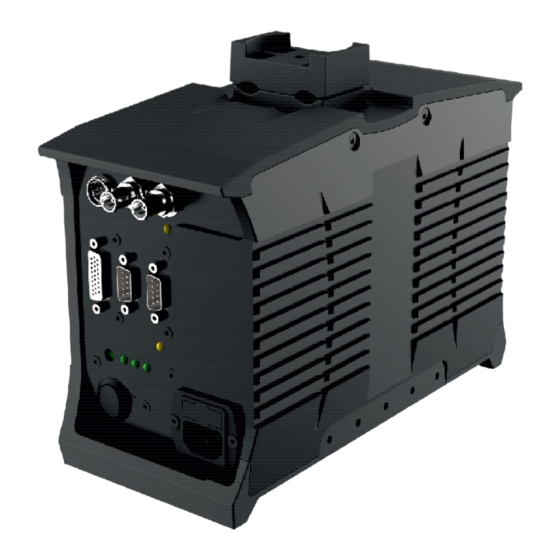
About this Manual The Virtual Reality interface (VRi) box has been designed to integrate with the Vinten Vector ‘i’ series heads and the Quattro SE pedestal. This manual covers the installation of the VRi box and its connections with compatible products and studio equipment. -
Page 7: Components And Connections
Components and Connections Front View 1 ..... . . DC In power supply socket 2 ..... . DC Out power supply socket 3 . -
Page 8: Rear View
Components and Connections Rear View 12 ......Mounting/cable clamp 13 ....... . . Cable clamp 14 . -
Page 9: Installation
Installation Box Contents 1 ..........VRi Box 2 . -
Page 10: Mounting To A Head
Mounting to a Head Mount to the second stage of the tripod if a two-stage tripod is used. The VRi box can be mounted directly to a Vinten Vector ‘i’ series head using the appropriate mounting kit. For information about mounting the VRi box to a head, refer to the Mounting Kits Installation Guide (publication part no. -
Page 11: Mounting To Lens Rods
Installation Mounting to Lens Rods When mounting the VRi box on to lens rods attached to a Vector head, the additional payload will affect the balance. This will need to be re- adjusted as necessary. To mount the VRi box onto lens rods, proceed as follows:... - Page 12 Installation CAUTION! Check and re-adjust the balance of the head after fitting the VRi box.
-
Page 13: Power Options
Installation Power Options Power Output CAUTION! 24 volts potentially present on the VDC OUT POWER POWER LEDS POWER OUPUT XLR socket. Check the compatibility of the auxiliary device SOURCE with the pin out configuration of the XLR socket. Refer to the Technical Specification section of this manual. -
Page 14: Genlock I/O Connections
Installation Genlock I/O Connections Genlock Source Note: Genlock output from the camera must be configured as genlock black. Genlock Source... -
Page 15: System Connections
Installation System Connections Ethernet Connection The ethernet (NET2) port is used to communicate with a Quattro SE pedestal. The ethernet port can also be used for diagnostic and CAUTION! All cables must be secured and dressed using servicing purposes. the cable clamp to minimise the risk of damage. Lens Encoder Connection Use the appropriate compatible cable to connect Canon or Fujinon lenses with quadrature encoder output. - Page 16 Use the PDA power/data cable (V3980-5051-9075) supplied with the the ‘i’ series head to the VRi box. The length of this cable PDA to connect the VRi box to the Vinten Radamec PDA. accommodates head mounting of the VRi box Alternatively, use the supplied RS232 null modem cable (D200-157) to Note: A longer version of the Devicelink.i cable will be required for...
-
Page 17: Powering Up
Installation Studio VR Connection Powering Up Connect the VR port to the studio VR graphics system. This port Before powering up the VRi box, ensure that all external cable provides formatted tracking data from the head, lens and pedestal. connections are secured correctly. To power up, operate the on/off rocker switch. -
Page 18: Troubleshooting
Check that the genlock signal from the studio supply is con- nected to the Genlock In BNC connector. If using a camera as a genlock source, the output must be If the problem persists, contact Vinten or configured to genlock black. Vinten Radamec customer support. -
Page 19: Maintenance And General Notices
Temperature range (operation) ..0°C to +40°C (32°F to +104°F) Cleaning Data Specification Supported data protocol..RS422 (Vinten Radamec D1 data packet) WARNING! Risk of electric shock. Always disconnect and RS232 compatible. isolate the product from the power supply before cleaning. - Page 20 General Notices VDC OUT XLR Socket Description -12V -24V +24V +12V Technical specifications are subject to change without notice.
-
Page 21: Fcc Certification
This product complies with Part 15 of the FCC Rules. Operation is subject to the following two conditions: This product may not cause harmful interference. V4083-0001 This product must accept any interference received, including interference that may cause undesired operations. -
Page 22: Pollution Statement
General Notices European Union Waste of Electrical and Electronic Equipment (WEEE) Directive (2002/96/EC) This symbol marked on the product or its packaging indicates that this product must not be disposed of with general household waste. In some countries or European Community regions separate collection systems have been set up to handle the recycling of electrical and electronic waste products. - Page 24 Publication part No. V4083-4980/2 inten Radamec itec Group brand...
Need help?
Do you have a question about the V4083-0001 and is the answer not in the manual?
Questions and answers