Table of Contents
Advertisement
Advertisement
Table of Contents
Troubleshooting

Summary of Contents for iDect FC6A series
- Page 1 B-1722(2) FC6A SERIES All-in-One Type User’s Manual...
-
Page 2: Safety Precautions
Emergency stop and interlocking circuits must be configured outside the FC6A Series MicroSmart. • If relays or transistors in the FC6A Series MicroSmart output circuits should fail, outputs may remain at on or off state. For output signals • which may cause serious accidents, configure monitor circuits outside the FC6A Series MicroSmart. -
Page 3: About This Manual
Description of the expansion module and cartridge settings that configure the usage of expansion modules and cartridges. Chapter 13: Troubleshooting Procedures to determine the cause of trouble and actions to be taken when any trouble occurs while operating the FC6A Series MicroSmart. - Page 4 CAN/CSA C22.2 No.213 • *1 Certain FC6A Series MicroSmart models are not compatible. For details, please contact IDEC Corporation. For details on compatible standards and EU directives, please contact the dealer where purchased or check the IDEC website. IMPORTANT INFORMATION Under no circumstances shall IDEC Corporation be held liable or responsible for indirect or consequential damages resulting from the use of or the application of IDEC PLC components, individually or in combination with other equipment.
-
Page 5: Related Manuals
ELATED ANUALS The following manuals related to the FC6A Series MicroSmart are available. Refer to them in conjunction with this manual. Type No. Manual Name Description Describes product specifications, installation and wiring instructions, instructions for FC6A Series MicroSmart basic programming operations and special functions, device and instruction lists, FC9Y-B1722 All-in-One Type User’s Manual... - Page 6 BBREVIATIONS SED IN THIS ANUAL Model Names Name Used in This Manual Type Number, Part Code, or Official Name FC6A Series MicroSmart FC6A Series MICROSmart FC6A-C16R1AE, FC6A-C16R1CE, FC6A-C16K1CE, FC6A-C16P1CE, FC6A-C24R1AE, FC6A-C24R1CE, FC6A-C24K1CE, FC6A-C24P1CE, All-in-One Type FC6A-C40R1AE, FC6A-C40R1CE, FC6A-C40K1CE, FC6A-C40P1CE, FC6A-C40R1DE, FC6A-C40R1DE, FC6A-C40K1DE, FC6A-C40P1DE...
-
Page 7: Table Of Contents
About This Manual..........................Preface-2 Related Manuals..........................Preface-4 Names and Abbreviations Used in this Manual ..................Preface-5 General Information HAPTER About the FC6A Series MicroSmart........................ 1-1 Features ..............................1-7 Special Functions............................1-8 Communication Functions .......................... 1-11 Maintenance Communication........................1-13 User Communication..........................1-14 Modbus Communication .......................... -
Page 8: Hapter
About the Menu Screen ..........................7-5 Basic Operations ............................7-6 Switching run/stop ............................7-9 Editing Programs ............................7-10 FC6A Series MicroSmart Environment Settings .....................7-12 Monitoring the FC6A Series MicroSmart .......................7-32 Checking/Clearing Error Information......................7-37 Displaying Arbitrary Messages........................7-39 Maintaining the SD Memory Card ........................7-40 Reading and Writing Recipe Files ........................7-42... - Page 9 Reading Error Data............................ 13-1 Special Data Registers for Error Information ....................13-3 General Error Codes ..........................13-3 FC6A Series MicroSmart Operating Status, Output, and ERR LED during Errors ..........13-4 Error Causes and Actions ........................... 13-4 User Program Execution Error ........................13-6 Troubleshooting Diagrams .........................
- Page 10 ABLE OF ONTENTS Preface-9 FC6A S ’ FC9Y-B1722 ERIES ICRO MART ANUAL...
-
Page 11: About The Fc6A Series Microsmart
CPU module. Inputs, outputs, and communication ports can be expanded according to application. The FC6A Series MicroSmart can also be linked to various types of external devices with communication functions that include maintenance communication, user communication, and Modbus communication. The FC6A Series MicroSmart is also equipped with functions for high-speed counters, pulses, flow calculation, and data logging functions. - Page 12 1: G ENERAL NFORMATION HMI module FC6A - PH 1 Interface specification 1: Communication connector Module type PH: HMI module Expansion I/O module FC6A - M 0 8 B R 1 Terminal specification 1: Pluggable terminal block 3: MIL connector Output type R: Relay output (Mixed I/O module only) K: Transistor sink output...
- Page 13 1: G ENERAL NFORMATION PID module FC6A - F 2 M R 1 Terminal specification 1: Pluggable terminal block Output type None: Voltage/current input R: Relay output Input type M: Multi input Control loop points 2: 2 points Module type F: PID module Expansion interface module FC6A - EXM 2...
- Page 14 1: G ENERAL NFORMATION Connector FC6A - P M 0 8 P N 0 5 Quantity per pack 02: 2 05: 5 Sale configuration PN: 1 pack Number of pins 03: 3 05: 5 08: 8 09: 9 10: 10 11: 11 12: 12 13: 13...
- Page 15 1: G ENERAL NFORMATION Battery holder FC6A - B H N 0 2 Quantity per pack 02: 2 05: 5 Sale configuration PN : 1 pack Type 2 1: Standard product Product classification BH: Battery holder FC6A S ’ FC9Y-B1722 ERIES ICRO MART...
- Page 16 1: G ENERAL NFORMATION CPU Module Type Numbers and Functions List Type numbers and functions Number of Inputs and Ethernet Serial SD Memory Analog Input/ Type Number Power Supply Cartridge Outputs Port Port 1 Port Port 1 Card Slot Volume Slots FC6A-C16R1AE 16 (496)
-
Page 17: Features
SD Memory Card The FC6A Series MicroSmart is equipped with an SD memory card slot. The log data of device values, configuration data, user programs, and system software can be saved to an optional SD memory card (HG9Z-XMS2) or a commercially available SD memory card (32 GB maximum). -
Page 18: Special Functions
This function acquires volume input as a 0 to 1,000 digital value in a special data register according to the position of the volume. There is one analog volume. Forced I/O The inputs and outputs of the FC6A Series MicroSmart can be forced on or off. This function can be used to check the I/O wiring or the user program operation. FC6A S ’... - Page 19 This function counts high-speed pulse inputs that cannot be measured in normal user program processing. Use this function for applications such as positioning control with a rotary encoder or motor control. The FC6A Series MicroSmart can use single-phase high-speed counters and two-phase high-speed counters. A maximum of six single-phase high-speed counters and a maximum of two two-phase high-speed counters can be used simultaneously.
- Page 20 MicroSmart can operate according to the current date and time. These functions can be used to control a time schedule for lighting or air conditioning equipments. The FC6A Series MicroSmart also supports daylight savings time and the date and time of the switch can be freely set to allow for use in any region.
-
Page 21: Communication Functions
NFORMATION Communication Functions The FC6A Series MicroSmart can perform RS232C and RS485 communication using serial port 1. The communication ports can be expanded by using communication cartridges to allow for multiple instances of RS232C and RS485 communication. The Ethernet port is standard equipment to enable communication using Ethernet. The CAN J1939 All-in-One Type is equipped with a CAN port to enable J1939 communication. - Page 22 1: G ENERAL NFORMATION Communication Ports, Serial Port 1, Communication Cartridge 1 and 2 Corresponding Table The communication ports that are used in serial communication support the following communication interfaces. Serial Port Type No. Port 1 Port 2 Port 3 FC6A-C16R1AE FC6A-C16R1CE FC6A-C16K1CE...
-
Page 23: Maintenance Communication
Maintenance Communication The maintenance communication of the FC6A Series MicroSmart enables you to check the operating status and I/O status of the FC6A Series MicroSmart, monitor and change device values, and download and upload user programs with the PLC programming software WindLDR installed on a computer. -
Page 24: User Communication
Cartridge ■ User Communication Using Serial Port 1 This example shows a system in which a FC6A Series MicroSmart receives the data read by a barcode reader. A barcode reader is connected to port 1 of the FC6A Series MicroSmart. -
Page 25: Data Link System
Data Link System The FC6A Series MicroSmart supports data link communication, and it can share data between CPU modules using serial port 1 and cartridge slots. The FC6A Series MicroSmart can also share data with FC5A Series and FC4A Series CPU modules. Configure the settings in WindLDR to enable distributed control of a maximum of 31 CPU modules. -
Page 26: Ethernet Communication
Be sure to consult your network administrator or Internet service provider. IDEC bears no responsibility for damages or problems caused due to security in Ethernet communication. Restrict the access to FC6A Series MicroSmart with IP addresses and ports by using appropriate measures such as the firewall. •... -
Page 27: Operator Interface Connectivity
Ethernet Port 1 CAN Port Cartridge ■ CAN Port Usage Example This example shows the FC6A Series MicroSmart communicating with a J1939-compatible engine. The CAN port of the CAN J1939 All-in-One Type is connected to the engine. CAN Port FC6A Series MicroSmart... - Page 28 1: G ENERAL NFORMATION 1-18 FC6A S ’ FC9Y-B1722 ERIES ICRO MART ANUAL...
-
Page 29: Normal Operating Conditions
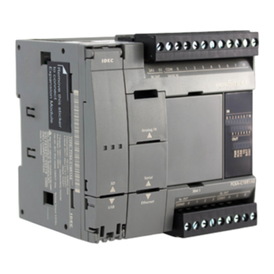
This chapter describes the part names and specifications of the modules that make up the FC6A Series MicroSmart. Various types of modules are available for the FC6A Series MicroSmart, including CPU modules (All-in-One Type, CAN J1939 All-in- One Type), expansion I/O modules (input modules, output modules, mixed I/O modules), functional modules (analog modules, PID modules), and option modules (expansion interface module, HMI module, analog cartridges, communication cartridges). -
Page 30: Cpu Module
(31) Serial Port 1 Cover (34) USB Port Cover (32) Ethernet Port 1 Cover (33) Power Supply Terminals Cover The content in brackets is the LED indicator name on the FC6A Series MicroSmart. LED Indicators 16-I/O Type 24-I/O Type 40-I/O Type... - Page 31 • When the FC6A Series MicroSmart is recognizing the SD memory card Slow flashing (1 s cycle) • When the FC6A Series MicroSmart is stopping access due to the SD memory card access stop flag (M8076) turning on (slow flashing, then off) Quick flashing (100 ms cycle) •...
- Page 32 The DC power type is available as the 24V DC power type and the 12V DC power type. (21) USB Port A mini-B type USB 2.0 connector. A USB cable can be attached to the FC6A Series MicroSmart and connected to a PC to download and upload user programs using WindLDR.
- Page 33 (28) Ethernet Port 1 Cover (29) Power Supply Terminals Cover The content in brackets is the LED indicator name on the FC6A Series MicroSmart. LED Indicators 0 1 2 3 4 5 6 7 10 11 12 13 14 15 16 17...
- Page 34 • When the FC6A Series MicroSmart is recognizing the SD memory card Slow flashing (1 s cycle) • When the FC6A Series MicroSmart is stopping access due to the SD memory card access stop flag (M8076) turning on (slow flashing, then off) Quick flashing (100 ms cycle) •...
- Page 35 The DC power type is available as the 24V DC power type and the 12V DC power type. (21) USB Port A mini-B type USB 2.0 connector. A USB cable can be attached to the FC6A Series MicroSmart and connected to a PC to download and upload user programs using WindLDR.
- Page 36 2: P RODUCT PECIFICATIONS Power Supply Specifications ■ AC Power Type Type No. FC6A-C16R1AE, FC6A-C24R1AE, FC6A-C40R1AE, FC6A-C40R1AEJ Rated Operating Voltage 100 to 240V AC Voltage Fluctuation Range 85 to 264V AC Rated Power Frequency 50/60 Hz (47 to 63 Hz) Maximum Power Consumption Standalone When Maximum Load is Connected...
- Page 37 2: P RODUCT PECIFICATIONS ■ 24V DC Power Type FC6A-C16R1CE, FC6A-C16K1CE, FC6A-C16P1CE, FC6A-C24R1CE, FC6A-C24K1CE, Type No. FC6A-C24P1CE, FC6A-C40R1CE, FC6A-C40K1CE, FC6A-C40P1CE, FC6A-C40R1CEJ, FC6A-C40K1CEJ, FC6A-C40P1CEJ Rated Power Voltage 24V DC Voltage Fluctuation Range 20.4 to 28.8V DC (including ripple) Maximum Power Consumption Standalone When Maximum Load is Connected FC6A-C16R1CE...
- Page 38 2: P RODUCT PECIFICATIONS FC6A-C16R1CE 350 g FC6A-C16K1CE 340 g FC6A-C16P1CE 340 g FC6A-C24R1CE 400 g FC6A-C24K1CE 380 g FC6A-C24P1CE 380 g Weight FC6A-C40R1CE 530 g FC6A-C40K1CE 480 g FC6A-C40P1CE 480 g FC6A-C40R1CEJ 530 g FC6A-C40K1CEJ 480 g FC6A-C40P1CEJ 480 g 2-10 FC6A S ’...
- Page 39 2: P RODUCT PECIFICATIONS ■ 12V DC Power Type FC6A-C40R1DE, FC6A-C40K1DE, FC6A-C40P1DE, FC6A-C40R1DEJ, FC6A-C40K1DEJ, Type No. FC6A-C40P1DEJ Rated Power Voltage 12V DC Voltage Fluctuation Range 10.2 to 18V DC (including ripple) Maximum Power Consumption Standalone When Maximum Load is Connected FC6A-C40R1DE 4.14 W (12V DC) 23.28 W (12V DC)
- Page 40 2: P RODUCT PECIFICATIONS Function Specifications ■ CPU Module Performance FC6A-C40R1AE FC6A-C40R1AEJ FC6A-C40R1CE FC6A-C40R1CEJ FC6A-C16R1AE FC6A-C24R1AE FC6A-C40K1CE FC6A-C40K1CEJ FC6A-C16R1CE FC6A-C24R1CE Type No. FC6A-C40P1CE FC6A-C40P1CEJ FC6A-C16K1CE FC6A-C24K1CE FC6A-C40R1DE FC6A-C40R1DEJ FC6A-C16P1CE FC6A-C24P1CE FC6A-C40K1DE FC6A-C40K1DEJ FC6A-C40P1DE FC6A-C40P1DEJ 72,000 bytes (9,000 steps) * Writable during run-time Program Data Program 640,000 bytes...
- Page 41 2: P RODUCT PECIFICATIONS Self-diagnostic Functions Keep data WDT check • • User program sum check (EEPROM) User program write check • • User program sum check (RAM) Power failure • • Timer/counter preset value sum check Clock error • •...
- Page 42 2: P RODUCT PECIFICATIONS Sensor External Output Power (AC Power Type Only) Type No. FC6A-C16R1AE, FC6A-C24R1AE, FC6A-C40R1AE, FC6A-C40R1AEJ Output Voltage/Current 24 V (+10%, -15%)/250 mA (however, capacitive load is 2,500 μF or lower) Not possible (an overcurrent protection circuit is built in, but there is a risk of damage from a Overload Detection long term short circuit.) Isolation between Internal Circuit...
- Page 43 2: P RODUCT PECIFICATIONS ■ All-in-One Type Only Analog Volume Points Data Resolution 0 to 1,000 Analog Input Points Input Range 0 to 10 V Data Resolution 0 to 1,000 Input Impedance Approx. 100 kΩ Error ±1% of full scale (±5% of full scale when noise is applied) Input Delay Time 12 ms (including the software filter) Maximum Allowed Steady Load...
- Page 44 2: P RODUCT PECIFICATIONS DC Input Specifications ■ AC Power Type, 24V DC Power Type FC6A-C40R1AE FC6A-C40R1CE FC6A-C16R1AE FC6A-C24R1AE FC6A-C40K1CE FC6A-C16R1CE FC6A-C24R1CE FC6A-C40P1CE Type No. FC6A-C16K1CE FC6A-C24K1CE FC6A-C40R1AEJ FC6A-C16P1CE FC6A-C24P1CE FC6A-C40R1CEJ FC6A-C40K1CEJ FC6A-C40P1CEJ Rated Input Voltage 24V DC shared sink/source Input Voltage Range 0.0 to 28.8V DC I0, I1, I6, I7...
- Page 45 2: P RODUCT PECIFICATIONS Operating Ranges The operating range of Type 1 (IEC 61131-2) input modules is as follows. I0, I1, I6, I7 I2 to I5, I10 to I27 Input Voltage (V DC) Input Voltage (V DC) 28.8 V 28.8 V ON Area ON Area 24 V...
- Page 46 2: P RODUCT PECIFICATIONS ■ 12V DC Power Type FC6A-C40R1DE, FC6A-C40K1DE, FC6A-C40P1DE, Type No. FC6A-C40R1DEJ, FC6A-C40K1DEJ, FC6A-C40P1DEJ Rated Input Voltage 12V DC shared sink/source Input Voltage Range 0.0 to 18.0V DC I0, I1, I6, I7 5 mA/point (at 12V DC) Rated Input Current I2 to I5, I10 to I27 6 mA/point (at 12V DC)
- Page 47 2: P RODUCT PECIFICATIONS Operating Ranges The operating range of Type 1 (IEC 61131-2) input modules is as follows. I0, I1, I6, I7 I2 to I5, I10 to I27 Input Voltage (V DC) Input Voltage (V DC) 18 V 18 V ON Area ON Area 12 V...
- Page 48 2: P RODUCT PECIFICATIONS Relay Output Specifications ■ AC Power Type, 24V DC Power Type, 12V DC Power Type FC6A-C40R1AE FC6A-C40R1CE FC6A-C16R1AE FC6A-C24R1AE FC6A-C40R1DE Type No. FC6A-C16R1CE FC6A-C24R1CE FC6A-C40R1AEJ FC6A-C40R1CEJ FC6A-C40R1DEJ No. of Outputs COM0 COM1 Output Points per Common Line COM2 ―...
- Page 49 2: P RODUCT PECIFICATIONS Transistor Sink Output Specifications ■ 24V DC power type Type No. FC6A-C16K1CE FC6A-C24K1CE FC6A-C40K1CE FC6A-C40K1CEJ No. of Outputs Output Points COM0 per Common COM1 ― ― Line Rated Load Voltage 24V DC Operating Load Voltage Range 20.4 to 28.8V DC Terminal Arrangement See "24V DC Power Type"...
- Page 50 2: P RODUCT PECIFICATIONS ■ 12V DC Power Type Type No. FC6A-C40K1DE FC6A-C40K1DEJ No. of Outputs Output Points COM0 per Common COM1 Line Rated Load Voltage 12V DC Operating Load Voltage Range 10.2 to 18.0V DC 10.2 to 16.0V DC Terminal Arrangement See "12V DC Power Type"...
- Page 51 2: P RODUCT PECIFICATIONS Transistor Protection Source Output Specifications ■ 24V DC power type Type No. FC6A-C16P1CE FC6A-C24P1CE FC6A-C40P1CE FC6A-C40P1CEJ No. of Outputs Output Points COM0 per Common COM1 ― ― Line Rated Load Voltage 24V DC Operating Load Voltage Range 20.4 to 28.8V DC Terminal Arrangement See "24V DC Power Type"...
- Page 52 2: P RODUCT PECIFICATIONS ■ 12V DC Power Type Type No. FC6A-C40P1DE FC6A-C40P1DEJ No. of Outputs Output Points COM0 per Common COM1 Line Rated Load Voltage 12V DC Operating Load Voltage Range 10.2 to 18.0V DC 10.2 to 16.0V DC Terminal Arrangement See "12V DC Power Type"...
- Page 53 Ambient Temperature, Input Voltage, I/O Simultaneous ON Ratio When the FC6A Series MicroSmart is used in an ambient temperature of 45°C or higher, reduce the input voltage and I/O simultaneous ON ratio (a%) according to the following diagrams. However, the following diagrams show the temperature conditions when the FC6A Series MicroSmart is normally installed.
- Page 54 2: P RODUCT PECIFICATIONS ■ Transistor protection source output type When no cartridges are installed, reduce the input voltage and I/O simultaneous ON ratio (a%) as shown in the following diagrams. • 24V DC Power Type Ambient Ambient Input I/O Output I/O Input Voltage (V DC) Input Voltage (V DC)
- Page 55 2: P RODUCT PECIFICATIONS When a cartridge is installed, reduce the input voltage and I/O simultaneous ON ratio (a%) as shown in the following diagrams. • 24V DC Power Type Ambient Ambient Input I/O Output I/O Input Voltage (V DC) Input Voltage (V DC) Temperature Temperature...
- Page 56 2: P RODUCT PECIFICATIONS Terminal Arrangement and Wiring Examples ■ AC Power Type 16-I/O Type: FC6A-C16R1AE (1) Power supply terminals AC Power Input : Fuse : Load (2) Sensor power terminals, input terminals DC Sink Input Wiring 2-wire Sensor +24V 0V I7 I10 Power Output 24V DC Input...
- Page 57 2: P RODUCT PECIFICATIONS 24-I/O Type: FC6A-C24R1AE (1) Power supply terminals AC Power Input : Fuse : Load (2) Sensor power terminals, input terminals DC Sink Input Wiring 2-wire Sensor +24V 0V I7 I10 I11 I12 I13 I14 I15 Power Output 24V DC Input 24V DC Input DC Source Input Wiring...
- Page 58 2: P RODUCT PECIFICATIONS 40-I/O Type: FC6A-C40R1AE, FC6A-C40R1AEJ (1) Power supply terminals AC Power Input : Fuse : Load (2) Sensor power terminals, input terminals DC Sink Input Wiring 2-wire Sensor +24V 0V I7 I10 I11 I12 I13 I14 I15 I16 I17 I20 I21 I22 I23 I24 I25 I26 I27 Power Output 24V DC Input 24V DC Input...
- Page 59 2: P RODUCT PECIFICATIONS ■ 24V DC Power Type 16-I/O type: FC6A-C16R1CE, FC6A-C16K1CE, FC6A-C16P1CE (1) Power supply terminals 24V DC Power Input +24V - External Power 24V DC : Fuse : Load (2) Input terminals DC Sink Input Wiring External Power 2-wire 24V DC Sensor...
- Page 60 2: P RODUCT PECIFICATIONS 24-I/O type: FC6A-C24R1CE, FC6A-C24K1CE, FC6A-C24P1CE (1) Power supply terminals 24V DC Power Input +24V - External Power 24V DC : Fuse : Load (2) Input terminals DC Sink Input Wiring External Power 2-wire 24V DC Sensor NC.
- Page 61 2: P RODUCT PECIFICATIONS 40-I/O type: FC6A-C40R1CE, FC6A-C40K1CE, FC6A-C40P1CE, FC6A-C40R1CEJ, FC6A-C40K1CEJ, FC6A-C40P1CEJ (1) Power supply terminals 24V DC Power Input +24V - External Power 24V DC : Fuse : Load (2) Input terminals DC Sink Input Wiring External Power 2-wire 24V DC Sensor NC.
- Page 62 2: P RODUCT PECIFICATIONS ■ 12V DC Power Type 40-I/O type: FC6A-C40R1DE, FC6A-C40K1DE, FC6A-C40P1DE, FC6A-C40R1DEJ, FC6A-C40K1DEJ, FC6A-C40P1DEJ (1) Power supply terminals 12V DC Power Input +12V - External Power 12V DC : Fuse : Load (2) Input terminals DC Sink Input Wiring External Power 2-wire Sensor...
- Page 63 2: P RODUCT PECIFICATIONS Other Inputs and Ports ■ All-in-One Type (1) Analog input Signal Wire Cable Color AN(+) AN(-) Black (2) Serial Port 1 Signal Wire Signal Wire (RS-232C) (RS-485) ― ― ― ― ― ― ― ― Shell Shield Shield *1 Shell is connected to PE or FE on the power supply terminals.
- Page 64 CAN external power supply (+). (V+) (This port is not used with the FC6A Series MicroSmart.) *1 Internally connected to the SG via a resistor and capacitor connected in a series. (R = 1 Ω, 0.68 μF) (2) Ethernet Port 1...
-
Page 65: Expansion I/O Modules
2: P RODUCT PECIFICATIONS Expansion I/O Modules Expansion I/O modules are available in three types of modules: input modules equipped with input terminals, output modules equipped with output terminals, and mixed I/O modules equipped with both input terminals and output terminals. Input module Parts Description Example: FC6A-N08B1... - Page 66 2: P RODUCT PECIFICATIONS Function Specifications ■ DC Input Module Specifications Type No. FC6A-N08B1 FC6A-N16B1 FC6A-N16B3 FC6A-N32B3 Rated Input Voltage 24V DC shared sink/source Operating Load Voltage Range 0.0 to 28.8V DC Rated Input Current 7 mA/point (at 24V DC) 5 mA/point (at 24V DC) 8 (8 points in 1 32 (16 points in 1...
- Page 67 Ambient Temperature, Input Voltage, I/O Simultaneous ON Ratio When the FC6A Series MicroSmart is used in an ambient temperature of 30°C or higher, reduce the input voltage and I/O simultaneous ON ratio (a%) according to the following diagrams. However, the following diagrams show the temperature conditions when the FC6A Series MicroSmart is normally installed.
- Page 68 2: P RODUCT PECIFICATIONS ■ AC Input Module Specifications Type No. FC6A-N08A11 Rated Input Voltage 100 to 120V AC Operating Load Voltage Range 0 to 132V AC Rated Power Frequency 50/60 Hz Rated Input Current 15 mA/1 point (at 120V AC, 50/60 Hz) Input Points 8 points in 2 common lines Terminal Arrangement...
- Page 69 At conditions where the ambient temperature is 55°C and the input voltage is 132 V, the inputs can be 100% used. However, the following diagrams show the temperature conditions when the FC6A Series MicroSmart is normally installed. Note: Normally installed means the state in the diagram in "Normal Installation State" on page 3-1.
- Page 70 2: P RODUCT PECIFICATIONS Terminal Arrangement and Wiring Examples ■ FC6A-N08B1 Terminal block type Applicable connector: FC6A-PMTB11PN02 (screw fastened type), FC6A-PMSB11PN02 (spring clamp type) The 3 COM lines are connected in the module. DC.IN For wiring precautions, see "Input/Output Wiring" on page 3-15. DC Sink Input Wiring Example Terminal No.
- Page 71 2: P RODUCT PECIFICATIONS ■ FC6A-N16B1 Terminal block type Applicable connector: FC6A-PMTC10PN02 (screw fastened type), FC6A-PMSC10PN02 (spring clamp type) The 4 COM lines are connected in the module. DC.IN For wiring precautions, see "Input/Output Wiring" on page 3-15. DC Sink Input Wiring Example Terminal No.
- Page 72 2: P RODUCT PECIFICATIONS ■ FC6A-N16B3 Terminal block type Applicable connector: FC4A-PMC20P The two COM lines are each connected in the module. For wiring precautions, see "Input/Output Wiring" on page 3-15. For the connector cable, see "Cables" on page A-14. DC Sink Input Wiring Example DC.IN Terminal No.
- Page 73 2: P RODUCT PECIFICATIONS ■ FC6A-N32B3 Connector type Applicable connector: FC4A-PMC20P The two COM0 and COM1 lines are each connected in the module. Each of the terminals for COM0 and COM1 are independent. DC.IN For wiring precautions, see "Input/Output Wiring" on page 3-15. For the connector cable, see "Cables"...
- Page 74 2: P RODUCT PECIFICATIONS ■ FC6A-N08A11 Terminal block type Applicable connector: FC6A-PMTB11PN02 (screw fastened type), FC6A-PMSB11PN02 (spring clamp type) Each of the terminals for COM0 and COM1 are independent. For wiring precautions, see "Input/Output Wiring" on page 3-15. Ry.OUT AC input wiring example Terminal No.
- Page 75 2: P RODUCT PECIFICATIONS Output module Parts Description Example: FC6A-R081 Example: FC6A-T32K3 (2) Output LEDs (2) Output LEDs (5) Expansion Connector (5) Expansion Connector (4) Cable Terminal (3) Terminal Name Labels (1) Type Label (3) Terminal Name Label (4) Cable Terminals (4) Cable Terminal (1) Type Label Indicates the output module type no.
- Page 76 2: P RODUCT PECIFICATIONS Function Specifications ■ Relay Output Module Specifications Type No. FC6A-R081 FC6A-R161 No. of Outputs 8 (4 points in 1 common line) 16 (8 points in 1 common line) Output Type 1a contact Terminal Arrangement See 2-51 See 2-51 2 A maximum Load Current...
- Page 77 2: P RODUCT PECIFICATIONS ■ Transistor Sink Output Module Specifications Type No. FC6A-T08K1 FC6A-T16K1 FC6A-T16K3 FC6A-T32K3 Output Signal Transistor sink output Rated Load Voltage 24V DC Operating Load Voltage Range 20.4 to 28.8V DC No. of Outputs (8 points in 1 (16 points in 1 (16 points in 1 common line) common line)
- Page 78 2: P RODUCT PECIFICATIONS ■ Transistor Protection Source Output Module Specifications Type No. FC6A-T08P1 FC6A-T16P1 FC6A-T16P3 FC6A-T32P3 Output Signal Transistor protection source output Rated Load Voltage 24V DC Operating Load Voltage Range 20.4 to 28.8V DC No. of Outputs (8 points in 1 (16 points in 1 (16 points in 1 common line) common line)
- Page 79 2: P RODUCT PECIFICATIONS Terminal Arrangement and Wiring Examples ■ FC6A-R081 Terminal block type Applicable connector: FC6A-PMTB11PN02 (screw fastened type), FC6A-PMSB11PN02 (spring clamp type) Each of the terminals for COM0 and COM1 are independent. Ry.OUT For wiring precautions, see "Input/Output Wiring" on page 3-15. : Fuse : Load Terminal No.
- Page 80 2: P RODUCT PECIFICATIONS ■ FC6A-T08K1, FC6A-T08P1 Terminal block types Applicable connector: FC6A-PMTB11PN02 (screw fastened type), FC6A-PMSB11PN02 (spring clamp type) For wiring precautions, see "Input/Output Wiring" on page 3-15. : Fuse : Load FC6A-T08K1 Terminal No. Tr.OUT COM(-) COM(-) COM(-) COM(-) Insert a fuse that corresponds to the load.
- Page 81 2: P RODUCT PECIFICATIONS ■ FC6A-T16K1, FC6A-T16P1 Terminal block types Applicable Connector: FC6A-PMTC10PN02 (screw fastened type), FC6A-PMSC10PN02 (spring clamp type) For wiring precautions, see "Input/Output Wiring" on page 3-15. : Fuse : Load FC6A-T16K1 Terminal No. Tr.OUT COM(-) COM(-) COM(-) COM(-) Insert a fuse that corresponds to the load.
- Page 82 2: P RODUCT PECIFICATIONS ■ FC6A-T16K3, FC6A-T16P3 Terminal block types Applicable connector: FC4A-PMC20P The two COM(+) and COM(-) lines are each connected in the module. The two +V and -V lines are each connected in the module. For wiring precautions, see "Input/Output Wiring" on page 3-15. For the connector cable, see "Cables"...
- Page 83 2: P RODUCT PECIFICATIONS ■ FC6A-T32K3 Terminal block type Applicable connector: FC4A-PMC20P The two COM0(-) and COM1(-) lines are each connected in the module. Each of the terminals for COM0(-) and COM1(-) are independent. Tr.OUT The two +V0 and +V1 lines are each connected in the module. Each of the terminals for +V0 and +V1 are independent.
- Page 84 2: P RODUCT PECIFICATIONS ■ FC6A-T32P3 Terminal block type Applicable connector: FC4A-PMC20P The two COM0(+) and COM1(+) lines are each connected in the module. Each of the terminals for COM0(+) and COM1(+) are independent. Tr.OUT The two -V0 and -V1 lines are each connected in the module. Each of the terminals for -V0 and -V1 are independent.
- Page 85 2: P RODUCT PECIFICATIONS Mixed I/O module Parts Description Example: FC6A-M08BR1 Example: FC6A-M24BR1 (2) Input LEDs (2) Input LEDs (5) Expansion Connector Output LEDs Output LEDs (5) Expansion Connector (4) Cable Terminal (3) Terminal Name Labels (1) Type Label (3) Terminal Name Label (4) Cable Terminals (4) Cable Terminal (1) Type Label...
- Page 86 2: P RODUCT PECIFICATIONS Function Specifications ■ Power Supply Specifications Type No. FC6A-M08BR1 FC6A-M24BR1 Input Points 4 (4 points in 1 common line) 16 (16 points in 1 common line) Points No. of Outputs 4 (4 points in 1 common line) 8 (4 points in 1 common line) Terminal Arrangement See 2-61...
- Page 87 Ambient Temperature, Input Voltage, I/O Simultaneous ON Ratio When the FC6A Series MicroSmart is used in an ambient temperature of 45°C or higher, reduce the input voltage and I/O simultaneous ON ratio (a%) according to the following diagrams. However, the following diagrams show the temperature conditions when the FC6A Series MicroSmart is normally installed.
- Page 88 2: P RODUCT PECIFICATIONS ■ Output Specifications Type No. FC6A-M08BR1 FC6A-M24BR1 Output Points COM1 per Common COM2 ― Line Output Type 1a contact 2 A maximum Load Current 1 Common 7 A maximum Minimum Switching Load 1.0 mA/5.0V DC (reference value) Initial Contact Resistance 30 mΩ...
- Page 89 2: P RODUCT PECIFICATIONS Terminal Arrangement and Wiring Examples ■ FC6A-M08BR1 Terminal block type Applicable Connector: FC6A-PMTB11PN02 (screw fastened type), FC6A-PMSB11PN02 (spring clamp type) Each of the terminals for COM0 and COM1 are independent. For wiring precautions, see "Input/Output Wiring" on page 3-15. DC.IN : Fuse : Load...
- Page 90 2: P RODUCT PECIFICATIONS ■ FC6A-M24BR1 Terminal block type Applicable Connector: FC6A-PMTC17PN02 (screw fastened type), FC6A-PMSC17PN02 (spring clamp type) FC6A-PMTC11PN02 (screw fastened type), DC.IN Ry.OUT FC6A-PMSC11PN02 (spring clamp type) The 3 COM lines are connected in the module. For wiring precautions, see "Input/Output Wiring" on page 3-15. DC Sink Input Wiring Example Terminal No.
-
Page 91: Functional Module
2: P RODUCT PECIFICATIONS Functional module Functional modules are available as analog modules equipped with analog inputs and analog outputs and PID modules that perform temperature control with analog input. Analog Module Parts Description Example: FC6A-J2C1 Example: FC6A-L06A1 (2) Power LED [PWR] (2) Power LED [PWR] (5) Expansion Connector (5) Expansion Connector... - Page 92 2: P RODUCT PECIFICATIONS Model List Module type Cable Terminal Type I/O Points I/O Signal Type No. Voltage input (0 to 10 V, -10 to +10 V) Terminal block type (5.08 mm pitch) FC6A-J2C1 Current input (4 to 20 mA, 0 to 20 mA) Voltage input (0 to 10 V, -10 to +10 V) Terminal block type (3.81 mm pitch) FC6A-J4A1...
- Page 93 2: P RODUCT PECIFICATIONS Function Specifications ■ Analog Input Specifications Analog Input Module Type No. FC6A-J2C1 FC6A-J4A1 FC6A-J8A1 FC6A-J4CN1 FC6A-J8CU1 0 to 10 V Voltage ― -10 to 10 V 4 to 20 mA Current ― 0 to 20 mA (K) -200 to 1,300°C (-328 to 2,372°F) (J) -200 to 1,000°C (-328 to 1,832°F) (R) 0 to 1,760°C (32 to 3,200°F)
- Page 94 2: P RODUCT PECIFICATIONS Type No. FC6A-J2C1 FC6A-J4A1 FC6A-J8A1 FC6A-J4CN1 FC6A-J8CU1 Voltage 65,536 (16 bits) 4,096 (12 bits) 65,536 (16 bits) ― Current 65,536 (16 bits) 4,096 (12 bits) 65,536 (16 bits) ― K: 15,000 (14 bits) J: 12,000 (14 bits) R: 17,600 (15 bits) S: 17,600 (15 bits) Thermocouple...
- Page 95 2: P RODUCT PECIFICATIONS Type No. FC6A-J2C1 FC6A-J4A1 FC6A-J8A1 FC6A-J4CN1 FC6A-J8CU1 Effect of Improper Input Connection No damage Maximum Permanent Allowed Overload 13V DC, 40 mA or lower (No Damage) Selection of Input Type and Input Range Using programming software Calibration or Verification to Maintain Rated Not possible Accuracy...
- Page 96 2: P RODUCT PECIFICATIONS Type No. FC6A-L06A1 FC6A-L03CN1 Voltage 4,096 (12 bits) 65,536 (16 bits) Current 4,096 (12 bits) 65,536 (16 bits) K: 15,000 (14 bits) J: 12,000 (14 bits) R: 17,600 (15 bits) S: 17,600 (15 bits) Thermocouple ― B: 18,200 (15 bits) E: 10,000 (14 bits) T: 6,000 (13 bits)
- Page 97 2: P RODUCT PECIFICATIONS Input Internal Circuit FC6A-J2C1, FC6A-J4A1, FC6A-J8A1, FC6A-L06A1 2 MΩ 10 Ω Input Circuit 39 kΩ Switching Signal – FC6A-J4CN1, FC6A-L03CN1 Voltage Supply 10 Ω 2 MΩ 39 kΩ – Switching Signal B’ Voltage Supply FC6A-J8CU1 Voltage Supply Input Circuit –...
- Page 98 2: P RODUCT PECIFICATIONS ■ Analog Output Specifications Voltage Current Output Type and Output Range 0 to 10 V 4 to 20 mA -10 to 10 V 0 to 20 mA Impedance 1 kΩ or higher 300 Ω or lower Load Load Type Resistive load...
- Page 99 Caution the position shown in the following diagram. (Applicable when equipment containing the FC6A Series MicroSmart is destined for Europe) Do not connect a thermocouple to a part with hazardous voltage (60V DC or peak 42.4V DC or higher part).
- Page 100 2: P RODUCT PECIFICATIONS ■ FC6A-J4A1 Terminal block type Applicable Connector: FC6A-PMTC10PN02 (screw fastened type), FC6A-PMSC10PN02 (spring clamp type) For wiring precautions, see "Input/Output Wiring" on page 3-15. ANALOG : Fuse Terminal No. 24V DC Analog Voltage/ current Output Device Analog Voltage/ current Output Device Analog Voltage/...
- Page 101 2: P RODUCT PECIFICATIONS ■ FC6A-J4CN1 Terminal block type Applicable Connector: FC6A-PMTC10PN02 (screw fastened type), FC6A-PMSC10PN02 (spring clamp type) For wiring precautions, see "Input/Output Wiring" on page 3-15. ANALOG : Fuse Terminal No. 24V DC Analog Voltage/ current Output Device B’...
- Page 102 2: P RODUCT PECIFICATIONS ■ FC6A-K4A1 Terminal block type Applicable Connector: FC6A-PMTB11PN02 (screw fastened type), FC6A-PMSB11PN02 (spring clamp type) For wiring precautions, see "Input/Output Wiring" on page 3-15. ANALOG : Fuse Terminal No. 24V DC Analog Voltage/ OUT0 current Input Device Analog Voltage/ OUT1 current Input Device...
- Page 103 2: P RODUCT PECIFICATIONS ■ FC6A-L06A1 Terminal block type Applicable Connector: FC6A-PMTC10PN02 (screw fastened type), FC6A-PMSC10PN02 (spring clamp type) For wiring precautions, see "Input/Output Wiring" on page 3-15. ANALOG : Fuse Terminal No. 24V DC Analog Voltage/ OUT0 current Input Device Analog Voltage/ OUT1 current Input Device...
- Page 104 2: P RODUCT PECIFICATIONS PID Module Parts Description Example: FC6A-F2M1 (2) Power LED [PWR] (3) Control Output LEDs [OUT0, OUT1] (4) Event Output LEDs [EVT0, EVT1] (12) Expansion Connector (5) Auto Tuning/auto Reset LEDs [AT0, AT1] (6) Manual Mode LEDs [MT0, MT1] (7) Fixed Value Control Mode/program Control Mode LEDs [F/P0, F/P1] (8) Program Control Execution/hold LEDs [R/H0, R/H1] (9) External SP Enabled/disabled LEDs [R/L]...
- Page 105 2: P RODUCT PECIFICATIONS (5) Auto Tuning/auto Reset LEDs [AT0, AT1] Flashing: When executing auto tuning or auto reset Off: When auto tuning or auto reset is stopped (6) Manual Mode LEDs [MT0, MT1] On: When program control mode is selected Off: When auto mode is selected (7) Fixed Value Control Mode/program Control Mode LEDs [F/P0, F/P1] On: During program control mode...
- Page 106 2: P RODUCT PECIFICATIONS Power Supply Specifications Type No. FC6A-F2M1 FC6A-F2MR1 Power Supply Voltage 24V DC External Power Allowed Fluctuation 20.4 to 28.8V DC Range Terminal Arrangement See "Terminal Arrangement and Wiring Examples" on page 2-83 Insertion/Removal Connector 100 times minimum Durability Module 5V DC...
- Page 107 2: P RODUCT PECIFICATIONS Type No. FC6A-F2M1, FC6A-F2MR1 Within ±0.2% of full scale or ±2°C (4°F), whichever is larger Cold junction compensation accuracy: ±1.0°C or lower However, R, S input 0 to 200°C (0 to 400°F) is within ±6°C (12°F) Thermocouple B input 0 to 300°C (0 to 600°F) is outside the guaranteed range of Maximum Error at...
- Page 108 2: P RODUCT PECIFICATIONS Type No. FC6A-F2M1, FC6A-F2MR1 Type Input Value per Step Pt100 1°C (°F) Pt100 (with decimal 0.1°C (°F) Input Value per Resistance point) Step Thermometer JPt100 1°C (°F) Data JPt100 (with decimal 0.1°C (°F) point) Data Type in Application Program Can be arbitrarily set for each CH in a range between -32,768 to 32,767 Monotonicity Input Data Out of Range...
- Page 109 2: P RODUCT PECIFICATIONS ■ Output Specifications Type No. FC6A-F2M1 FC6A-F2MR1 Output Transistor protection source output Digital Output Relay output Type and (12V DC output) Output Analog Output 4 to 20 mA ― Range Digital Output Max 40 mA (12V DC) ―...
- Page 110 2: P RODUCT PECIFICATIONS Output Delay Input to Relay Output Relay Status OFF Bounce: 6 ms maximum OFF Delay: 15 ms maximum ON Bounce: 6 ms maximum ON Delay: 10 ms maximum ■ Program Performance Item Specifications Time setting accuracy Within ±0.5% of the set time Progression time error after power interruption 6 minutes maximum...
- Page 111 2: P RODUCT PECIFICATIONS Terminal Arrangement and Wiring Examples When connecting the terminal, insert an IEC 60127-approved fuse suitable for the applied voltage and current draw at • Caution the position shown in the following diagram. This is required when equipment containing the MicroSmart is destined for Europe. Do not connect a thermocouple to a part with hazardous voltage (60V DC or peak 42.4V DC or higher part).
- Page 112 2: P RODUCT PECIFICATIONS Precautions when Supplying Power to the PID Module When the PID module and the CPU module are set to the same power supply, the PID module will be initialized for a maximum of approximately 5 seconds after the power is turned on and the CPU module is set to run, so the parameters will not be stable. Always enable control after the module status flag changes to "0001H"...
-
Page 113: Option Module
2: P RODUCT PECIFICATIONS Option module Option modules are available as the expansion interface module, the HMI module, analog cartridges, and communication cartridges. Expansion Interface Module The number of expansion modules that can be connected to the CPU module (basic expansion side) is 7 modules, but this can be increased to 8 additional expansion modules (expansion interface side, maximum 256 I/O points) by installing the expansion interface module. - Page 114 2: P RODUCT PECIFICATIONS Function Specifications Type No. FC6A-EXM2 Rated Operating Voltage 24V DC (supplied from external power) Voltage Fluctuation Range 20.4 to 28.8V DC (including ripple) Internal Power CPU module side supply 20 mA (5V DC), 0 mA (24V DC) Current Draw External Power When maximum number of modules is connected...
- Page 115 2: P RODUCT PECIFICATIONS Power Supply Precautions When supplying power to the CPU module and to the expansion interface module with different power supplies, turn the modules on and off in • the order in the following table. An error may occur on the CPU module if the power on order or the power off order is mistaken. Power Supply Order Turn on the expansion interface module and the CPU module at the same time, or in expansion interface module →...
- Page 116 This cover prevents the mistaken operation of the operation buttons. Open the front cover when using the operation buttons and when installing or ejecting the cartridge. (2) LCD Displays the menus to control the FC6A Series MicroSmart and display the status and settings for the FC6A Series MicroSmart. (3) Cartridge Slot 3 This slot is used for installing an analog cartridge.
- Page 117 2: P RODUCT PECIFICATIONS (9) Dummy Cartridge A removable dummy cartridge that protects the cartridge slot. Remove the dummy cartridge when connecting an analog cartridge. (10) HMI-Ethernet Port This port allows Ethernet communication with connected devices that are equipped with an Ethernet interface. Function Specifications Type No.
- Page 118 2: P RODUCT PECIFICATIONS Analog Cartridges The CPU module and the HMI module can be expanded with a maximum of 6 analog inputs or analog outputs. For details on analog cartridges, see "Analog Cartridge" on page 10-1. Parts Description (1) Channel 0 terminals The terminals connect an input device or an output device.
- Page 119 2: P RODUCT PECIFICATIONS ■ Analog Output Specifications Type No. FC6A-PK2AV FC6A-PK2AW Output Voltage 0 to 10V DC ― Type and Output Current ― 4 to 20mA DC Range Impedance 2 kΩ or higher 500 Ω or lower Load Load Type Resistive load DA Conversion Time Max 40 ms...
- Page 120 2: P RODUCT PECIFICATIONS Type No. FC6A-PJ2A FC6A-PJ2CP Input Type Voltage Current Resistance Thermometer Thermocouple ±0.1% of full scale Cold junction compensation accuracy ±4.0°C or lower Exceptions R, S thermocouple error: Maximum Error at ±6.0°C ±0.1% of full scale ±0.1% of full scale 25°C (0 to 200°C range only) Input Error...
- Page 121 2: P RODUCT PECIFICATIONS Wiring Arrangement and Wiring Examples Do not connect a thermocouple to a part with hazardous voltage (60V DC or peak 42.4V DC or higher part). • Caution Before turning on the power, please check that the wiring is correct. If the wiring is incorrect, the analog cartridge may •...
- Page 122 2: P RODUCT PECIFICATIONS Communication Cartridges Communication cartridges can add RS-232C communication ports and RS-485 communication ports when connected to the CPU module's cartridge slots. These cartridges support the maintenance communication function, the user communication function, and the Modbus communication function. The RS-485 cartridge also supports the data link function. Note: The communication cartridges can be used by connecting them to the CPU module's cartridge connectors.
- Page 123 2: P RODUCT PECIFICATIONS Function Specifications Type No. FC6A-PC1 FC6A-PC3 Rated Power Voltage 5.0 V, 3.3 V (supplied from module) 5.0 V, 3.3 V (supplied from module) 5.0 V: Max 23 mA 5.0 V: Max 23 mA Current Draw 3.3 V: Max 6 mA 3.3 V: Max 6 mA Weight 15 g...
- Page 124 2: P RODUCT PECIFICATIONS Terminal Arrangement and Wiring Examples Notes: For the cables to use for wiring, fabricate and use the recommended cable or an equivalent type of shielded cable. • When there is a risk of malfunction due to noise, ground the shielded cables. •...
-
Page 125: Dimensions
2: P RODUCT PECIFICATIONS Dimensions CPU Modules All-in-One Type 16-I/O Type: FC6A-C16R1AE, FC6A-C16R1CE, FC6A-C16K1CE, FC6A-C16P1CE 130.9 114.3 95.0 73.0 All dimensions in mm. 24-I/O Type: FC6A-C24R1AE, FC6A-C24R1CE, FC6A-C24K1CE, FC6A-C24P1CE 130.9 114.3 110.0 73.0 All dimensions in mm. FC6A S ’ FC9Y-B1722 2-97 ERIES... - Page 126 2: P RODUCT PECIFICATIONS 40-I/O Type: FC6A-C40R1AE, FC6A-C40R1CE, FC6A-C40K1CE, FC6A-C40P1CE, FC6A-C40R1DE, FC6A-C40K1DE, FC6A-C40P1DE 130.9 114.3 163.0 73.0 All dimensions in mm. CAN J1939 All-in-One Type 40-I/O Type: FC6A-C40R1AEJ, FC6A-C40R1CEJ, FC6A-C40K1CEJ, FC6A-C40P1CEJ, FC6A-C40R1DEJ, FC6A-C40K1DEJ, FC6A-C40P1DEJ 130.9 114.3 11.3 73.0 163.0 86.2 All dimensions in mm.
- Page 127 2: P RODUCT PECIFICATIONS Expansion Modules and Option Modules Input modules: FC6A-N08B1, FC6A-N08A11 Output modules: FC6A-R081, FC6A-T08K1, FC6A-T08P1 Mixed I/O modules: FC6A-M08BR1 Analog modules: FC6A-J2C1, FC6A-K4A1, FC6A-L03CN1 23.6 15.8 73.0 All dimensions in mm. *1 9.3 mm when the clamp is pulled out. Input modules: FC6A-N16B1 Output modules:...
- Page 128 2: P RODUCT PECIFICATIONS Input modules: FC6A-N16B3 Output modules: FC6A-T16K3, FC6A-T16P3 17.6 10.1 73.0 All dimensions in mm. *1 9.3 mm when the clamp is pulled out. Input modules: FC6A-N32B3 Output modules: FC6A-T32K3, FC6A-T32P3 30.2 10.1 73.0 All dimensions in mm. *1 9.3 mm when the clamp is pulled out.
- Page 129 2: P RODUCT PECIFICATIONS Expansion interface module: FC6A-EXM2 39.2 15.2 73.0 All dimensions in mm. *1 9.3 mm when the clamp is pulled out. HMI module: FC6A-PH1 74.5 73.0 119.5 148.7 All dimensions in mm. *1 9.3 mm when the clamp is pulled out. *2 This dimension is 0 mm when the eject button is locked.
- Page 130 2: P RODUCT PECIFICATIONS 2-102 FC6A S ’ FC9Y-B1722 ERIES ICRO MART ANUAL...
-
Page 131: Installation And Wiring
Special expertise is required to install, wire, program, and operate the FC6A Series MicroSmart. People without such • expertise must not use the FC6A Series MicroSmart. Prevent metal fragments and pieces of wire from dropping inside the FC6A Series MicroSmart housing. Put a cover on the • Caution FC6A Series MicroSmart modules during installation and wiring. - Page 132 NSTALLATION AND IRING The FC6A Series MicroSmart can be mounted with the following orientation when the operating temperature is 35°C or lower. Side Orientation (Use this orientation with an operating temperature of 35°C or lower.) The FC6A Series MicroSmart cannot be mounted with the following orientations.
- Page 133 3: I NSTALLATION AND IRING Mounting Space To allow for heat dissipation and facilitate replacement, ensure that there are at least 20 to 40 mm between the FC6A Series MicroSmart and surrounding equipment and ducts. 40 mm 20 mm minimum...
-
Page 134: Assembly Methods
Assembly Methods This section describes how to assemble the FC6A Series MicroSmart. Assemble the FC6A Series MicroSmart before mounting it to a DIN rail or directly mounting it. When mounting the FC6A Caution Series MicroSmart to a DIN rail, if it is assembled after being mounted to the DIN rail, there is a risk of damage. - Page 135 HMI module has been pushed onto the CPU module. The HMI module is now locked on the CPU module. Communication Connector Eject Button Do not perform this work when the FC6A Series MicroSmart is powered. Otherwise there is a risk of damage. Caution FC6A S ’...
- Page 136 1 on the CPU module. Cartridge Slot 1 Analog Cartridge Do not perform this work when the FC6A Series MicroSmart is powered. Otherwise there is a risk of damage. • Caution Attach and remove the cartridge straight in relation to the CPU module. If you attach or remove the cartridge at an angle, •...
- Page 137 3 on the HMI module. Cartridge Slot 3 Analog Cartridge Do not perform this work when the FC6A Series MicroSmart is powered. Otherwise there is a risk of damage. • Caution Attach and remove the cartridge straight in relation to the HMI module. If you attach or remove the cartridge at an angle, •...
- Page 138 3: I NSTALLATION AND IRING Opening and Closing the Front Cover of the HMI Module The following procedure describes how to open and close the front cover of the HMI module. Opening the Front Cover Always unlock the front cover before opening it with the following procedure. Otherwise there is a risk of damage to the Caution HMI module.
- Page 139 3: I NSTALLATION AND IRING Applying too much force to the front cover may cause it to fall off. Caution If this happens, make the front cover vertical with the HMI module as shown in the following figure, and then slowly push on the part indicated by the arrow.
-
Page 140: Mounting On Din Rail
Supported rails: IDEC BAA1000 (Length: 1,000 mm) Rail bracket: BNL6PN10 The FC6A Series MicroSmart can also be mounted by hooking it onto the DIN rail when the DIN rail clamp is raised and pushing it on until it • clicks. - Page 141 NSTALLATION AND IRING Removing from DIN Rail Lower the FC6A Series MicroSmart's DIN rail clamp with a flathead screwdriver (1) and lift it up while pulling forward (1). DIN Rail (2) Pull outward and upward. (1) Lower DIN Rail clamp.
- Page 142 Mounting Hole Layout for Direct Mounting on Panel Surface As shown in the following diagram, mount the FC6A Series MicroSmart to the mounting plate with M4 pan head screws. Always give sufficient consideration to operability, ease-of-maintenance, and environmental resistance when deciding on the mounting position.
- Page 143 3: I NSTALLATION AND IRING ■ Expansion Modules and Option Modules Input modules: FC6A-N08B1, FC6A-N16B1, FC6A-N08A11 Output modules: FC6A-R081, FC6A-R161, FC6A-T08K1, FC6A-T08P1, FC6A-T16K1, FC6A-T16P1 Mixed I/O modules: FC6A-M08BR1 Analog modules: FC6A-J2C1, FC6A-J4A1, FC6A-J8A1, FC6A-K4A1, FC6A-L06A1, FC6A-L03CN1, FC6A-J4CN1, FC6A-J8CU1 23.6 ±0.2 All dimensions in mm.
- Page 144 3: I NSTALLATION AND IRING Mixed I/O modules: FC6A-M24BR1 PID modules: FC6A-F2MR1, FC6A-F2M1 Expansion interface module: FC6A-EXM2 39.2 19.7 ±0.2 All dimensions in mm. HMI module: FC6A-PH1 74.5 39.3 ±0.2 All dimensions in mm. ■ Example: Mounting hole layout for FC6A-C40R1AE, FC6A-N32B3, FC6A-T16K3, FC6A-F2MR1, and C6A-L06A1 26.1 ±0.2 18.9...
-
Page 145: Input/Output Wiring
FC6A-N08B1 FC6A-N08B1 Output Terminal Wiring If output relays or transistors in the FC6A Series MicroSmart or output modules should fail, outputs may remain on or off. • Caution For output signals which may cause heavy accidents, provide a monitor circuit outside the FC6A Series MicroSmart. - Page 146 When a motor, solenoid, or similar inductive load is connected, the life of the contact is shortened due to the inrush current and counter-electromotive force acting on the load. In order to prevent this, set up an output protection circuit outside the FC6A Series MicroSmart.
-
Page 147: Power Supply And Power Supply Wiring
The FC6A Series MicroSmart may run and stop repeatedly within this voltage range, particularly if the power voltage turns on or off very slowly. Use an IEC 60127-approved fuse on the power line outside the FC6A Series MicroSmart. This is required when equipment •... - Page 148 The power supply voltage that can be used with the expansion interface module is 20.4 to 28.8V DC. • Do not use the FC6A Series MicroSmart outside of the power supply voltages listed above. Warning When using the expansion interface module and an external device that carries the risk of causing a serious accident has been connected, implement measures in the external circuit (such as voltage monitoring) so that the device will function safely when there is a failure.
- Page 149 3: I NSTALLATION AND IRING Rotate the power supply terminals cover until it touches the CPU module to unlock it, and then remove the power supply terminals. Rotate the power supply Power Supply Terminals terminals cover until it touches the CPU module Notes: Rotate the power supply terminals cover in the direction of the arrow printed on the side.
-
Page 150: Using The Ports
3: I NSTALLATION AND IRING Using the Ports This section describes how to use the analog input and analog volume, serial port 1, Ethernet port 1, and the USB port. Removing and Attaching the Analog Port Cover The following procedure describes how to remove and attach the analog port cover. Removing the Analog Port Cover Insert a flathead screwdriver into the screwdriver slot on the analog port cover and slowly move the screwdriver in the direction of the arrow to unlock the bottom lock. - Page 151 3: I NSTALLATION AND IRING Removing and Attaching the Serial Port 1 Cover The following procedure describes how to remove and attach the serial port 1 cover. Removing the Serial Port 1 Cover Insert a flathead screwdriver into the screwdriver slot on the serial port 1 cover and slowly move the screwdriver in the direction of the arrow to unlock the bottom lock.
- Page 152 3: I NSTALLATION AND IRING Removing and Attaching the Ethernet Port 1 Cover The following procedure describes how to remove and attach the Ethernet port 1 cover. Removing the Ethernet Port 1 Cover Insert a flathead screwdriver into the screwdriver slot on the Ethernet port 1 cover and slowly move the screwdriver in the direction of the arrow to unlock the top lock.
- Page 153 To communicate with a computer, use the USB cable (model: HG9Z-XCM42). If you use the USB extension cable (model: HG9Z-XCE21), you can perform maintenance on an FC6A Series MicroSmart installed in a control panel from the face of the panel. We recommend securing the USB extension cable to the USB port cover with a cable tie (HellermannTyton cable tie: T18R) so the USB extension cable is not disconnected from the FC6A Series MicroSmart.
- Page 154 3: I NSTALLATION AND IRING Applying too much force to the USB port cover may cause it to fall off. Caution If this happens, make the USB port cover parallel with the CPU module as shown in the following figure, and then slowly push on the part indicated by the arrow.
-
Page 155: Using An Sd Memory Card
3: I NSTALLATION AND IRING Using an SD Memory Card This section describes how to use an SD memory card. Opening and Closing the SD Memory Card Cover The following procedure describes how to open and close the SD memory card cover. Opening the SD Memory Card Cover Insert a flathead screwdriver into the screwdriver slot on the SD memory card cover and slowly move the screwdriver in the direction of the arrow to unlock the bottom lock. - Page 156 Take care with the direction that the SD memory card is pushed in. • Turn off the write protect switch on the SD memory card that will be inserted into the FC6A Series MicroSmart. • Close the SD memory card cover and push it until it clicks.
- Page 157 • Do not turn OFF the FC6A Series MicroSmart power during access to the SD memory card (while the SD card status LED "SD" is flashing). First confirm that the SD card status LED "SD" is not flashing, then remove the SD memory card from FC6A Series MicroSmart.
-
Page 158: Replacing The Backup Battery
3: I NSTALLATION AND IRING Replacing the Backup Battery This section explains how to replace the backup battery. Replace the backup battery within 1 minute. Grip both ends of the battery holder, and then pull it out. The battery holder pulls out to a length of 36 mm. CPU Module Battery Holders Remove the dead backup battery from the battery holder. - Page 159 Caution before it dies. Do not perform this work when the FC6A Series MicroSmart is powered. Otherwise there is a risk of damage. • Replace the backup battery within 1 minute. If it takes a long time to replace the battery, the device values will be reset •...
-
Page 160: Connection Restrictions For Expansion Modules And Option Modules
The CPU module cannot detect the internal power supply current that the expansion modules are using. Observe the Caution restrictions in this section because malfunction or failure may result if the FC6A Series MicroSmart is continuously used when the current exceeds the limit. - Page 161 3: I NSTALLATION AND IRING Internal Power Supply Current of the Expansion Modules and Option Modules Internal 5 V Line Internal 24 V Line Module Type Model Current Current FC6A-N08B1 30 mA ― FC6A-N16B1 40 mA ― Input module FC6A-N16B3 40 mA ―...
- Page 162 3: I NSTALLATION AND IRING ■ Connection Example 1 This example describes the number of connected modules, the internal 5 V line current, and the internal 24 V line current when the expansion modules, HMI module, and cartridges in the below diagram are connected to the 16-I/O type. FC6A-T32P3 FC6A-J4CN1 FC6A-N32B3...
- Page 163 3: I NSTALLATION AND IRING ■ Connection Example 2 This example describes the number of connected modules, the internal 5 V Line Current, and the internal 24 V line current when the expansion modules, HMI module, and cartridges in the below diagram are connected to the 40-I/O type. FC6A FC6A FC6A...
-
Page 164: Terminal Connection
When connecting stranded wire or multiple solid wires to a terminal block, use appropriate ferrule for the terminal block. • For details, see "Recommended Ferrule List" on page 3-35. 1-wire and 2-wire ferrules can be used with the FC6A Series MicroSmart. • Cable... - Page 165 3: I NSTALLATION AND IRING Recommended Ferrule List The following ferrules can be used with the FC6A Series MicroSmart. The recommended ferrules are manufactured by Phoenix Contact. ■ CPU Module CAN Port Power Supply Input Terminals CPU Module Terminals (CAN J1939 All-in-One...
- Page 166 3: I NSTALLATION AND IRING ■ Expansion and Expansion Interface Modules Expansion and Expansion Interface Module 3.81 mm Pitch 5.08 mm Pitch Terminal Block Types FC6A-N16B1, FC6A-R161, FC6A-T16K1, FC6A-T16P1, FC6A-N08B1, FC6A-N08A11, FC6A-M24BR1, FC6A-J4A1, FC6A-R081, FC6A-T08K1, Model FC6A-J8A1, FC6A-L06A1, FC6A-T08P1, FC6A-M08BR1, FC6A-J4CN1, FC6A-J8CU1, FC6A-J2C1,...
- Page 167 ― Tightening torque (N) 0.5 to 0.6 0.22 to 0.25 Crimping Tool The following crimping tool can be used with FC6A Series MicroSmart. Tool Name Phoenix Contact Model Number (order number) Crimping tool CRIMPFOX 6 (1212034) Do not touch live terminals. There is a risk of electric shock.
-
Page 168: Wiring The Can J1939 Bus
3: I NSTALLATION AND IRING Wiring the CAN J1939 Bus This section describes the CAN port terminal arrangement, internal equivalent circuit, and specifications. CAN Port Terminal Arrangement CAN Port Signal Wire Details CAN external power supply (-) CAN_L CAN_L bus line (dominant low) CAN_SHLD CAN cable shield CAN_H... - Page 169 3: I NSTALLATION AND IRING J1939-11 Terminating Resistance 120 Ω No. Signal Name 1 SG CAN_L CAN_SHLD CAN_H (V+) Stub: 1 m maximum No. Signal Name 1 SG CAN_L CAN_SHLD Bus: 40 m maximum CAN_H (V+) Node: 30 maximum No. Signal Name 1 SG CAN_L CAN_SHLD...
- Page 170 3: I NSTALLATION AND IRING 3-40 FC6A S ’ FC9Y-B1722 ERIES ICRO MART ANUAL...
-
Page 171: Start Windldr
WindLDR (version 8.0.0 or later) is required for FC6A Series MicroSmart programming and maintenance. For details on how to check the version, see "Checking the WindLDR Version Number" on page 4-13. This chapter describes basic procedures for operating WindLDR, programming and maintenance software for the FC6A Series MicroSmart. -
Page 172: Plc Selection
Select a PLC type in the selection box and the programming language to use. Click OK. In WindLDR, the FC6A Series MicroSmart is categorized by the number of inputs and outputs and the PLC type names are displayed as follows. -
Page 173: Create Program
Create Ladder Program This section describes the operating procedure to create a ladder program in WindLDR. Note: For details about devices, see "Devices" on page 6-1. See the "FC6A Series MicroSmart LAD Programming Manual" for details on basic and advanced instructions. - Page 174 4: O PERATION ASICS Edit User Program Rung by Rung Start the user program with the LOD instruction by inserting a NO contact of input I0. From the WindLDR menu bar, select Home > Basic > A (Normally Open). Move the mouse pointer to the first column of the first line where you want to insert a NO contact, and click the left mouse button.
- Page 175 4: O PERATION ASICS Enter I0 in the Tag Name field, and click OK. Note: • To enter an NO contact from the right-click menu, right-click at the location to insert the NO contact, and on the right-click menu, click Basic Instructions (B), then A (Normally Open).
- Page 176 4: O PERATION ASICS Double-click Output. The Out (Output) dialog box is displayed. Enter Q0 in the Tag Name field, and click OK. A NO output coil of output Q0 is programmed in the right-most column of the first ladder line. This completes programming for rung 1.
- Page 177 4: O PERATION ASICS Convert Program The program can be checked whether it contains any user program syntax error. From the menu bar, select Home > Convert (Program group). When the instruction/FB symbols are connected correctly, the program conversion is completed successfully. If any error is found, the errors are listed on the Info Window.
-
Page 178: Save Project
4: O PERATION ASICS Save Project This section describes the operating procedure to save the created ladder program as a project file. Save the current project with a new name. Click (application) button > Save As > WindLDR Project. Enter the file name in File name, specify the folder to save to, and click Save. This completes the procedure to save a project to a file. -
Page 179: Simulate Operation
PERATION ASICS Simulate Operation This section describes the operating procedure to check the operation of the user program before transferring it to the FC6A Series MicroSmart. From the WindLDR menu bar, select Online > Simulation. The Simulation screen appears. Select and right-click the input contact you want to change, and on the right-click menu, click Set or Reset. -
Page 180: Download Program
(USB 2.0 Mini-B Connector) Notes: • In order for WindLDR to communicate with the FC6A Series MicroSmart via USB, a dedicated USB driver must be installed on the computer. See "USB Driver Installation Procedure" on page A-9. • A user program is a combination of a ladder program and the setting details (Function Area Settings). - Page 181 Note: When downloading a user program, all values and selections in the Function Area Settings are also downloaded to the FC6A Series MicroSmart. For details on function settings, see "Functions and Settings" on page 5-1. When the following message appears, the download has completed successfully. Click OK.
-
Page 182: Monitor Operation
4: O PERATION ASICS Monitor Operation Another powerful function of WindLDR is to monitor the PLC operation on the computer. The input and output statuses of the sample program can be monitored in the ladder diagram. From the WindLDR menu bar, select Online > Monitor > Monitor. When both inputs I0 and I1 are on, the ladder diagram on the monitor screen looks as follows: Rung 1: When both inputs I0 and I1 are on,... -
Page 183: Checking The Windldr Version Number
You can check the WindLDR version. When finished, click OK. Note: When using the FC6A Series MicroSmart, use version 8.0.0 or later of WindLDR. If you are using a version of WindLDR that does not meet this condition, click Check for Updates on the Resources tab to obtain the latest version of WindLDR. -
Page 184: Ladder Program Operation
4: O PERATION ASICS Ladder Program Operation The FC6A Series MicroSmart performs the following operations to process ladder programs. The ON/OFF status of the input terminal (external input) is applied to the input The input device values are applied to the circuit. -
Page 185: Start/Stop Operation
Series MicroSmart. When the Start button is pressed in the menu bar shown below, start control special internal relay M8000 is turned on to start the FC6A Series MicroSmart. When the Stop button is pressed, M8000 is turned off to stop the FC6A Series MicroSmart. - Page 186 However, when the backup battery is dead, M8000 loses the stored status, and can be turned on or off as programmed when the FC6A Series MicroSmart is powered up. The selection is made in Configuration > Run/Stop Control > Run/Stop Selection at Memory Backup Error.
-
Page 187: Function List
UNCTIONS AND ETTINGS Introduction This chapter describes the FC6A Series MicroSmart's special functions and convenient functions that you should know about in using the WindLDR (Windows compatible) PLC programming software. Function List The FC6A Series MicroSmart supports many functions in addition to instructions. - Page 188 Configures SNTP settings and the PING instruction timeout time. settings Manual Communication mode and parameters for the Ethernet communication can be Connection settings configured for each connection so that the FC6A Series MicroSmart can communicate with other network devices over the Ethernet. FC6A S ’ FC9Y-B1722...
-
Page 189: Function Area Settings
ETTINGS Function Area Settings This section describes the function area settings that configure the environment settings for using the FC6A Series MicroSmart, such as the operation when starting the FC6A Series MicroSmart and the communication ports. The function area settings are configured on the Function Area Settings dialog box in the WindLDR PLC programming software (Windows compatible). - Page 190 Configure the watchdog timer monitoring the operating status of the FC6A Series MicroSmart. Calendar & Clock The FC6A Series MicroSmart is equipped with an internal clock and its calendar data (year, month, day, day of the week) and clock data (hour, minute, second) can be used in user programs. Daylight savings time can also be configured for the internal clock.
-
Page 191: Stop Input And Reset Input
M8000 when the function switch is 1. *4 When the function switch is set to the function to control FC6A Series MicroSmart RUN/STOP, the status will not change to the RUN status if M8000 is turned on when the function switch is 0. - Page 192 Click the check box under the Stop and Reset Inputs. Stop Input: Click the check box on the left of Use Stop Input and type a desired input number available on the FC6A Series MicroSmart in the Stop Input field.
-
Page 193: Run/Stop Selection At Keep Data Error
When the power is turned on, operation starts according to the maintained run/stop status. If you turn on the FC6A Series MicroSmart with its maintained data deleted, a keep data error will occur and the value of the special internal •... -
Page 194: Run/Stop Selection At Power Up
Run (M8000 is turned on): Click this button to always start the FC6A Series MicroSmart when the FC6A Series MicroSmart is powered up. However, when the function to control running and stopping the FC6A Series MicroSmart is set for the function switch, the function switch must be set to 1. -
Page 195: Function Switch Configuration
(1) When the function switch is 0, the FC6A Series MicroSmart remains in the stopped state, even when M8000 is turned on. (2) When the function switch is changed from 0 to 1, the FC6A Series MicroSmart runs or stops according to the status of M8000. - Page 196 (M8073) (1) When the function switch is 0, the FC6A Series MicroSmart remains in the stopped state, even when M8000 is turned on. (2) When the function switch is changed from 0 to 1, and when M8000 is off, it is turned on (remains on when on) and the FC6A Series MicroSmart runs.
-
Page 197: Memory Backup
Configure Keep/Clear Settings dialog box shown below. The keep/clear settings in this dialog box are not maintained when restarting the FC6A Series MicroSmart. - Page 198 “clear” number in the right field. The start “clear” number must be smaller than or equal to the end “clear” number. Notes: When the FC6A Series MicroSmart has lost its keep data, the Run/Stop Selection at Memory Backup Error setting has priority over the • Run/Stop Selection at Power Up setting.
-
Page 199: High-Speed Counter
This section describes the high-speed counter for counting high-speed pulses from devices such as rotary encoders and proximity switches. The high-speed counter is a function that counts high-speed pulses with the FC6A Series MicroSmart hardware that cannot be read in the execution of a normal user program. The high-speed counter has a comparator function to compare the current value and a preset value (target value). - Page 200 5: F UNCTIONS AND ETTINGS High-speed Counter External Inputs The FC6A Series MicroSmart can use a maximum of six single-phase high-speed counters and a maximum of two two-phase high- speed counters. Single-phase high-speed counter Group External Input Adding Counter Clear input...
- Page 201 5: F UNCTIONS AND ETTINGS High-Speed Counter Operation The high-speed counter turns on an external output or executes an interrupt program when the current value matches the preset value (target value). For how to configure the function to turn on an external output, see "Comparison Actions" on page 5-17. ■...
- Page 202 5: F UNCTIONS AND ETTINGS Counting mode The high-speed counter as the following five counting modes. ■ Adding counter (single-phase high-speed counter) The adding counter counts up with the rise in pulse input. Pulse input (I0, I1, I3, I4, I6, I7) Current value ■...
- Page 203 5: F UNCTIONS AND ETTINGS Comparison Actions The operating condition when comparing values is configured in the WindLDR High-speed Counter Settings, under Comparison Action. The action when comparing values is Comparison Output or Interrupt Program, so specify an external output number or label number when comparing.
- Page 204 5: F UNCTIONS AND ETTINGS Example: Group 1, number of comparisons is 3, set to device address D0 When the current value matches preset value 1, Current Comparison Number becomes 2 and 3 is stored in Next Comparison Number. When the device address is configured as D0, Current Comparison Number is stored in D1 and Next Comparison Number is stored in D2.
- Page 205 Comparison operation flow The comparison operation flow is as follows. Start (run) the FC6A Series MicroSmart. For the first scan, Next Comparison Number is set to the number for preset value 1 with the initialize pulse. For the second scan, an I/O refresh is performed in END processing and the value of Next Comparison Number is transferred to Current Comparison Number.
- Page 206 To use the high-speed counter, a normal external input must be specified as Two/Single-phase High-speed Counter in the WindLDR Function Area Settings. The function for external input groups on the FC6A Series MicroSmart can be selected as normal input, high-speed counter, catch input, interrupt input, and frequency measurement.
- Page 207 5: F UNCTIONS AND ETTINGS Settings ■ Operation mode For group 1 and group 5, you can select Single-phase High-speed Counter or Two-phase High-speed Counter. The external inputs for group 2, group 3, group 4, and group 6 can only be used as single-phase high-speed counters. ■...
- Page 208 You can configure a maximum of six preset values (target values) for the comparison action. Notes: The preset value becomes active by the END processing in the second scan after the FC6A Series MicroSmart starts operation. Store Preset • Value in the data registers with initialize pulse M8120 input.
- Page 209 5: F UNCTIONS AND ETTINGS High-speed counter devices The high-speed counter operates according to special internal relay and special data register settings. While the high-speed counter is operating, the current value, control output, and operating status value are reflected in the special internal relays and special data registers with each scan.
- Page 210 5: F UNCTIONS AND ETTINGS ■ Overflow When the current value exceeds 4,294,967,295, the special internal relay turns on for only one scan. When the current value overflows, it becomes 0. Group Read/Write Overflow M8161 M8055 M8165 M8166 M8163 M8063 ■...
- Page 211 • To start the count operation, turn the gate input on from off while the FC6A Series MicroSmart is running. When the gate input is already on and the FC6A Series MicroSmart is stopped, the count operation starts when the FC6A Series MicroSmart is switched from stop to run.
- Page 212 5: F UNCTIONS AND ETTINGS Timing chart 2 Two-phase high-speed counter (group 1) timing chart Operating conditions The counting mode is set to 2-edge count and reset input (I2) is used. Two preset values are used, and when preset value 1 matches, output Q1 turns on and the current value is kept. When preset value 2 matches, output Q2 turns on and the current value is cleared.
- Page 213 5: F UNCTIONS AND ETTINGS Example program 1 Using the single-phase high-speed counter on the ladder program, this example program turns on external output Q2 when 1,000 pulses are counted. Application description When pulses are input to external input I0 and the count reaches 1,000, external output Q2 is turned on. In the WindLDR Function Area Settings, select Two/Single-phase High-speed Counter for Group 1.
- Page 214 5: F UNCTIONS AND ETTINGS Program M8120 (initialize pulse) is a special internal relay that turns on when the FC6A Series MicroSmart runs. MOV(D) 1st scan 1000 D0004 Store 1,000 in preset value 1 (D0004, D0005) M8120 MOV(D) Store the reset value in D8216, D8217...
- Page 215 UNCTIONS AND ETTINGS Example program 2 Using the two-phase high-speed counter, the pulses from a rotary encoder are input to the FC6A Series MicroSmart and a continuous workpiece is marked at a regular interval. Application description • The rotary encoder pulses are input to external input Paper Roll I0.
- Page 216 5: F UNCTIONS AND ETTINGS Program M8120 (initialize pulse) is a special internal relay that turns on when the FC6A Series MicroSmart runs. MOV(D) 1st scan 2700 D0004 Store 2,700 in preset value 1 (D0004, D0005) M8120 MOV(D) Store 0 in the reset value (D8216, D8217)
-
Page 217: Catch Input
Normal input signals to input terminals are read when the END instruction is executed at the end of a scan. Since these settings relate to the user program, the user program must be downloaded to the FC6A Series MicroSmart after changing any of these settings. - Page 218 5: F UNCTIONS AND ETTINGS Select Catch Input in the Groups 1 through 4 pull-down list boxes. The Catch Input dialog box appears. Select Catch Input Rising Edge or Catch Input Falling Edge in the pull-down list. Catching Rising Edge of Input Pulse Note Actual Input Catch Input Relay...
-
Page 219: Interrupt Input
Disable and Enable Interrupts The interrupt inputs I0, I1, I3, I4, I6, and I7 and timer interrupt are normally enabled while the FC6A Series MicroSmart is running, and can also be individually disabled using the DI instruction or enabled using the EI instruction. When interrupt inputs I0, I1, I3, I4, I6, and I7 are enabled, special internal relay M8137 through M8143, and M8167 are turned on, respectively. - Page 220 When the interrupt input is turned on, the input I0 status is immediately transferred to output Q0 using the IOREF (I/O refresh) instruction before the END instruction is executed. For the IOREF instruction, See Chapter 21 "Trigonometric Function Instructions" in the "FC6A Series MicroSmart LAD Programming Manual". M8120 is the initialize pulse special internal relay.
-
Page 221: Frequency Measurement
These input pulses are processed with dedicated hardware device in FC6A Series MicroSmart, so frequencies can be measured with no relation to the scan time. The measurement results are stored in special data registers and they are updated with each scan. - Page 222 To use frequency measurement, you must configure the Function Area Settings in WindLDR and download the user program to the FC6A Series MicroSmart. Frequency measurements will start when you download the user program and set the FC6A Series MicroSmart to run.
-
Page 223: Input Filter
The input filter function is used to reject input noises. The catch input function described in the preceding section is used to read short input pulses to special internal relays. To the contrary, the input filter rejects short input pulses when the FC6A Series MicroSmart is used with input signals containing noises. -
Page 224: Analog Voltage Input
Function Description The FC6A Series MicroSmart is equipped with a built-in analog voltage input function. This function acquires 0 to 10V DC voltage analog input by converting it to a 0 to 1,000 digital value. The converted analog signal is stored in a special data register. Only one analog input can be used. - Page 225 5: F UNCTIONS AND ETTINGS Programming WindLDR To use analog input, you must configure the Function Area Settings in WindLDR and download the user program to the FC6A Series MicroSmart. On the Configuration tab, in the Function Area Settings group, click Input Configuration. The Function Area Settings dialog box is displayed.
-
Page 226: Analog Volume
5: F UNCTIONS AND ETTINGS Analog Volume This section describes the analog volume that changes the analog value used in the user program without the use of an external device. Function Description The analog volume has a minimum value of 0 and a maximum value of 1,000. An analog value of 0 to 1,000 is acquired according to the position of the analog volume and without the use of any special external devices, and that value is stored in a special data register. - Page 227 Programming WindLDR To use the analog volume, you must configure the Function Area Settings in WindLDR and download the user program to the FC6A Series MicroSmart. On the Configuration tab, in the Function Area Settings group, click Input Configuration. The Function Area Settings dialog box is displayed.
-
Page 228: Timer Interrupt
Timer Interrupt In addition to the interrupt input as described in the preceding section, all FC6A Series MicroSmart have a timer interrupt function. When a repetitive operation is required, the timer interrupt can be used to call a subroutine repeatedly at predetermined intervals of 1 through 140 ms. - Page 229 Disable and Enable Interrupts The timer interrupt and interrupt inputs I0, I1, I3, I4, I6 and I7 are normally enabled while the FC6A Series MicroSmart is running, and can also be individually disabled using the DI instruction or enabled using the EI instruction. When timer interrupt is enabled, M8144 is turned on.
-
Page 230: Forced I/O Function
The force output function can be used to turn on/off the outputs to the external devices. The forced I/O may cause unexpected operation of the FC6A Series MicroSmart. Make sure of safety before forcing inputs or Caution outputs. - Page 231 5: F UNCTIONS AND ETTINGS Programming WindLDR From the WindLDR menu bar, select Online > Monitor > Monitor. Online mode is activated. From the WindLDR menu bar, select Online > Forced I/O. The Forced I/O List dialog box appears and shows a list of forced inputs and outputs. I/O numbers and force I/O statuses can be specified in this dialog box.
- Page 232 I/O is suspended and actual input status is read to the FC6A Series MicroSmart. The forced inputs or outputs remain designated until the forced I/O designation is released. To release the forced I/O designation, click the Force Release button Input I0 is released from the forced I/O designation.
-
Page 233: External Memory Devices
5: F UNCTIONS AND ETTINGS External Memory Devices This section describes the CSV file format of log data that is saved to the SD memory card. Function Description Specify the CSV file format when saving specific device values as log data (CSV file) using the DLOG (data log) instruction and the TRACE (data trace) instruction. -
Page 234: 32-Bit Data Storage Setting
5: F UNCTIONS AND ETTINGS 32-bit Data Storage Setting This section describes the methods of storing 32-bit data in data registers. Function Specification When the double-word, long, or float data type is selected for the source or destination device, the data is loaded from or stored to two consecutive data registers. - Page 235 5: F UNCTIONS AND ETTINGS Programming WindLDR From the WindLDR menu bar, select Configuration > Device Settings. The Function Area Settings dialog box for Device Settings appears. Under 32-bit Data Storage Setting, select From Upper Word or From Lower Word in the pull-down list. Example: 32-bit Data Storage Setting When data register D10 is designated as a double-word source device and data register D20 is designated as a double word destination device, the data is loaded from or stored to two consecutive devices according the 32-bit data storage setting as...
-
Page 236: User Program Protection
User program downloads cannot be prohibited. For enhanced security, if the entered password does not match the user program password in the FC6A Series MicroSmart, the FC6A Series MicroSmart will not verify a new password for one second. Therefore, even if the correct password is entered within one second after a mismatch, that is a mismatch. - Page 237 From the WindLDR menu bar, select Online > Download or Upload. When the user program in the FC6A Series MicroSmart is read and/or write protected, the Protect Error dialog box appears. When program verification or online edit is attempted, the Protect Error dialog box appears.
-
Page 238: Watchdog Timer Setting
Some of the reasons why a watchdog timer will occur are problems with the FC6A Series MicroSmart hardware and length of the processing time in the program. If the processing time for one scan of the ladder program exceeds the time configured for the watchdog timer on the ladder program, place an NOP (no operation) instruction in the ladder program. -
Page 239: Constant Scan Time
This example sets the scan time to a constant value of 500 ms. M8120 is the initialize pulse special internal relay. MOV(W) When the FC6A Series MicroSmart starts operation, the MOV (move) instruction stores D8022 M8120 500 to special data register D8022. -
Page 240: Daylight Savings Time
When the time reaches the the daylight savings time end, the clock is set an hour back. The FC6A Series MicroSmart adjusts the clock for daylight savings time on the start day and the end day. However, the clock is also adjusted for daylight savings time under the following conditions. -
Page 241: Clock Function
The settings can also be changed as necessary. Click OK. The date and time configured in the dialog box is written to the FC6A Series MicroSmart. Setting the Clock with a User Program A user program can write the clock data from an operator interface without using WindLDR by using special data registers D8015 to D8021. - Page 242 5: F UNCTIONS AND ETTINGS Calendar and clock data storage locations The calendar/clock data is stored in the following special data registers. Special Data Register Description Range Setting Timing D8008 Year 0 to 99 D8009 Month 1 to 12 D8010 1 to 31 Calendar/Clock D8011...
- Page 243 If you turn on M8020 with the new calendar/clock data set in the write-only data registers D8015 to D8021, the internal clock on the FC6A Series MicroSmart is updated with the current time (calendar, clock). In this example, the FC6A Series MicroSmart internal clock is set to 9:35:00 on Tuesday February 21, 2012.
-
Page 244: Battery Monitor
ETTINGS Battery Monitor This section describes the battery monitor function that monitors the voltage of the FC6A Series MicroSmart backup battery. Function Description You can know when to change the backup battery before it dies by monitoring its voltage. The battery voltage in mV as measured after the power is turned on is stored in a special data register (D8056), and the battery level status is displayed on the battery status LED [BAT]. -
Page 245: Usb Boot
This section describes USB boot startup that starts the FC6A Series MicroSmart using only USB bus power (5 V). What USB boot can do The function that starts the FC6A Series MicroSmart using only USB bus power (5 V) is called USB boot. USB boot enables the following. - Page 246 (HG9Z-XCM42) To USB Port A Plug Mini-B Plug When the FC6A Series MicroSmart is started by the USB bus, the power indicator LED [PWR] is off and the operation indicator LED [RUN] is blinking. 16-I/O Type 24-I/O Type 40-I/O Type...
-
Page 247: User Program Capacity
This section describes the function to select the user program capacity on the FC6A Series MicroSmart. Function Description If the default FC6A Series MicroSmart user program capacity is insufficient, you can secure a larger user program capacity. However, Online Edit can no longer be used. -
Page 248: Online Edit
• or HMI module, the changed values are overwritten by the values of the program that is newly written. To keep the FC6A Series MicroSmart timer preset values and counter preset values before and after run-time download, confirm the timer and counter preset value changes, upload the program, and then start Online Edit. - Page 249 • Start Online Edit. After downloading or uploading the user program, when the FC6A Series MicroSmart and WindLDR programs are the same, on the Online tab, in the Monitor group, click Online Edit under Monitor. Online Edit mode starts and a program can be edited with FC6A Series MicroSmart's operation being monitored.
- Page 250 On the Online tab, in the Transfer group, click Run-Time Program Download. The Download dialog box is displayed. The user program is written to the FC6A Series MicroSmart when you click OK. Check the operation of the program. Rung 4: When both input I0 and I1 are off, output Q3 turns on.
- Page 251 After test programming and cancel test programming are completed, M8126 turns on for only one scan. • If test programming is performed and the test programming is confirmed when FC6A Series MicroSmart timer or counter preset values have • been changed by communication or advanced instructions, the preset values of the program being executed in RAM are overwritten. When test programming is canceled, the preset values are restored to the values before test programming.
- Page 252 ETTINGS Test programming, test programming confirmation, and test programming cancellation can only be executed during Online Edit mode. These are all executed during FC6A Series MicroSmart operation (RUN). Notes: During Online Edit, function area settings and expansion data register settings cannot be changed. To change these, download the entire •...
- Page 253 After downloading or uploading the user program, when the FC6A Series MicroSmart and WindLDR programs are the same, on the Online tab, in the Monitor group, click Online Edit under Monitor. Online Edit mode starts and the operation of the FC6A Series MicroSmart is monitored and the program can be edited. Create a program.
- Page 254 5: F UNCTIONS AND ETTINGS Check the operation of the program. Rung 4: When both input I0 and I1 are off, output Q3 turns on. To confirm the test programming, on the Online tab, in the Transfer group, click Confirm. A confirmation message is displayed.
-
Page 255: Device Addresses
Please use this chapter as a reference when entering and editing devices in the user program. Note: The entry and operation of FC6A Series MicroSmart user programs requires specialist knowledge. Take the time to develop a thorough understanding of the contents and programs in this manual before using the FC6A Series MicroSmart. Device Addresses... - Page 256 For details on counters (C), see Chapter 3 "Using Timer or Counter as Source Device" in the "FC6A Series MicroSmart LAD Programming Manual". ■ Data Registers (D) Word devices that are used for writing numerical data internally in the FC6A Series MicroSmart. These can also be used as bit devices. ■ Special Data Registers (D) Word devices that are used for writing numerical data internally in the FC6A Series MicroSmart.
-
Page 257: Special Internal Relay
6: D EVICES Special Internal Relay Special Internal Relay Device Addresses Do not write to data in the area marked as reserved in the special internal relays list. Otherwise the system may not operate Warning correctly. Note: R/W is an abbreviation for read/write. The notation for the R/W field is as follows. - Page 258 6: D EVICES Device When Power Description Address Stopped M8051 Comparison Output Reset Cleared Cleared M8052 Gate Input Maintained Cleared M8053 High-speed Counter (Group 2/I1) Reset Input Maintained Cleared M8054 Comparison ON Status Maintained Cleared M8055 Overflow Maintained Cleared M8056 —...
- Page 259 6: D EVICES Device When Power Description Address Stopped M8123 10-ms Clock Operating Cleared M8124 Timer/Counter Preset Value Changed Maintained Cleared M8125 In-operation Output Cleared Cleared M8126 1 Scan ON After Run-Time Download Completes Cleared Cleared M8127 — Reserved — —...
- Page 260 6: D EVICES Device When Power Description Address Stopped M8192 Interrupt Input I0 Edge Cleared Cleared M8193 Interrupt Input I3 Edge Cleared Cleared M8194 Interrupt Input I4 Edge On: Rising Edge Cleared Cleared Off: Falling Edge M8195 Interrupt Input I6 Edge Cleared Cleared M8196...
- Page 261 ■ M8000: Start Control M8000 controls the run/stop status of the FC6A Series MicroSmart. The CPU is set to run when M8000 is turned on, and the CPU is set to off when M8000 is turned off. See "Start/Stop Operation" on page 4-15. However, the function switch, stop input, and reset input have precedence over start control.
- Page 262 ■ M8070: SD Memory Card Mount Status When an SD memory card is inserted in the FC6A Series MicroSmart and it has been recognized and can be used, M8070 is turned on. M8070 is turned off if no SD memory card has been inserted or if it is not recognized.
- Page 263 M8150 to M8152 turn on according to the comparison results of the CMP= (Compare(=)) instruction and the ICMP>= (Interval comparison) instruction. For details, see Chapter 6 "Special Internal Relays M8150, M8151, and M8152 in ICMP>=" in the "FC6A Series MicroSmart LAD Programming Manual".
- Page 264 The IP address is not set just by changing the values of D8437 to D8456. For details on changing the HMI module network settings, see Chapter 3 "Network settings by HMI module special data registers" in the "FC6A Series MicroSmart All-in-One Type Communication Manual".
- Page 265 6: D EVICES ■ M8212 to M8221: Connection Status While connected to a network device via the maintenance communication server, user communication server/client, or Modbus TCP server/client, the connection status is turned on. While not connected to a network device, the connection status is turned off.
- Page 266 "Recipe Function" on page 11-7. ■ M8300 to M8304: J1939 Communication Special data registers used in J1939 communication. For details, see Chapter 8 "J1939 Communication" in the "FC6A Series MicroSmart All-in-One Type Communication Manual". ■ M8311 to M8314: Key Input Status While the ESC button and direction buttons on the HMI module are simultaneously pressed, the corresponding special internal relays are turned on.
-
Page 267: Special Data Register
6: D EVICES Special Data Register Special Data Register Device Addresses Do not write to data in the area marked as reserved in the special data registers list. Otherwise the system may not operate Warning correctly. Note: R/W is an abbreviation for read/write. The notation for the R/W field is as follows. - Page 268 6: D EVICES Device Description Update Timing Address D8057 Analog Volume (AI0) Every scan D8058 Built-in Analog Input (AI1) Every scan D8059 Analog Input Status AI0 Every scan D8060 Analog Input Status AI1 Every scan D8061 to — Reserved — ―...
- Page 269 6: D EVICES Device Description Update Timing Address D8124 Type ID/Status ― Cartridge Slot 2 Information D8125 System Software Version ― D8126 Type ID/Status ― Cartridge Slot 3 Information D8127 System Software Version ― D8128 to — Reserved — ― ―...
- Page 270 6: D EVICES Device Description Update Timing Address D8230 — Reserved — ― ― D8231 D8232 High-speed High Word ― Counter Preset Value D8233 Low Word ― (Group 5/I6) D8234 High-speed High Word ― Counter Preset Value D8235 Low Word ―...
- Page 271 6: D EVICES Device Description Update Timing Address D8304 ― D8305 ― CPU Module IP Address (Write-only) D8306 ― D8307 ― D8308 ― D8309 ― CPU Module Subnet Mask (Write-only) D8310 ― D8311 ― D8312 ― D8313 ― CPU Module Default Gateway (Write-only) D8314 ―...
- Page 272 6: D EVICES Device Description Update Timing Address D8358 Every 1 s D8359 Every 1 s Connection 3 Connected IP Address D8360 Every 1 s D8361 Every 1 s D8362 Every 1 s D8363 Every 1 s Connection 4 Connected IP Address D8364 Every 1 s D8365...
- Page 273 6: D EVICES Device Description Update Timing Address D8416 to — Reserved — ― ― D8428 D8429 Connection No. ― D8430 Every 1 s D8431 Every 1 s HMI Module Connection Connected IP Address Information Reference D8432 Every 1 s D8433 Every 1 s D8434...
- Page 274 ■ D8005: General Error Code FC6A Series MicroSmart general error information is written to this register. When a general error occurs, the bit corresponding to the error occurred turns on. The general error and user program execution error can be cleared by writing "1" to the most significant bit of D8005.
- Page 275 ■ D8052: J1939 Communication Error Code When an error occurs in J1939 communication, the error code is written to this register. For details on J1939 communication error codes, see Chapter 8 "J1939 Communication Error Code (D8052)" in the "FC6A Series MicroSmart All-in-One Type Communication Manual".
- Page 276 HMI environment settings. For details, see "Setting the LCD Backlight ON Time" on page 7-13. ■ D8069 to D8099: Slave (1 to 31) Communication Status/Error Special data registers used in data link communication. For details, see Chapter 7 "Master Station" in the "FC6A Series MicroSmart All-in-One Type Communication Manual".
- Page 277 The DSR signal status is not used for FC6A Series MicroSmart transmission control. Use this status when DSR signal control is not required. 1 (001): When the DSR signal is on, the FC6A Series MicroSmart can transmit and receive. DSR signal Transmit/receive...
- Page 278 This register is used when indicating the FC6A Series MicroSmart control status and the transmit/receive status to the connected device. This control line is an output signal from the FC6A Series MicroSmart to the connected device. This register is only valid during user communication.
- Page 279 The allocation of the absolute position counter initialized flags in the device (bit assignment) is as follows. For details on the absolute position control status, see Chapter 18 "ABS (Set Absolute Position)" in the "FC6A Series MicroSmart LAD Programming Manual".
- Page 280 6: D EVICES ■ D8250: Read SD Memory Card Capacity This register indicates the capacity of the recognized SD or SDHC (maximum size 32 GB) memory card in megabytes. It is 0 when no SD memory card has been inserted or if it is not recognized. ■...
- Page 281 6: D EVICES Server connection (most significant bit = 1) • 1000: Maintenance Communication 1001: User Communication 1010: Modbus TCP server ■ D8284, D8285: Communication Mode Information (HMI Connection) (HMI Connection 1 to 8) D8284: Indicates the communication mode of HMI connections 1 through 4. D8285: Indicates the communication mode of HMI connections 5 through 8.
- Page 282 6: D EVICES ■ D8330 to D8333: CPU Module IP Address (Current Value Read-only) The CPU module's IP address is written to the special data registers as follows. Example: The CPU module's own IP address aaa.bbb.ccc.ddd D8330=aaa, D8331=bbb, D8332=ccc, D8333=ddd ■...
- Page 283 ■ D8413: Time Zone Offset The time zone configured in the function area settings can be finely adjusted in 15-minute increments. For details, see Chapter 3 "SNTP Settings" in the "FC6A Series MicroSmart All-in-One Type Communication Manual". ■ D8414: SNTP Operation Status The operation status is written to this register when the time information is acquired through operation of M8191 (SNTP Time Acquisition Flag) or when time information acquisition was executed by automatic acquisition.
- Page 284 ■ D8457: EMAIL Instruction Detailed Error Information Detailed error information for the EMAIL instruction is written to this register. For details, see Chapter 10 "Confirm the error detail of EMAIL instruction" in the "FC6A Series MicroSmart All-in-One Type Communication Manual".
- Page 285 HMI module, or cartridge.) 0x82 1000 0010 Unknown device detected (A device other than the FC6A Series MicroSmart is connected.) Device setting error (No device is connected or the connected device is different from that set in the 0x83 1000 0011 user program.)
- Page 286 6: D EVICES 6-32 FC6A S ’ FC9Y-B1722 ERIES ICRO MART ANUAL...
-
Page 287: Hmi Function Overview
With the HMI module, you can run and stop the user program, monitor and modify device values, and configure the environment settings on the FC6A Series MicroSmart without using WindLDR by using the HMI module LCD and operation buttons on the module. - Page 288 7: HMI F UNCTION ■ Communication Functions Type Function Details Reference CPU module communication can be relayed using a maximum Connection Settings 7-47 of eight connections. Ethernet Send E-mail E-mails can be sent with the EMAIL instruction. 7-47 Communication The HMI module status can be checked and the content of Web Server 7-47 devices can be changed using a web browser.
-
Page 289: Lcd Settings
When you execute the MSG instruction, the set message is displayed on the LCD. Set the character set, scroll unit, scroll speed, and blink speed of the displayed message. For details on MSG Instruction, see Chapter 12 "MSG Instruction Common Settings" in the "FC6A Series MicroSmart LAD Programming Manual". - Page 290 7: HMI F UNCTION Programming WindLDR This section describes how to use the WindLDR module configuration editor to set the LCD. From the WindLDR menu bar, select Configuration > Run/Stop Control. Click the inserted HMI module in the module configuration area and click Configure. The HMI Module Configuration dialog box is displayed.
-
Page 291: About The Menu Screen
When switching from the standard screen to the system menu screen, the menu items are displayed on the LCD. Standard Screen The standard screen is the screen that is displayed after the FC6A Series MicroSmart is turned on. It displays the operation status (run/stopped) and the current date and time. -
Page 292: Basic Operations
7: HMI F UNCTION Basic Operations This section describes basic operation methods for the HMI module buttons. The HMI module has the (up), (down), (left), (right), (ESC), and (OK) buttons, and these buttons are used to operate the screens displayed on the LCD. Pushing the Switches The operation of the buttons differs by how they are pressed. - Page 293 7: HMI F UNCTION List of Button Operations on the System Menu Screen Stop External Memory Device Monitor Status Monitor Switch Press/Hold Basic Operation Press Moves the cursor up one line. If the cursor is at the start of the item list, nothing happens. Press and hold Repeats the press operation.
- Page 294 7: HMI F UNCTION Switching to the System Menu This section describes how to switch to the system menu from the standard screen. On the standard screen, while pressing the (ESC) button, press the (OK) button. In further descriptions, this is explained as " (ESC) + (OK) buttons".
-
Page 295: Switching Run/Stop
7: HMI F UNCTION Switching run/stop This section describes how to run and stop the user program using the HMI module buttons. Running the User Program This section describes the steps to run the user program. On the standard screen, press the (ESC) + (OK) buttons. -
Page 296: Editing Programs
7: HMI F UNCTION Editing Programs This section describes how to reflect TP (timer preset values) and CP (counter preset values) in the user program and how to clear them. Reflecting TP (Timer Preset Values) and CP (Counter Preset Values) in the User Program Note: Even if you modify TP (timer preset values) and CP (counter preset values) using the function in "Monitoring Device Values"... - Page 297 7: HMI F UNCTION Clearing TP (Timer Preset Values) and CP (Counter Preset Values) In step of "Reflecting TP (Timer Preset Values) and CP (Counter Preset Values) in the User Program" on page 7-10, select Clear with the (up) and (down) buttons, and press the (OK) button.
-
Page 298: Fc6A Series Microsmart Environment Settings
7: HMI F UNCTION FC6A Series MicroSmart Environment Settings This section describes the operating procedures for environment settings such as the menu language, internal clock, slave number, and the scroll unit, speed, and blinking speed of messages displayed with the message (MSG) instruction. - Page 299 7: HMI F UNCTION Setting the LCD Backlight ON Time When the HMI module operation buttons are pressed, the backlight turns on. After an operation button is pressed and the backlight turns on, the backlight automatically turns off if the operation buttons are not pressed for a certain amount of time. On the system menu, you can set the time from when the backlight turns on until it turns off.
- Page 300 7: HMI F UNCTION Configuring the Slave Number The slave number used in maintenance communication and Modbus RTU communication can be configured. These settings can be configured when the user program is stopped. This cannot be configured while the user program is running. On the standard screen, press the (ESC) + (OK) buttons.
- Page 301 Port 2: Out of valid range For maintenance communication, see Chapter 4 "Maintenance Communication via Port 1" in the "FC6A Series MicroSmart All-in-One Type • Communication Manual". For Modbus RTU slave/Modbus TCP slave, see Chapter 6 "Modbus RTU Communication via RS232C/RS485" in the "FC6A Series MicroSmart All-in-One Type Communication Manual".
- Page 302 7: HMI F UNCTION Select Setting with the (up) and (down) buttons and press the (OK) button. CPU Network Settings Setting: Fixed IP Address 192.168. 1. 5 With the (up) and (down) buttons, select ON or OFF. Setting: Fixed Data Register: DHCP Notes: If you specify Data Register, the network settings cannot be configured because they are acquired from the data registers.
- Page 303 7: HMI F UNCTION ■ Changing the IP address Display the CPU Network Settings screen with the same procedure as steps through in "Changing the setting" on page 7-15. Select IP Address with the (up) and (down) buttons and press the (OK) button.
- Page 304 7: HMI F UNCTION ■ Changing the subnet mask Display the CPU Network Settings screen with the same procedure as steps through in "Changing the setting" on page 7-15. CPU Network Settings Setting: Fixed IP Address 192.168. 1. 6 Select Subnet Mask with the (up) and (down) buttons and press the (OK) button.
- Page 305 7: HMI F UNCTION ■ Changing the gateway Display the CPU Network Settings screen with the same procedure as steps through in "Changing the setting" on page 7-15. CPU Network Settings Setting: Fixed IP Address 192.168. 1. 6 Select Default Gateway with the (up) and (down) buttons and press the (OK) button.
- Page 306 7: HMI F UNCTION ■ Changing the preferred DNS server Display the CPU Network Settings screen with the same procedure as steps 1 through 5 in "Changing the setting" on page 7-15. CPU Network Settings Setting: Fixed IP Address 192.168. 1. 6 Select Preferred DNS Server with the (up) and (down) buttons and press the...
- Page 307 7: HMI F UNCTION ■ Changing the alternate DNS server Display the CPU Network Settings screen with the same procedure as steps 1 through 5 in "Changing the setting" on page 7-15. CPU Network Settings Setting: Fixed IP Address 192.168. 1. 6 Select Alternate DNS Server with the (up) and (down) buttons and press the...
- Page 308 7: HMI F UNCTION Changing the HMI module network settings ■ Changing the setting On the standard screen, press the (ESC) + (OK) buttons. Stopped 2015/DEC/01/TUE 13:30:40 The system menu is displayed. Select Configurations with the (up) and (down) buttons and press the (OK) button.
- Page 309 7: HMI F UNCTION Press the (OK) button to change the HMI module's Setting and to display the HMI Network Settings 1 screen. HMI Network Settings Setting: Fixed IP Address 192.168. 1. 10 Next, to change the IP address, subnet mask, gateway, preferred DNS server, and alternate DNS server, see the following pages. "Changing the IP address"...
- Page 310 7: HMI F UNCTION ■ Changing the subnet mask Display the HMI Network Settings screen with the same procedure as steps through in "Changing the setting" on page 7- HMI Network Settings Setting: Fixed IP Address 192.168. 11. 6 Select Subnet Mask with the (up) and (down) buttons and press the (OK) button.
- Page 311 7: HMI F UNCTION ■ Changing the gateway Display the HMI Network Settings screen with the same procedure as steps through in "Changing the setting" on page 7-22. HMI Network Settings Setting: Fixed IP Address 192.168. 11. 6 Select Default Gateway with the (up) and (down) buttons and press the (OK) button.
- Page 312 7: HMI F UNCTION ■ Changing the preferred DNS server Display the HMI Network Settings screen with the same procedure as steps 1 through 5 in "Changing the setting" on page 7-22. HMI Network Settings Setting: Fixed IP Address 192.168. 11. 6 Select Preferred DNS Server with the (up) and (down) buttons and press the...
- Page 313 7: HMI F UNCTION ■ Changing the alternate DNS server Display the HMI Network Settings screen with the same procedure as steps 1 through 5 in "Changing the setting" on page 7-22. HMI Network Settings Setting: Fixed IP Address 192.168. 11. 6 Select Alternate DNS Server with the (up) and (down) buttons and press the...
- Page 314 7: HMI F UNCTION Changing the Message Display Settings Modifying the Scroll Speed The scroll speed for messages displayed with the message (MSG) instruction can be configured. These settings can be configured when the user program is stopped. This cannot be configured while the user program is running. On the standard screen, press the (ESC) + (OK) buttons.
- Page 315 7: HMI F UNCTION Configuring the Scroll Unit The scroll unit for messages displayed with the message (MSG) instruction can be configured. These settings can be configured when the user program is stopped. This cannot be configured while the user program is running. On the standard screen, press the (ESC) + (OK) buttons.
- Page 316 7: HMI F UNCTION Configuring the Blinking Speed The blinking speed for messages displayed with the message (MSG) instruction can be configured. These settings can be configured when the user program is stopped. This cannot be configured while the user program is running. On the standard screen, press the (ESC) + (OK) buttons.
- Page 317 7: HMI F UNCTION Setting the Calender/Clock This section describes how to adjust the internal clock in the CPU module. These settings can be configured when the user program is stopped. This cannot be adjusted while the user program is running. On the standard screen, press the (ESC) + (OK) buttons.
-
Page 318: Monitoring The Fc6A Series Microsmart
Monitoring the FC6A Series MicroSmart Monitoring Device Values You can check device values on the FC6A Series MicroSmart. The HMI module features two types of device monitors. Going to device monitor mode from the standard screen Device values can be checked but not modified. - Page 319 The system menu is displayed. Select Device Monitor with the (up) and (down) buttons and press the (OK) button. The FC6A Series MicroSmart switches to the Device Monitor mode. Stop External Memory Device Monitor Status Monitor Select device type: M (internal relay) with the...
- Page 320 The system menu is displayed. Select Device Monitor with the (up) and (down) buttons and press the (OK) button. The FC6A Series MicroSmart switches to the Device Monitor mode. Stop External Memory Device Monitor Status Monitor Select device type: D (Data Register) with the...
- Page 321 7: HMI F UNCTION Monitoring the FC6A Series MicroSmart Status You can check the FC6A Series MicroSmart system software version, scan time, protection status, CPU network settings, and HMI network settings. On the standard screen, press the (ESC) + (OK) buttons.
- Page 322 7: HMI F UNCTION CPU Network Settings 3 is displayed. Press the (down) button. CPU Network Settings 3 Default Gateway 192.168. 1. 3 CPU Network Settings 4 is displayed. Press the (down) button. CPU Network Settings 4 Preferred DNS Server: 192.168.
-
Page 323: Checking/Clearing Error Information
7: HMI F UNCTION Checking/Clearing Error Information This section describes how to check error details and how to clear the error when an error occurs while the user program is running and an error message is displayed on the LCD. Checking the Error Details and Clearing the Error When an error occurs, the following message is displayed. - Page 324 7: HMI F UNCTION Checking Error Information from the System Menu You can check error information from the system menu. On the standard screen, press the (ESC) + (OK) buttons. The system menu is displayed. Select Error Status with the (up) and (down) buttons and press the (OK) button.
-
Page 325: Displaying Arbitrary Messages
Type B: 30000 pcs. Press the (ESC) button to return to the standard screen. Running 2015/DEC/01/TUE 13:30:40 For details on the MSG instruction, see Chapter 12 "Display Instructions" in the "FC6A Series MicroSmart LAD Programming Manual". FC6A S ’ FC9Y-B1722 7-39... -
Page 326: Maintaining The Sd Memory Card
7: HMI F UNCTION Maintaining the SD Memory Card This section describes how to stop access to the SD memory card inserted into the CPU module and how to format the SD memory card. Stopping Access to the SD Memory Card Access to the SD memory card inserted into the CPU module is stopped using the HMI module buttons. - Page 327 7: HMI F UNCTION Format SD memory card with the FC6A Series MicroSmart The SD memory card inserted into the CPU module is formatted using the HMI module buttons. In order to save the log data, format the SD memory card in the CPU module.
-
Page 328: Reading And Writing Recipe Files
7: HMI F UNCTION Reading and Writing Recipe Files This section describes how to write recipe files to the SD memory card and how to read recipe files from the SD memory card. Writing Recipe Files (SD memory card –> CPU module) On the standard screen, press the (ESC) + (OK) buttons. - Page 329 7: HMI F UNCTION Reading Recipe Files (CPU module –> SD memory card) On the standard screen, press the (ESC) + (OK) buttons. Stopped 2015/DEC/01/TUE 13:30:40 The system menu is displayed. Select External Memory with the (up) and (down) buttons and press the (OK) button.
-
Page 330: Uploading/Downloading The User Program
7: HMI F UNCTION Uploading/Downloading the User Program This section describes how to download the user program on the SD memory card to the CPU module and how to upload the user program on the CPU module to the SD memory card when the user program is stopped. Downloading the User Program (SD memory card –>... - Page 331 7: HMI F UNCTION Uploading the User Program (CPU module –> SD memory card) Upload the user program on the CPU module to the SD memory card. On the standard screen, press the (ESC) + (OK) buttons. Stopped 2015/DEC/01/TUE 13:30:40 The system menu is displayed.
-
Page 332: System Menu Hierarchy Diagram
7: HMI F UNCTION System Menu Hierarchy Diagram The HMI module system menu hierarchy is as follows. Standard screen System menu STOP Edit Program T/C Preset Values External Memory SD Card Stop Access Format Write Recipe Recipe Read Recipe Program Download Port 1 Upload... -
Page 333: Communication Functions
Device values can be displayed on the web page and also overwritten. The CPU module can be managed without any knowledge of difficult HTML. Access controls can also be applied by using password authentication. Note: For details on the web server function, see Chapter 11 "Web Server" in the "FC6A Series MicroSmart All-in-One Type Communication Manual". FC6A S ’... - Page 334 7: HMI F UNCTION 7-48 FC6A S ’ FC9Y-B1722 ERIES ICRO MART ANUAL...
-
Page 335: Basic Instruction List
EFERENCE Introduction This chapter provides a list of FC6A Series MicroSmart instructions and describes their functions. The instructions are divided into basic instructions, which perform sequencing, and advanced instructions, which perform moves, comparisons, Boolean computations, binary arithmetic operations, bit shifts, and other operations. - Page 336 8: I NSTRUCTIONS EFERENCE See Page Symbol Name Function (LAD Programming Manual) SOTU Single Output Up Rising-edge differentiation output 4-26 100-ms Timer Subtracting 100-ms timer (0 to 6,553.5 s) TIMO 100-ms Off-delay Timer Subtracting 100-ms off-delay timer (0 to 6,553.5 s) 4-10 10-ms Timer Subtracting 10-ms timer (0 to 655.35 s)
-
Page 337: Advanced Instruction List
8: I NSTRUCTIONS EFERENCE Advanced Instruction List Valid Data Type See Page Group Symbol Name (LAD Programming Manual) No Operation 3-11 Move MOVN Move Not IMOV Indirect Move IMOVN Indirect Move Not BMOV Block Move Move IBMV Indirect Bit Move 5-10 IBMVN Indirect Bit Move Not... - Page 338 8: I NSTRUCTIONS EFERENCE Valid Data Type See Page Group Symbol Name (LAD Programming Manual) HTOB Hex to BCD 10-1 BTOH BCD to Hex 10-3 HTOA Hex to ASCII 10-5 ATOH ASCII to Hex 10-7 BTOA BCD to ASCII 10-9 ATOB ASCII to BCD 10-12...
- Page 339 8: I NSTRUCTIONS EFERENCE Valid Data Type See Page Group Symbol Name (LAD Programming Manual) DTML 1-s Dual Timer 20-1 DTIM 100-ms Dual Timer 20-1 Dual / Teaching Timer DTMH 10-ms Dual Timer 20-1 DTMS 1-ms Dual Timer 20-1 TTIM Teaching Timer 20-3 Degree to Radian...
- Page 340 8: I NSTRUCTIONS EFERENCE FC6A S ’ FC9Y-B1722 ERIES ICRO MART ANUAL...
-
Page 341: Analog Module
CPU module. Analog modules are available that allow the FC6A Series MicroSmart to directly handle analog data such as voltage, current, and temperature. There are eight types of analog modules that differ by the number of analog inputs and outputs and the operation mode. - Page 342 9: F UNCTIONAL ODULES Quantity of Applicable Analog I/O Modules The maximum number of analog modules that can be connected to the CPU module depends on the CPU module. Quantity of Applicable Analog I/O CPU Module Type No. Modules FC6A-C16R1AE FC6A-C16R1CE 4 modules + 8 modules FC6A-C16S1CE...
-
Page 343: Analog Module Parameter Settings
9: F UNCTIONAL ODULES Analog Module Parameter Settings This section describes the analog module parameter settings. The parameter settings are configured for each channel. The parameters to configure differ according to the analog module type and I/O type. In Expansion Modules Configuration, configure the parameter settings according the application. For detailed configuration methods, see "Expansion Module and Cartridge Settings"... - Page 344 9: F UNCTIONAL ODULES (1) Signal Type The signal type that can be set differs according to the analog module model. Select the analog module that corresponds to the user application and set the signal type. The signal type is the type of analog input to measure. There are 24 types of signal types for the analog inputs, which are detailed as follows.
- Page 345 9: F UNCTIONAL ODULES (2) Data Type The analog input value can be handled as the set data type. There are four data types for the analog inputs. Yes: Supported, : Not supported ― Data Type FC6A-J2C1 FC6A-J4A1 FC6A-J8A1 FC6A-J4CN1 FC6A-J8CU1 FC6A-L06A1 FC6A-L03CN1 Binary data Optional range ―...
- Page 346 9: F UNCTIONAL ODULES (4) Filter The analog input is filtered so it reaches approximately 99% of the analog input in the set time. Rapid fluctuations in the analog input can be reduced by setting the filter, but increasing the filter slows down the tracking of fluctuations in the analog input. The filter must be set for each channel.
- Page 347 The data is written to data registers in the END processing of each scan. The analog input data is updated regardless of whether the FC6A Series MicroSmart is stopped or running. The data is not guaranteed when the status (8) is a value other than "0".
- Page 348 9: F UNCTIONAL ODULES (8) Status The status of the analog input data (7) is stored in data registers. Status Description Operating normally Converting data Initializing Parameter setting error Hardware fault (external power supply error) Wiring fault (out of maximum range) Wiring fault (out of minimum range) Reserved When the analog input value is greater than 20 mA and less than the upper limit value...
- Page 349 9: F UNCTIONAL ODULES Analog Output Type The following parameters are for configuring the analog outputs on the analog output modules and the mixed analog I/O modules. Yes: Parameters, ―: No parameters Parameter FC6A-K4A1 FC6A-L06A1 FC6A-L03CN1 Signal Type Data Type Minimum and maximum values (Data type) Data...
- Page 350 9: F UNCTIONAL ODULES (2) Data Type The analog output value can be handled as the set data type. There are two data types for the analog outputs. Yes: Supported, ―: Not supported Data Type FC6A-K4A1 FC6A-L06A1 FC6A-L03CN1 Binary data Optional range (3) Minimum and maximum values The analog input values are stored in data registers.
- Page 351 9: F UNCTIONAL ODULES Control Registers Data registers are set as the devices to store the parameters for the analog module. Multiple words are used starting from the set data register. The number of words of data registers that are used differs according to the analog module model and the "Use data register for setting parameters"...
- Page 352 9: F UNCTIONAL ODULES Control Relays When "Use data register for setting parameters" is enabled, internal relays can be set as control relays. 3 bits are used starting from the internal relay that was set, and each bit has the following function. Position from Description Starting Bit...
-
Page 353: Device Allocation
9: F UNCTIONAL ODULES Device Allocation This section describes the allocation of analog module devices. Analog Input Module The detailed device allocation for analog input modules is as follows. For the parameter setting values, see "Analog Input Parameter Setting Values" on page 9-15. Channel Parameter FC6A-J2C1... - Page 354 9: F UNCTIONAL ODULES Channel Parameter FC6A-J2C1 FC6A-J4A1 FC6A-J8A1 FC6A-J4CN1 FC6A-J8CU1 Signal type ― Data type ― Minimum value ― Maximum value ― Filter value ― Thermistor constant ― ― ― ― (R0) Thermistor constant ― ― ― ― (T0) Thermistor constant (B) ―...
- Page 355 9: F UNCTIONAL ODULES Analog Input Parameter Setting Values The parameter setting values are as follows. Signal type Setting Value Signal Type Unused 0 to 10 V -10 to +10 V 0 to 20 mA 4 to 20 mA Type K thermocouple Type J thermocouple Type R thermocouple Type S thermocouple...
- Page 356 9: F UNCTIONAL ODULES Filter Setting Value Filter 0 ms 50 ms 100 ms 150 ms … … 50,000 50,000 ms The setting value is rounded by 50. When 50,001 to 65,535 is stored for the setting value, the filter operates as the maximum value of 50,000 ms. Thermistor constant Range Thermistor Constant...
- Page 357 9: F UNCTIONAL ODULES Analog Output Parameter Setting Values The parameter setting values are as follows. Signal type Setting Value Signal Type Unused 0 to 10 V -10 to +10 V 0 to 20 mA 4 to 20 mA If the setting value is outside the range, a parameter setting error will occur. Data type Setting Value Data type...
- Page 358 9: F UNCTIONAL ODULES Mixed Analog I/O Module The detailed device allocation for mixed analog I/O modules is as follows. For the parameter setting values for analog inputs, see "Analog Input Parameter Setting Values" on page 9-15. For analog outputs, see "Analog Output Parameter Setting Values" on page 9-17.
-
Page 359: Pid Module
The PID module performs control actions to eliminate the deviation between the set point (SP) and process variable (PV). The PID module, which is an expansion module, is required to connect to the FC6A Series MicroSmart for use. Depending on the difference of output specifications, the PID modules are categorized into two types. - Page 360 9: F UNCTIONAL ODULES 9-20 FC6A S ’ FC9Y-B1722 ERIES ICRO MART ANUAL...
-
Page 361: Analog Cartridge
Cartridge Slots The CPU module is equipped with a maximum of two cartridge slots that are used to install the analog cartridges. The FC6A Series MicroSmart can be expanded with a maximum of four analog inputs or analog outputs by installing a maximum of two analog cartridges. -
Page 362: Analog Cartridge Specifications
10: A NALOG ARTRIDGE Analog Cartridge Specifications This section describes analog cartridge types, how to check the version number, and the analog input and output assignments. Type Number Configuration The I/O type, the number of analog inputs or outputs, and the signal types according to the analog cartridge type number are as follows. - Page 363 10: A NALOG ARTRIDGE Analog I/O Assignments The analog inputs or analog outputs are assigned as follows. CAN J1939 Analog Cartridge All-in-One All-in-One Type Cartridge Slot 1 Cartridge Slot 2 Cartridge Slot 3 Type Channel ― ― IN0/OUT0 IN1/OUT1 IN0/OUT0 IN1/OUT1 IN0/OUT0 IN1/OUT1...
-
Page 364: Analog Parameter Settings
10: A NALOG ARTRIDGE Analog Parameter Settings This section describes the analog parameter settings required to use the analog cartridges. The analog parameter settings are performed for each channel. In Expansion Modules Configuration, configure the parameter settings according the application. For detailed configuration methods, see "Expansion Module and Cartridge Settings"... - Page 365 10: A NALOG ARTRIDGE (2) Signal Type The signal type that can be set differs according to the analog cartridge model. Select the analog cartridge that corresponds to the user application and set the signal type. For details on signal type, see "Analog Cartridge Specifications" on page 10-2. (3) Data Type The analog value can be handled in the range of the specified data type (minimum value to maximum value).
- Page 366 If the filter is enabled on an analog input, the filtered value is stored in the special data register. • The analog value and analog status are updated in the scan end processing. The special data register values are updated regardless of • whether the FC6A Series MicroSmart is stopped or running. 10-6 FC6A S ’...
- Page 367 10: A NALOG ARTRIDGE (6) Status The analog status shows the status of the analog input or analog output for each channel. If the status is 0, this means the value is normal as an analog value. Analog input Status Description Analog Input Value Operating normally...
- Page 368 10: A NALOG ARTRIDGE 10-8 FC6A S ’ FC9Y-B1722 ERIES ICRO MART ANUAL...
-
Page 369: Sd Memory Card Overview
This chapter provides an overview of the SD memory card, describes its specifications, and describes the functions that can use the SD memory card. SD Memory Card Overview The FC6A Series MicroSmart CPU module is equipped with one SD memory card slot which can use a FAT32 formatted SD memory card. Notes: This manual does not distinguish between SD memory cards and SDHC memory cards, both are referred to as "SD memory card". - Page 370 Ejecting the SD memory card. • When ejecting the SD memory card, do so when the FC6A Series MicroSmart power has been turned off, or when the SD memory card has been unmounted by turning on M8072. SD Memory Card Status LED [SD] and SD Memory Card Status The SD memory card status LED [SD] turns on or flashes when the SD memory card has been recognized, while it is being formatted, and while it is being read from or written to.
- Page 371 Quick Flashing Slow Flashing Status LED [SD] Special Data Registers for the SD Memory Card The capacity and free space of the SD memory card inserted in the FC6A Series MicroSmart can be checked with special data registers. Device Function...
- Page 372 SD Memory Card Folder and File Structure When downloading or uploading data using the FC6A Series MicroSmart or WindLDR, the following files and folders are accessible. Arbitrary: File names and folder names that can be specified by the function area settings and SD Memory Card instruction parameters.
- Page 373 When the SD memory card is formatted Formatting the SD Memory Card The SD memory card inserted in the FC6A Series MicroSmart CPU module can be formatted by operations with Data File Manager and by menu operations on the HMI module.
-
Page 374: Save Log Data
If FC6A Series MicroSmart operation is stopped or if the power is cycled without an inserted SD memory card, the acquired log data is entirely •... -
Page 375: Recipe Function
11: SD M EMORY Recipe Function This section provides an overview of the recipe function and describes the WindLDR settings. Recipe Function Overview The recipe function (or recipes) batch writes values prepared in advanced to specified devices and batch reads the values of specified devices according to the state of a device. - Page 376 The data used by the recipe function is called recipe data for data saved in FC6A Series MicroSmart internal memory and recipe files for data saved to the SD memory card, and recipe values for the values written to FC6A Series MicroSmart devices that were saved in recipe data and recipe files.
- Page 377 ■ Read Recipe FC6A Series MicroSmart device values can be read and saved to the SD memory card as a recipe file according to the FC6A Series MicroSmart recipe settings. Reading starts when the bit of the set device is turned on. The device that serves as the condition to start this reading is called the read trigger device.
- Page 378 11: SD M EMORY Recipe Execution Example The following shows the processing flow and execution example for when the write trigger device or the read trigger device is on in user program END processing. ■ Processing flow Start Has the trigger device been turned on? Using the information for trigger device that was turned on in the same scan, add the recipe execution channel information...
- Page 379 11: SD M EMORY When the trigger devices are simultaneously turned on for multiple recipe blocks Processing is executed in order from the lowest recipe block number. However, if a new trigger device is turned on for the recipe block being executed, it will be executed as the new recipe block after reading or writing of the recipe block being executed has finished.
- Page 380 11: SD M EMORY Recipe Execution Operation (D8263) Details about information on the write recipe or read recipe operation that was executed is written to special data register D8263 (Recipe Execution Operation) are as follows. Access to Write Method Reserved Execution Trigger 1: SD Memory Card 1: Write Recipe...
- Page 381 11: SD M EMORY Recipe File Format The recipe file saved to the SD memory card is a CSV file. The set data is written on one row. If the data type is float, the decimal symbol follows CSV File Format in Function Area Settings > External Memory tab. For details, see "External Memory Devices"...
- Page 382 11: SD M EMORY Programming WindLDR The recipe settings are configured with the following operation procedure. On the View tab, in the Work Space group, click Project Window. The Project Window is displayed in the left portion of the screen. Double-click Recipe.
- Page 383 11: SD M EMORY Recipe Function Parameters This section describes the dialog box parameter settings required to use the recipe function. Recipe Editor Use Recipe Editor to collectively manage the save destination for recipe data, the devices for writing recipe values and reading device values, and those execution conditions.
- Page 384 11: SD M EMORY (7) Write Trigger (Recipe to PLC) Sets the device that triggers batch writing recipe values to devices by block. This parameter can only be configured when Read/Write or Write is selected under Action. (8) Channel Settings Configures the channels.
- Page 385 11: SD M EMORY Data Editor dialog box The recipe data for the channel selected in the Recipe Editor channel settings is configured on this dialog box. (4) (5) (1) Number of Data Sets the number of write destination or read source devices starting with the device address of the channel selected in the Recipe Editor channel settings.
- Page 386 The auto write function is executed when the FC6A Series MicroSmart is turned on. (2) When user program download is completed The auto write function is executed when the user program has finished downloading to the FC6A Series MicroSmart. (3) When PLC starts running The auto write function is executed when the FC6A Series MicroSmart is set to run.
- Page 387 11: SD M EMORY (6) Cancel button Discards the Auto Write Settings dialog box content and returns to Recipe Editor. Duplicate Block dialog box The settings of registered blocks can be copied to other blocks or used to overwrite other blocks. (1) From Select the block number to copy.
-
Page 388: Downloads And Uploads Using The Sd Memory Card
11: SD M EMORY Downloads and Uploads using the SD Memory Card Using the SD memory card, user programs, program comments, and system software can be downloaded to the CPU module. The user program and other data that has been written to the CPU module can also be uploaded to the SD memory card. ZLD Files Downloads and uploads with the SD memory card use ZLD files that contain the user program, program comments, and system software data in a single file. - Page 389 11: SD M EMORY Download from SD Memory Card A ZLD file saved to the SD memory card can be written to the CPU module. Computer autoexec.ini FC6A Series MicroSmart (WindLDR) File SD Memory Card Save Download Save ZLD File ZLD File While the ZLD file saved to the SD memory card is being downloaded, CPU module operation stops.
- Page 390 11: SD M EMORY Example 1: When all of the data in the CPU module matches the ZLD file The download is not executed. Data Stored in the ZLD File on CPU Module Data Download CPU Module Data the SD Memory Card after Download CPU Module Ver1.23...
- Page 391 11: SD M EMORY Upload to SD Memory Card The user program and system software written to the CPU module can be uploaded to the SD memory card. Computer FC6A Series MicroSmart (WindLDR) SD Memory Card Upload Save autoexec.ini ZLD File File Data can be uploaded while the CPU module is running.
- Page 392 11: SD M EMORY Example 1: When there is no ZLD file on the SD memory card All data will be uploaded and a ZLD file will be created. Data Stored in the ZLD File on ZLD File Data on the SD Upload CPU Module Data the SD Memory Card...
- Page 393 11: SD M EMORY Used Special Devices The special internal relays and the special data registers used by uploads and downloads that use the SD memory card are as follows. Note: R/W stands for read/write and allows reading and writing. R is read-only. W is write-only. Special Internal Relays Device Function...
- Page 394 Other download processing is being executed. ― The download was not executed because the user program written to the FC6A Series MicroSmart was the ― same as the data in the ZLD file saved to the SD memory card.
- Page 395 11: SD M EMORY Creating the autoexec.ini File The autoexec.ini file is created according to the file format described in this section. By using WindLDR, the autoexec.ini file can be created by configuring a dialog box and without needing to be aware of the file format. Note: To create the autoexec.ini file using Notepad or another text editor, type in the sections, keys, and parameters according to the file format and save the file as "autoexec.ini".
- Page 396 11: SD M EMORY Description Parameter Default Value If the ZLD file specified by src_file does not exist, an upload is executed instead of a true Specifies whether or not to use the download. The file name of the ZLD file to auto_upload auto upload function when there is no false...
- Page 397 11: SD M EMORY ■ autoexec.ini file example [COMMON_SETTING] ;; loading_direction ;; "download" : download to PLC, with [PRGRAM_DOWNLOAD] section's settings. ;; "upload" : upload to SD card, with [PRGRAM_UPLOAD] section's settings. ;; "none" : no operation, ignore both [PROGRAM_DOWNLOAD] and [PROGRAM_UPLOAD] sections' settings. loading_direction=download [PROGRAM_DOWNLOAD] ;;...
- Page 398 11: SD M EMORY Creating the autoexec.ini File Using WindLDR This section describes the operation procedure to create an autoexec.ini file using WindLDR. On the Configuration tab, in the SD Card group, click Configuration. The SD Memory Card Configuration dialog box is displayed. Select the INI file to specify behavior check box and configure the autoexec.ini file behavior and details.
- Page 399 11: SD M EMORY SD Memory Card Configuration Dialog Box Parameters This section describes the dialog box parameter settings required to create an autoexec.ini file. (1) SD memory card folder structure Select this check box to create the fixed folders for the operation. For details on the folder structure, see "SD Memory Card Folder and File Structure"...
- Page 400 11: SD M EMORY When Download is selected for Action The following items are displayed. (10) (11) (4) File name Specifies the file name of the ZLD file that will be downloaded. The file name is written to the src_file key in the [PROGRAM_DOWNLOAD] section of the autoexec.ini file. (5) Enable 1-time upload Select this check box to enable 1-time uploads to the SD memory card.
- Page 401 11: SD M EMORY When Upload is selected for Action The following items are displayed. (12) (13) (12) File name Specifies the file name of the ZLD file that will be uploaded. The file name can only be set when the Use serial number as file name check box is cleared. The file name is written to the dst_file key in the [PROGRAM_UPLOAD] section of the autoexec.ini file.
- Page 402 11: SD M EMORY Creating and Editing ZLD Files This section describes the operation procedure to create and edit ZLD files using WindLDR and provides details about the parameters. Creating a ZLD File Using WindLDR ZLD files are created with the following procedure. Click (application) >...
- Page 403 11: SD M EMORY Enter the file name in File name, specify the folder to save to, and click Save. This concludes creating a ZLD file. FC6A S ’ FC9Y-B1722 11-35 ERIES ICRO MART ANUAL...
- Page 404 11: SD M EMORY Editing a ZLD File Using WindLDR ZLD files are edited with the following procedure. Click (application) > Open > PLC Program. The Open dialog box is displayed. Select the ZLD file to edit and then click Open. The PLC Program Configuration dialog box is displayed.
- Page 405 11: SD M EMORY PLC Program Configuration Dialog Box Parameters This section describes the dialog box parameter settings required to create a ZLD file. ■ ZLD File tab (1) Comment data Select this check box to include program comments in the ZLD file. Click Setting to display the Comment Settings dialog box.
-
Page 406: Sd Memory Card Maintenance With Data File Manager
11: SD M EMORY SD Memory Card Maintenance with Data File Manager The following operations can be performed on the SD memory card inserted in the FC6A Series MicroSmart by using Data File Manager. Display file list • Download files and folders •... - Page 407 11: SD M EMORY Starting and Exiting Data File Manager ■ Starting Data File Manager When a CPU module with an inserted SD memory card is connected to a PC, Data File Manager can be started for editing. On the Online tab, in the PLC group, click Maintenance and then Data File Manager. Notes: A connection cannot be made using the pass-through function.
- Page 408 11: SD M EMORY Exiting Data File Manager Click X at the upper-right corner of Data File Manager. Data File Manager exits. 11-40 FC6A S ’ FC9Y-B1722 ERIES ICRO MART ANUAL...
- Page 409 SD Memory Card Maintenance Display file list Data File Manager acquires the list of files and folders from the SD memory card inserted in the FC6A Series MicroSmart and displays them in a tree view (1) and a folder details view (2).
- Page 410 Success: {0} file(s), Failed: {1} file(s) Run/stop operations using Data File Manager The FC6A Series MicroSmart can be set to run or stop using Data File Manager operations. Run procedure • Click the toolbar button.
- Page 411 11: SD M EMORY Download files and folders Files and folders saved on the PC will be written to the SD memory card inserted in the FC6A Series MicroSmart. Click on the toolbar. The Open dialog box is displayed. Select the files and folders to download and click Open.
- Page 412 11: SD M EMORY Enter the destination and the file name and then click OK. The upload starts. This concludes uploading files and folders. Note: If files and folders are selected in the folder details view and then dragged and dropped to Explorer on the PC, those selected files and folders can be uploaded.
- Page 413 Click Yes. The format is executed. This concludes formatting the SD memory card. Note: Formatting the SD memory card on the FC6A Series MicroSmart is comparable to formatting it with the quick format option in Windows. FC6A S ’ FC9Y-B1722...
- Page 414 Update system software • Display status Click the 1st level (root) in the tree view to display the FC6A Series MicroSmart status. When displaying the status, the address field is displayed as follows. When connected to the PC over USB...
- Page 415 11: SD M EMORY Downloading user program A user program (ZLD file) saved on the PC will be written to the CPU module. Click on the toolbar. The Open dialog box is displayed. Select the ZLD file to download and click OK. The download starts.
- Page 416 The Download system software dialog box is displayed. The rest of the operation procedure is the same as downloading system software in WindLDR. For details, see the procedure from step 3 in "Upgrade FC6A Series MicroSmart System Software" on page A-7. 11-48 FC6A S ’...
-
Page 417: Expansion Module And Cartridge Settings Overview
The FC6A Series MicroSmart is capable of using the expansion modules and cartridges described in "Product Specifications" on page 2-1. To use expansion modules and cartridges, they must be configured to connect to the FC6A Series MicroSmart using the WindLDR Module Configuration Editor. - Page 418 12: E XPANSION ODULE AND ARTRIDGE ETTINGS Module Configuration Editor Functions The Module Configuration Editor functions are as follows. For the operating procedures of the functions, see "Basic Module Configuration Editor Operations" on page 12-3. Function Details module configuration area Expansion modules and cartridges can be inserted into the Insert expansion modules and cartridges dragging and dropping them from the expansion modules and cartridges list.
-
Page 419: Basic Module Configuration Editor Operations
12: E XPANSION ODULE AND ARTRIDGE ETTINGS Basic Module Configuration Editor Operations This section describes the operating procedures for functions in the Module Configuration Editor. Starting the Module Configuration Editor This section describes how to start the Module Configuration Editor. On the tab, in the group, select... - Page 420 12: E XPANSION ODULE AND ARTRIDGE ETTINGS The expansion module or cartridge is inserted into the module configuration area. 12-4 FC6A S ’ FC9Y-B1722 ERIES ICRO MART ANUAL...
- Page 421 12: E XPANSION ODULE AND ARTRIDGE ETTINGS Click the inserted expansion module or cartridge in the module configuration area and click Configure The configuration dialog box that corresponds to the expansion module or cartridge is displayed. In the configuration dialog box, configure the parameters for the expansion module or cartridge. FC6A S ’...
- Page 422 12: E XPANSION ODULE AND ARTRIDGE ETTINGS Removing Expansion Modules and Cartridges This section describes how to remove expansion modules and cartridges that have been inserted into the module configuration area. Click the expansion module or cartridge to remove in the module configuration area. Right-click the expansion module or cartridge to delete and click Remove The selected expansion module or cartridge is removed.
- Page 423 12: E XPANSION ODULE AND ARTRIDGE ETTINGS Swapping Expansion Modules and Cartridges This section describes how to change the position of expansion modules and cartridges that have been inserted into the module configuration area. Select the expansion module or cartridge to move and drag and drop it onto the destination expansion module or cartridge. Notes: When the position of an expansion I/O module is changed, the device addresses are automatically changed.
- Page 424 12: E XPANSION ODULE AND ARTRIDGE ETTINGS Upgrading the System Software Version This section describes how to upgrade the system software on the CPU module, HMI module, and functional module. Right-click the CPU module or expansion module that you will perform the system software upgrade on and click Update System Software dialog box is displayed.
- Page 425 This section describes how to acquire the information about expansion modules and cartridges connected to the CPU module and automatically display the configuration. Connect a PC to the USB port, Ethernet Port 1, or Port 1 on the FC6A Series MicroSmart. For details, see the "FC6A Series MicroSmart All-in-One Type Communication Manual".
- Page 426 12: E XPANSION ODULE AND ARTRIDGE ETTINGS 12-10 FC6A S ’ FC9Y-B1722 ERIES ICRO MART ANUAL...
-
Page 427: Troubleshooting
Series MicroSmart, user program syntax errors are still checked. Errors are also checked at starting and during operation of the FC6A Series MicroSmart. When an error occurs, the error is reported by turning on the ERR LED on the FC6A Series MicroSmart and an error message can be viewed on WindLDR. - Page 428 13: T ROUBLESHOOTING Check the errors that are currently occurring. After you have checked the errors, click Clearing Error Codes from WindLDR After removing the cause of the error, clear the error code using the following procedure: From the WindLDR menu bar, select Online > Monitor > Monitor. The monitor mode is enabled. From the WindLDR menu bar, select Online >...
-
Page 429: Special Data Registers For Error Information
13: T ROUBLESHOOTING Special Data Registers for Error Information Two data registers are assigned to store information on errors. D8005 General Error Code D8006 User Program Execution Error Code Example: This ladder program clears the error information using the error clear bit of special data register D8005. Turn on M0 and turn on the upper bit of D8005. -
Page 430: Fc6A Series Microsmart Operating Status, Output, And Err Led During Errors
The user program stored in the FC6A Series MicroSmart ROM is corrupted. Download a correct user program to the FC6A Series MicroSmart, and clear the error code using WindLDR. When an SD memory card is installed on the FC6A Series MicroSmart, the user program in the SD memory card is checked. 0010h: Timer/Counter Preset Value Sum Check Error The execution data of timer/counter preset values is corrupted. - Page 431 0100h: User Program Writing Error This error indicates a failure of writing into the FC6A Series MicroSmart ROM when downloading a user program. The error code is cleared when writing into the ROM is completed successfully. If this error occurs frequently, the FC6A Series MicroSmart has to be replaced.
-
Page 432: User Program Execution Error
13: T ROUBLESHOOTING User Program Execution Error This error indicates that invalid data is found during execution of a user program. When this error occurs, the ERR LED and special internal relay M8004 (user program execution error) turned on. The detailed information of this error can be viewed from the error code stored in special data register D8006 (user program execution error code). -
Page 433: Troubleshooting Diagrams
Modbus master communication does not work. Diagram 14 Long communication cycle for Modbus RTU master communication or Modbus TCP client communication. Diagram 15 WindLDR and the FC6A Series MicroSmart cannot communicate. Diagram 16 WindLDR does not communicate with PLC via USB. Diagram 17 Modbus master communication request is slow. - Page 434 13: T ROUBLESHOOTING Troubleshooting Diagram 1 The Power LED [PWR] is not On • When the USB bus is operating, the power LED [PWR] does not turn on. The power LED [PWR] is not on Is power supplied? Supply power. Is the power LED [PWR] on? Supply the rated voltage.
- Page 435 "The Error LED [ERR] is On" Click the Start button in WindLDR on a Note: The Start button is found in the WindLDR menu bar. computer connected to the FC6A Series MicroSmart. Is the run LED [RUN] on? Note: To monitor M8000, from the WindLDR menu bar, select Online >...
- Page 436 13: T ROUBLESHOOTING Troubleshooting Diagram 3 The Error LED [ERR] is On • The error LED [ERR] is on. Clear error codes using WindLDR. See Note below. Did the error LED [ERR] turn off? See "General Error Codes" on page 13-3. Identify the error code and correct the error.
- Page 437 13: T ROUBLESHOOTING Troubleshooting Diagram 4 Input does not operate normally. Is the input device on? Note: Check the on state for the input with the WindLDR monitor or the device monitor on the HMI module. Are input device addresses correct? Is the input wiring correct? Correct the program.
- Page 438 MicroSmart. Check the output with WindLDR. Are output device Correct the program. addresses correct? The output circuit in the FC6A Series Does the monitored output MicroSmart is damaged. turn on and off? Replace the FC6A Series MicroSmart. Is the output Correctly connect the output.
- Page 439 Turn on the designated input. reset input on? Monitor the designated stop or reset input using WindLDR on a computer. The input circuit in the FC6A Series Does the monitored input MicroSmart is damaged. turn on and off? Replace the FC6A Series MicroSmart.
- Page 440 13: T ROUBLESHOOTING Troubleshooting Diagram 7 Watchdog timer error occurs and the user program does not run. NOP instruction can reset the watchdog timer. Did you create a program Insert a NOP instruction into the ladder diagram where the scan time exceeds the time configured for the watchdog so the time configured for the watchdog timer is timer?
- Page 441 13: T ROUBLESHOOTING Troubleshooting Diagram 9 Frequency measurement does not work. Are signals being input to the Make sure that input signals are connected to applicable input port? correct terminals. Are the Function Area Select Single-phase High-speed Counter in the Settings completed? Groups 1 through 4.
- Page 442 13: T ROUBLESHOOTING Troubleshooting Diagram 10 Data is not transmitted at all in the user communication mode. Is the communication cable Make sure of correct wiring. connected correctly? Is the input to the Turn on the input to the TXD instruction. TXD instruction on? When the power LED [PWR] and the run LED [RUN] Are the power LED [PWR] and the...
- Page 443 Call IDEC for assistance. *1 See Chapter 5 "Programming WindLDR" on page 5-25 in the "FC6A Series MicroSmart All-in-One Type Communication Manual". If the user communication still has a problem after completing the above procedure, also perform the procedure of Diagram 10, described on the preceding page.
- Page 444 13: T ROUBLESHOOTING Troubleshooting Diagram 12 Data is not received at all in the user communication mode. Is the communication cable Make sure of correct wiring. connected correctly? Is the input to the Turn on the input to the RXD instruction. RXD instruction on? Are the power LED [PWR] and the When the power LED [PWR] and the run LED [RUN]...
- Page 445 Call IDEC for assistance. *1 See Chapter 5 "Programming WindLDR" on page 5-25 in the "FC6A Series MicroSmart All-in-One Type Communication Manual". If the user communication still has a problem after completing the above procedure, also perform the procedure of Diagram 12 described on the preceding page.
- Page 446 16h (timeout error)? communication settings are correct. Confirm slave settings again. *1 See Chapter 6 "Modbus RTU Master Communication" - "Communication Completion and Communication Error" on page 6-2 in the "FC6A Series MicroSmart All-in-One Type Communication Manual". 13-20 FC6A S ’...
- Page 447 Turn off the request execution devices for communication requests that do not require constant execution and turn on the devices only when they are used. Troubleshooting Diagram 16 WindLDR and the FC6A Series MicroSmart cannot communicate. Is the USB cable connected? Connect the USB cable.
- Page 448 Step 1: Check the cabling Disconnect and reconnect the USB cable connecting the computer and the FC6A Series MicroSmart. If the computer and the FC6A Series MicroSmart are connected via a USB hub, connect the computer and Is a communication...
- Page 449 13: T ROUBLESHOOTING Troubleshooting Diagram 18 Modbus master communication request is slow. Select to use request execution internal relay and designate an internal relay number. Keep unnecessary internal relays turned off and turn on internal relays only when sending requests. FC6A S ’...
- Page 450 The device name will disappear if you disconnect the USB cable or turn off the FC6A Series MicroSmart. • If "Unknown device" is displayed for the device name or if a question mark is displayed when the FC6A Series MicroSmart is on and the USB •...
-
Page 451: Ppendix
PPENDIX This appendix describes information such as a list of FC6A Series MicroSmart types, how to update the software, and how to install the USB driver. Type List This section describes the types of FC6A Series MicroSmart modules, maintenance parts, manuals, and optional cables (sold separately). - Page 452 PPENDIX Expansion Modules Input modules I/O Points Input Type Output Type (Input Points/ Type No. Terminal Specification Output Points) 8 (8/0) FC6A-N08B1 Pluggable terminal block (5.08 mm pitch) 24V DC input 16 (16/0) FC6A-N16B1 Pluggable terminal block (3.81 mm pitch) —...
- Page 453 PPENDIX Analog Modules I/O Points Input Type Output Type (Input Points/ Type No. Terminal Specification Output Points) 2 (2/0) FC6A-J2C1 Pluggable terminal block (5.08 mm pitch) Analog input — 4 (4/0) FC6A-J4A1 Pluggable terminal block (3.81 mm pitch) (voltage/current) 8 (8/0) FC6A-J8A1 Pluggable terminal block (3.81 mm pitch) —...
- Page 454 FC6A Series expansion interface module power supply terminal FC6A-PMTB03PN02 5.08 mm pitch, 3-pin, screw fastened type (2 items) block connector FC6A Series CPU module, CAN J1939 All-in-One Type CAN FC6A-PMTE05PN02 5.08 mm pitch, 5-pin, screw fastened type (2 items) communication terminal block connector FC6A-PMTA08PN02 5.08 mm pitch, 8-pin, screw fastened type (2 items)
- Page 455 RJ45 connector/D-sub 9-pin connector (1 item) FC6A-PMSB11PN02 5.08 mm pitch, 11-pin, spring clamp type (2 items) FC6A-PMSC10PN02 3.81 mm pitch, 10-pin, spring clamp type (2 items) FC6A Series expansion interface module pluggable terminal block FC6A-PMSC11PN02 3.81 mm pitch, 11-pin, spring clamp type (2 items) FC6A-PMSC17PN02 3.81 mm pitch, 17-pin, spring clamp type (2 items)
-
Page 456: System Software
You can check the FC6A Series MicroSmart system software version with System Software Version. Note: FC6A Series MicroSmart system software downloads can be executed from WindLDR. For how to download the system software, see "Upgrade FC6A Series MicroSmart System Software" on page A-7. FC6A S ’... - Page 457 PPENDIX Upgrade FC6A Series MicroSmart System Software The system software of FC6A Series MicroSmart can be upgraded using WindLDR. If the system software of your FC6A Series MicroSmart is old, upgrade the system software with the following procedure: Connect the computer to the FC6A Series MicroSmart USB port, Ethernet port 1, or serial port 1.
- Page 458 • MicroSmart function switch operations, or HMI module LCD operations to run the FC6A Series MicroSmart. The user program stored in the FC6A Series MicroSmart before downloading the system software remains and is executed when the FC6A Series • MicroSmart is restarted. A user program execution error may occur if an older system software is downloaded to the FC6A Series MicroSmart.
-
Page 459: Usb Driver Installation Procedure
Installing on Windows XP Connect a USB cable to the USB port on the FC6A Series MicroSmart (with power supplied) while the computer is running. After the message "Found New Hardware" appears on the computer, the driver installation wizard appears. Select No, not this time and click Next. - Page 460 Signing in the System Properties dialog box. If the installation is aborted, this option should be changed to Warn. After changing the option to Warn, reconnect the FC6A Series MicroSmart and retry the installation procedure from the step 1. Installation is now complete. Click Finish.
- Page 461 Installing on Windows Vista/7 (32-bit or 64-bit) Connect a USB cable to the USB port on the FC6A Series MicroSmart with the power supplied and the computer running. The following message appears in the bottom right corner of the desktop.
-
Page 462: Fonts
PPENDIX Fonts This section describes the fonts that can be displayed on the HMI module LCD. Supported Languages The HMI module is equipped with fonts for multiple languages as standard. Messages in the language selected with the MSG instruction can be displayed on the LCD. The menu can be displayed in English, Chinese, or Japanese, and messages can be displayed in a desired language out of the following languages: German, English, Italian, Spanish, Dutch, French, Cyrillic, Chinese, and Japanese. - Page 463 PPENDIX ASCII Character Code Table FC6A S ’ FC9Y-B1722 A-13 ERIES ICRO MART ANUAL...
-
Page 464: Cables
This section describes the wiring of external device/O/I communication cables and of O/I communication cables. When using external device/O/I communication cables and O/I communication cables to connect the FC6A Series MicroSmart to external devices and operator interfaces, refer to the following wiring diagrams. - Page 465 PPENDIX Wiring Example When Connecting the CPU Module via RS485 FC6A-PC3 RS485 External Device/O/I Communication Cables Two-pair Two-core Shielded (FC6A-KC1C) Twisted-pair Cable Description A B SG A B SG White/Orange Terminating Orange Resistance White/Green Blue Terminating White/Blue Resistance Green White/Brown Brown Shell Shield...
-
Page 466: Hmi Screen Transition Diagram
PPENDIX HMI Screen Transition Diagram This section describes the transitions between the screens displayed on the HMI module LCD. System menu overall transition diagram Message with the highest priority Stop Stopped Running Edit Program External Memory External Memory Device Monitor 2015/DEC/01/TUE 2015/DEC/01/TUE Configurations... - Page 467 PPENDIX Writing/Clearing TP (Timer Preset Values) and CP (Counter Preset Values) in the User Program T/C Preset Values T/C Change Status: Edit Program T/C is changed External Memory Clear Configurations Comfirm Stopping Access to the SD Memory Card/Formatting the SD Memory Card Stop Access Do you want to stop SD Card...
- Page 468 PPENDIX Modifying the Scroll Speed/Configuring the Scroll Unit Communications Scroll Settings Function Edit Program Clock Message Settings Blink Settings External Memory Menu Languages Configurations Backlight Scroll Speed: Scroll Speed: Scroll Unit: Scroll Unit: 1-character 1-character Configuring the Blinking Speed Function Communications Scroll Settings Edit Program...
- Page 469 4 ms Run/Stop Status: Prohibited Device Monitor Minimum: 2 ms Running Status Monitor When the FC6A Series MicroSmart is stopped: Stopped CPU Network Settings 3 CPU Network Settings 2 CPU Network Settings 1 Protection Status: Setting: Fixed Write Program: Default Gateway:...
- Page 470 PPENDIX Checking/clearing error information Device Monitor General Error: Program Monitor Execution Error: 0 Status Monitor Clear Error Error Status Error! General Error: General Error: 3 PLC is stopped. (Press and hold) Execution Error: 0 Power failure Press OK button for Clear Error Watchdog Timer more details.
- Page 471 NDEX Actions 5-17 1:1 Maintenance Communication System 1-13 ON status 5-23 1:N Maintenance Communication System 1-13 Comparison output reset 5-24 2-edge count 5-16 Configuring the Network Settings 7-15 4-edge count 5-16 Configuring the Slave Number 7-14 AC power type 2-8 confirm ACT LED 2-4, 2-7, 2-88 password 5-51...
- Page 472 5-32 forced Maintenance I/O 5-44 Communication 1-13, 11-1, 12-1 I/O status 5-44 Memory Backup 5-3, 5-11 Format SD memory card with the FC6A Series MicroSmart 7- Menu Screen 7-5 Message Screen 7-5, 7-39 Frequency Measurement 5-35 Modbus from Communication 1-14...
- Page 473 Serial Port 1 2-4 Underflow 5-24 Serial Port 1 Cover 2-4 Up/down selection reversible counter 5-16 Setting upgrade FC6A Series MicroSmart system software A-6 Calender/Clock 7-31 Uploading the User Program 7-45 Clock 5-55, 7-31 USB Port 2-4, 2-7 simulate operation 4-9...
- Page 474 NDEX User Communication Cable 1C A-14 via USB 13-22 watchdog timer error 13-4 WindLDR programming input filter 5-37 interrupt input 5-33 timer interrupt 5-42 user program protection 5-50 quit 4-12 start 4-1, 4-3 wiring 3-1 write program 5-51 FC6A S ’...
Need help?
Do you have a question about the FC6A series and is the answer not in the manual?
Questions and answers