Table of Contents
Advertisement
Available languages
Available languages
Quick Links
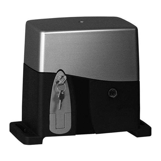
Art. ES82
Art. ES88
ATTUATORE PER CANCELLI SCORREVOLI CON ANTE DA 1200 KG E 1800 KG.
ACTUATOR FOR SLIDING GATES WITH GATE LEAF WEIGHING 1200 KG AND 1800 KG
ACTIONNEUR POUR PORTAILS COULISSANTS AVEC VANTAUX DE 1200 KG ET 1800 KG
MANUALE PER IL COLLEGAMENTO E L'USO - INSTALLATION AND OPERATION MANUAL - MANUEL POUR LA CONNEXION ET L'EMPLOI
Il prodotto è conforme alla direttiva europea 2004/108/CE, 2006/95/CE e successive.
Product is according to EC Directive 2004/108/CE, 2006/95/CE and following norms.
Le produit est conforme à la directive européenne 2004/108/CE, 2006/95/CE et suivantes.
I
Cod. S6I.ES8.200
GB
RL.01
F
9/2012
Advertisement
Table of Contents

Subscribe to Our Youtube Channel
Related Manuals for Elvox ES82


Summary of Contents for Elvox ES82
- Page 1 Art. ES82 Art. ES88 ATTUATORE PER CANCELLI SCORREVOLI CON ANTE DA 1200 KG E 1800 KG. ACTUATOR FOR SLIDING GATES WITH GATE LEAF WEIGHING 1200 KG AND 1800 KG ACTIONNEUR POUR PORTAILS COULISSANTS AVEC VANTAUX DE 1200 KG ET 1800 KG MANUALE PER IL COLLEGAMENTO E L’USO - INSTALLATION AND OPERATION MANUAL - MANUEL POUR LA CONNEXION ET L’EMPLOI...
- Page 2 (au moyen d'une plaque appropriée) qu'ils barriera che sono comandati a distanza mediante ap- ELVOX S.p.A. will not accept liability for any damage sont gérés à distance. posito cartello. . ELVOX S.p.A. décline toute responsabilité pour des caused by the incorrect installation of devices and/or •...
-
Page 3: Dati Tecnici
DATI TECNICI Contenuto dell’imballo: - Motoriduttore - Kit accessori finecorsa - Coppia di chiavi sblocco - Piastra di fissaggio - Condensatore (230vca) DATI TECNICI ES82 ES88 Peso Max anta 1200 Kg 1800 Kg Alimentazione motore 230 Vac 230Vac Assorbimento medio motore... -
Page 4: Collegamento Tipo E Sezione Cavi
COLLEGAMENTO TIPO E SEZIONE CAVI COLLEGAMENTO TIPO E SEZIONE CAVI Lampeggiante Art. ELA2/ELA3 MOTORE CON ELETTRONICA INCORPORATA 2x0,75 mm Tx Fotocellula Rx Fotocellula Fotocellule 4x0,75 mm Art. EFA1 2x0,75 mm Selettore 4x0,75 mm EDS1 3x1,5 mm Linea 230V MODALITA’ D’INSTALLAZIONE Prima di procedere al montaggio dell’automatismo, si verifichi che il cancello sia perfettamente funzionante, Inoltre, è... -
Page 5: Procedura Per L'installazione
MODALITA’ D’INSTALLAZIONE Verificare che le ruote (V. Fig. 4) utilizzate, siano idonee al tipo di guida a terra. PROCEDURA PER L’INSTALLAZIONE Stabilire la posizione dove installare il motoriduttore Posizionare la piastra in dotazione (Fig. 5) ad una distanza di 50 mm dal bordo del cancello e perfettamente in squadro con un’an- golo di 90°. - Page 6 MODALITA’ D’INSTALLAZIONE Fissare le piastre (Camme G) di Fine Corsa del motore sulla cremagliera, (Fig. 8). Fig. 8 Procedura di sblocco 1- Inserire la chiave in dotazione nell’apposito cilindro e ruotare la chiave. 2- Tirare la leva fino a battuta Fig.
- Page 7 SCHEDA EC40/T COLLEGAMENTI EC40/T Lampeggiante Art. ELA2 24V max. 5W Lampeggiante Art. ELA3 230Vc.a. max. 40W 7/36...
-
Page 8: Caratteristiche Generali
CARATTERISTICHE GENERALI CARATTERISTICHE GENERALI L’apparecchiatura EC40 è stata progettata per controllare il funzionamento di attuatori elettromeccanici a 230 V AC, per l’automazione di cancelli ad ante scorrevoli. Ogni altro uso è da considerarsi improprio e quindi pericoloso. È vietato utilizzare il prodotto per scopi diversi da quelli previsti o impropri. È... - Page 9 PROGRAMMAZIONE PROGRAMMAZIONE Durante la procedura di apprendimento, oltre a memorizzare gli spazi di rallentamento e la corsa di apertura pedonale l'apparecchiatura rileva l'eventuale presenza del rilevatore di posizione encoder. 4.1 Procedura di apprendimento per cancello scorrevole Chiudere completamente il cancello. Premere il pulsante di apprendimento P1 per almeno 3 secondi Il led PROG comincia a lampeggiare Rilasciare il pulsante P1...
- Page 10 PROGRAMMAZIONE Se DIP21=ON l'apparecchiatura funziona in modalità Apri-Chiudi. In tal caso: AUTOMATICA CONDOMINIALE, SUPER AUTOMATICA, AUTOMATICA: un impulso di APRI comanda sempre un apertura, un impulso di CHIUDI una chiusura; Una volta aperto, il cancello rimane in pausa per il tempo di sosta.
- Page 11 PROGRAMMAZIONE TRIMMER TR1-PAUSA: regola il tempo di sosta del cancello prima della chiusura nelle logiche automatica, superautomatica e automatica condominiale. TR2-FORZA: regola la coppia del motore. Per motori con frizione oleodinamica o meccanica bisogna regolare il trimmer al MASSIMO. TR3-FRENO: regola l’intensità...
-
Page 12: Manutenzione
MANUTENZIONE MANUTENZIONE • Per garantire l'efficienza del prodotto è indispensabile che personale professionalmente competente effettui la manutenzione nei tempi prestabiliti dall'installatore, dal produttore e della legislazione vigente. • Gli interventi di installazione, manutenzione, riparazione e pulizia devono essere documentati. Tale documentazione deve essere conser- vata dall'utilizzatore, a disposizione del personale competente preposto. -
Page 13: Inconvenienti-Cause E Soluzioni
99/44/CE riguardo la garanzia legale ed è regolata dal D.L. n. 24 del 02.02.2002 pubblicato sulla G.U. n. 57 del 08.05.2002. 2) La garanzia dei prodotti ELVOX è di 24 mesi dalla data di acquisto e comprende la riparazione con sostituzione gratuita delle parti che presentano difetti o vizi di materiale. -
Page 14: Technical Data
TECHNICAL DATA Packaging contents: - Gearmotor - Limit switch accessories kit - Pair of release keys - Fixing plate - Condenser (230 Vac) TECHNICAL DATA ES82 ES88 Max leaf weight 1200 kg 1800 kg Motor power supply 230 Vac 230 Vac Average motor consumption 1.7 A... - Page 15 WIRING TYPE AND CABLE SECTION WIRING TYPE AND CABLE SECTION Flashing light Art. ELA2/ELA3 MOTOR WITH INCORPORATED ELECTRONICS 2x0,75 mm TX photocell RX photocell Photocell 4x0,75 mm Art. EFA1 2x0,75 mm Keyswitch 4x0,75 mm EDS1 3x1,5 mm Line 230V INSTALLATION METHOD Before fitting the automation system, make sue the gate is in perfect working order.
-
Page 16: Installation Procedure
INSTALLATION Make sure the wheels (see Fig.4) used are suited to the runners on the ground. INSTALLATION PROCEDURE Identify the gearmotor installation position. Position the plate supplied (Fig.5) no further than 35 mm away from the edge of the gate, making sure it is perfectly square, at an angle of 90°. - Page 17 INSTALLATION Fix the plates (Cams G) for the motor limit switches to the rack (Fig.8). Fig. 8 Release procedure 1- Insert the key supplied into the relevant cylinder and turn the key. 2- Pull the lever as far as it will go. Fig.
- Page 18 EC40/T CONNECTIONS EC40/T CONNECTIONS Flashing light Art. ELA2 24V max. 5W Flashing light Art. ELA3 230Vc.a. max. 40W Mains power supply 18/36...
-
Page 19: General Characteristics
GENERAL CHARACTERISTICS GENERAL CHARACTERISTICS The EC40 equipment has been designed to control the operation of 230 V AC electromechanical actuators for the automation of swing gates. Any other use is to be considered improper and therefore hazardous. It is prohibited to use the product for an improper purpose or for any purpose other than its intended use. It is prohibited to tamper with or modify the product. - Page 20 GENERAL CHARACTERISTICS PROGRAMMING During the learning procedure, in addition to memorising deceleration spaces and pedestrian opening travel, the system detects any en- coder position detectors present. 4.1 Learning procedure for sliding gates Close the gate fully Press and hold learning pushbutton P1 for at least 3 seconds The PROG LED begins to flash Release pushbutton P1 Press APCH: the gate opens at normal speed...
-
Page 21: Dip Switch
PROGRAMMING If DIP21 = ON the device functions in Open-Close mode. In this case: APARTMENT BLOCK AUTOMATIC, SUPER AUTOMATIC, AUTOMATIC: an OPEN pulse always results in opening and a CLOSE pulse in closing; once open, the gate remains paused for the specified pause time. - Page 22 PROGRAMMING TRIMMER TR1-PAUSE: adjusts the pause time of the gate before it closes in automatic, superautomatic and automatic for apartment block logic systems. TR2-THRUST: adjusts the motor torque. For motors with hydraulic or mechanical clutch, the trimmer must be set to MAXIMUM. TR3-BRAKE: adjusts the braking intensity of the motor during stopping phases.
-
Page 23: Maintenance
MAINTENANCE MAINTENANCE • To ensure the efficiency of the product it is imperative that competent, professional personnel carry out maintenance within the time li- mits established by the installer, the manufacturer and the legislation in force. • Maintenance activities, repairs and replacement of parts must be duly documented. The documentation must be kept by the user so that it is available for the relevant competent personnel. - Page 24 99/44/CE as far as the legal guarantee is concerned and is ruled by the D.L. n. 24 dated 02.02.2002 published in G.U. 57 dated 18.05.2002. 2) The ELVOX product guarantee lasts 24 months from the purchase date and includes the repair with free replacement of parts with de- fects or material vices.
-
Page 25: Données Techniques
Contenu de l'emballage : - Moto-réducteur - Kit d'accessoires fin de course - Paire de clés déblocage - Plaque de fixation - Condensateur (230 Vca) DONNÉES TECHNIQUES ES82 ES88 Poids max. vantail 1200 kg 1800 kg Alimentation moteur 230 Vca... - Page 26 RACCORDEMENT TYPE ET SECTION DES CÂBLES RACCORDEMENT TYPE ET SECTION DES CÂBLES Clignotant Art. ELA2/ELA3 MOTEUR AVEC ÉLECTRONIQUE INCORPORÉE 2x0,75 mm TX photocellule RX photocellule Photocellule Art. EFA1 4x0,75 mm 2x0,75 mm Sélecteur 4x0,75 mm EDS1 3x1,5 mm Ligne 230V MODE D'INSTALLATION Avant de procéder au montage de l'automatisme, il faut vérifier si le portail fonctionne parfaitement.
-
Page 27: Mode D'installation
MODE D'INSTALLATION Vérifier que les roues utilisées (Voir Fig.4) conviennent parfaitement au type de guide au sol. INSTRUCTIONS D'INSTALLATION Choisir l'endroit où le moto-réducteur devra être installé. Placer la plaque fournie (Fig.5) à une distance maximum de 35 mm par rapport au bord du portail et parfaitement à angle droit à 90°. Avant de fixer la plaque avec du ciment, des chevilles ou tout autre système, faire passer la/les gaine(s) des câbles à... - Page 28 MODE D'INSTALLATION Fixer les plaques (cames G) de fin de course du moteur sur la crémaillère (Fig.8). Fig. 8 Procédure de déblocage 1- Introduire la clé fournie dans le cylindre prévu à cet effet et tourner la clé. 2- Tirer le levier à fond Fig.
- Page 29 CONNEXIONS EC40 CONNEXIONS EC40/T Clignotant Art. ELA2 24V max. 5W Clignotant Art. ELA3 230Vc.a. max. 40W Alimentation réseau 29/36...
-
Page 30: Caractéristiques Générales
CARACTÉRISTIQUES GÉNÉRALES CARACTÉRISTIQUES GÉNÉRALES L’appareil EC40 a été conçu pour contrôler le fonctionnement d'actionneurs électromécaniques de 230 V CA pour l'automatisation de portail à vantaux battants. Tout autre utilisation sera considérée comme impropre et, par conséquent, dangereuse. Il est interdit d'utiliser l’appareil dans des buts différents de ceux prévus ou impropres. Il est interdit de manipuler ou de modifier l'appareil. - Page 31 CARACTÉRISTIQUES GÉNÉRALES PROGRAMMATION Pendant la procédure d'apprentissage, l'appareil non seulement mémorise les espaces de ralentissement et la course d'ouverture piétonne mais détecte également l'éventuelle présence du détecteur de position codeur. 4.1 Procédure d'apprentissage pour portail coulissant Fermer complètement le portail. Appuyer sur le bouton d'apprentissage P1 pendant au moins 3 secondes.
- Page 32 PROGRAMMATEUR Si DIP21=ON, l'appareil fonctionne en mode Ouvrir-Fermer. Dans ce cas : AUTOMATIQUE COPROPRIÉTÉ, SUPER AUTOMATIQUE, AUTOMATIQUE : une impulsion sur OUVRIR commande toujours une ouverture, un impulsion sur FERMER une fermeture ; Une fois ouvert, le portail reste en pause pour le temps d'arrêt. Une impulsion sur FERMER pendant la pause commande la fermeture. La fonction courtoisie, si prévue, reste active.
- Page 33 PROGRAMMATEUR TRIMMER TR1-PAUSE : règle le temps de pause du portail avant la fermeture dans les logiques automatique, super-automatique et automatique copropriété. TR2-FORCE : règle le couple du moteur. Pour les moteurs à embrayage hydraulique ou mécanique, il faut régler le trimmer sur le MAXI- MUM.
- Page 34 MAINTENANCE MAINTENANCE • Pour garantir l'efficacité de l'appareil, il est indispensable que le personnel compétent effectue la maintenance dans les délais prééta- blis par l'installateur, par le fabricant et la règlementation en vigueur. • Les interventions d'installation, de maintenance, de réparation et de nettoyage doivent être documentées. Cette documentation doit être conservée par l'utilisateur et mis à...
- Page 35 99/44/CE concernant la garantie légale et est réglée par le D.L. n. 24 de 02.02.2002 publié sur la G.U. n. 57 de 08.05.2002. 2) La garantie des produits ELVOX est de 24 mois à partir de la date d’achat et comprend la réparation avec substitution gratuite des par- ties qui présentent des défets ou vices de matériel.
- Page 36 TIMBRE DE L’INSTALLATEUR DATE DE L’INSTALLATION Riproduzione vietata anche parziale. La società ELVOX s.p.a. tutela i diritti sui propri elaborati a termine di Legge. Reproduction forbidden, even partial. ELVOX S.P.A. guards its own rights according to the law. Réproduction défendu, même partiale. La Société ELVOX S.P.A. defende ses droits selon la loi.
Need help?
Do you have a question about the ES82 and is the answer not in the manual?
Questions and answers