Advertisement
Quick Links
Advertisement

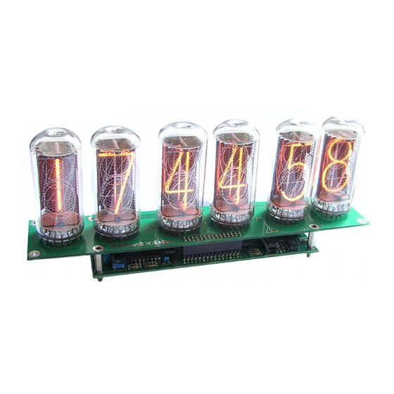
Summary of Contents for TUBEHOBBY Nixie Clock NCV2.1
- Page 1 NCV2.1 Nixie Clock User's guide Firmware version: v1.3...
- Page 2 1 Safety instructions Nixie clock is an electrical device and cautious handling must be assured. In spite of the relatively low voltage board power supply, a high voltage is present onboard. It can generate voltages exceeding 200V and can cause electrical shock if handled inappropriately. Keep in mind that nixie tubes may be disabled during night time but the clock can wake up at any time.
- Page 3 Fig. 2. Logic board Table 1. Logic board's part's list. Item Quantity Reference Part Capacitors 470U C3, C5 C4, C8, C9 1U 250V 330N Diodes 1N4007 UF4007 D3, D4 1N4148 Transistors IRF640 Q1, Q2, Q3, Q7, Q9 MPSA42 2SA1266 Q5, Q6, Q8 MPSA92 Resistors R15, R17, R18, R19, R20,...
- Page 4 Integrated circuits L7805CV U2, U3 K155ID1 PIC16F876A TL494 DS1307 Other components CR2032 3V Lithium Battery Crystal 20MHZ Crystal 32.768KHz SW1, SW2 PUSHBUTTON 270UH FUSE 0.8A PS/2 Connector PWR Connector Battery holder 30Pin Connector Fuse holder M3 Nut M3 Screw 20mm spacer *2.2K resistors are provided along with the kit for IN-18 tubes instead of appropriate amount of 10K resistors.
- Page 5 Find #1 pin of the tube. It is covered by the white substance inside the tube. Fig. 4. Pin #1 Pin #1 on the PCB is the most upper pin. Fig. 5. Pin #1 on PCB...
- Page 6 Insert the wires into the holes. Start from Pin #1. Be sure that the tubes are stacked on the right side of the PCB. Fig. 6. Tube assembling Stack and solder all the tubes in the same way. Then fit the female 30-pin connector on the opposite side of the PCB.
- Page 7 2.2.2 IN-18 board Put all 72 receptacles into the tube's board holes. Fig. 8. Fitting receptacles Note: pin #1 and pin #8 of each tube do not require receptacles since these pins are not connected. Make sure that receptacles are fitted on the right side of the PCB. After all receptacles are placed correctly, cover the board with a piece of hard paper and turn everything upside-down.
- Page 8 While soldering keep the PCB slightly pressed to ensure firm sitting of the receptacles. Do not use too much solder. Fig. 10. Soldering Fit the female 30 pin socket on the bottom side. Fit the column separator bulbs if you prefer to have them.
- Page 9 NOTE: In order to update the firmware of your clock please send the PICmicro chip or whole logic board back to us for re-flashing, or order preprogrammed chip. Please contact us by email: info@tubehobby.com 3.2 Clock’s menu NCV2.1 nixie clock has 2 pushbuttons. There are 4 different behaviors pushing them: short and long push for each button.
- Page 10 When the clock is powered it automatically enters the time state. A short push of SW1 pushbutton will change the time state into the date state. Next short push of any button will return to the time state again. A short push of SW2 pushbutton will change the time state to the tube's lifetime counter state.
- Page 11 3.4 Setting date Short push to SW1 to enter the date state. There are two date display modes: DD/MM/YY and MM/DD/YY. A long push to SW2 will toggle between these modes. To set date, push and hold SW1 while date is displayed. After 3 seconds day will start blinking. A short push to SW2 will increase the day by 1, a long push to SW2 will decrease by 1.
- Page 12 Tube’s Lifetime DST Vernal Hour Format Counter Hour 12/24 To 1 branch Time State DST Vernal Leading Zero Weekday DST Vernal Column Separator Week Mode DST Vernal Autorotate Date Month DST Autumnal Reset Tube’s Hour Lifetime Counter DST Autumnal Night Shut-Down Weekday Minutes DST Autumnal...
- Page 13 3.5 Tube's lifetime counter The tube's lifetime counter counts hours when the tubes are lit. During the night shut-down (if enabled) hours are not taken into account. Counter counts until 65535 hours, then overflow occurs and counter will start again from zero. To enter the tube's lifetime counter press SW2 when time is shown.
- Page 14 ● Mode 01. Auto rotate is enabled Default mode: enabled (in firmware v1.0 and v1.1 default mode - disabled). 3.6.5 Reset tube's lifetime counter (5) To reset the tube's lifetime counter press SW2. When the counter is reset, 00 will appear on the most right tubes.
- Page 15 3.6.11 DST vernal hour (11) The clock can automatically adjust time according to your local daylight saving time (DST). Since the beginning of DST and reverting to the standard time varies across the world, you should set it accordingly to your local country rules. On the vernal change the clock is turned forward an hour and on the autumnal change reverted back.
- Page 16 3.6.18 DST autumnal month (18) Set the DST autumnal month using SW2. The month is shown on the most right tubes. Default month – 10 (october). 3.6.19 Crossfading deep (19) The clock can fade one digit while simultaneously fading into a second digit creating smooth appearance of digit change.
- Page 17 Fig. 14. GPS receiver A GPS receiver should be NMEA-0183 standard compatible and should be able to provide GPRMC sentences via RS232 interface at 4800 baud. A required PS/2 type connector usually is used with the receivers for PDAs. Compatible receivers are: “NAVILOCK NL-208P”, “HAICOM HI-204III” and many others.
- Page 18 4.1.1 Technical data 4.2 Software ● Time display ■ 12-hour mode ■ 24-hour mode ■ AM/PM indication ■ Programmable leading zero suppression ■ Programmable DST correction ● Date display ■ DD/MM/YY mode ■ MM/DD/YY mode ■ Leap year correction ● Programmable column separators ●...
- Page 19 High Voltage Drivers High Voltage Drivers Size Size Size Document Number Document Number Document Number NCV2, Copyright 2006, TubeHobby NCV2, Copyright 2006, TubeHobby NCV2, Copyright 2006, TubeHobby Date: Date: Date: Saturday, April 22, 2006 Saturday, April 22, 2006 Saturday, April 22, 2006...
- Page 20 Microcontroller Unit Microcontroller Unit Size Size Size Document Number Document Number Document Number NCV2, Copyright 2006, TubeHobby NCV2, Copyright 2006, TubeHobby NCV2, Copyright 2006, TubeHobby Date: Date: Date: Saturday, April 22, 2006 Saturday, April 22, 2006 Saturday, April 22, 2006...
- Page 21 Power supply Power supply Size Size Size Document Number Document Number Document Number NCV2, Copyright 2006, TubeHobby NCV2, Copyright 2006, TubeHobby NCV2, Copyright 2006, TubeHobby Date: Date: Date: Sunday, July 30, 2006 Sunday, July 30, 2006 Sunday, July 30, 2006...
- Page 22 Peripheral Peripheral Peripheral Size Size Size Document Number Document Number Document Number NCV2, Copyright 2006, TubeHobby NCV2, Copyright 2006, TubeHobby NCV2, Copyright 2006, TubeHobby Date: Date: Date: Sunday, July 30, 2006 Sunday, July 30, 2006 Sunday, July 30, 2006 Sheet...
- Page 23 IN-14 Tube's Board IN-14 Tube's Board Size Size Size Document Number Document Number Document Number NCV2, Copyright 2006, TubeHobby NCV2, Copyright 2006, TubeHobby NCV2, Copyright 2006, TubeHobby Date: Date: Date: Monday, December 13, 2010 Monday, December 13, 2010 Monday, December 13, 2010...
- Page 28 Gas discharge indicator type IN-14 (ИН-14) Datasheet translated by TubeHobby www.tubehobby.com Description Gas discharge indicator is intended for visual indication of electrical signals in digital form in broad kind of equipment. Connection diagram Description number Anode Cathode comma Cathode “1”...
-
Page 29: Allowable Limits
Basic electrical and lighting parameters Firing voltage (no more than) 170V Current for digits (no more than) 2.5mA Current for commas (no more than) 0.3mA Brightness (no less than) 100 cd/m² Viewing angle (no less than) +/- 30º Allowable limits Power supply voltage 200V Current for digits...
Need help?
Do you have a question about the Nixie Clock NCV2.1 and is the answer not in the manual?
Questions and answers