Table of Contents
Advertisement
Advertisement
Table of Contents

Summary of Contents for DECODE IDM 50B
- Page 1 DECODE Multi-standard modem IDM 50B User Manual v1.2n http://www.decode.co.yu...
-
Page 2: Modem Overview
INTRODUCTION 1.1 Modem Overview IDM50B is a multistandard modem for asynchronous or transparent data transmission in 300- 3400 Hz voice band. For lower baud rates it uses binary frequency modulation techniques (FSK), which make it highly immune to interference and noise and permit extensive voice-band communication link utilization. -
Page 3: Front Panel
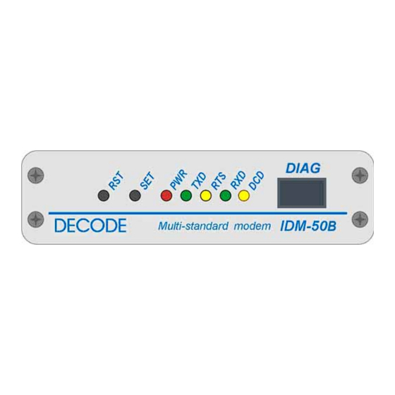
Data Carrier Detect LED indicates the presence of in-channel carrier with level higher then predefined receive level. Figure 2. IDM 50B Front panel view (desktop version) 2.1.1 DIAG – Command/Bootloader serial interface This connector is a RJ45 8 pin female type connector. It provides the interface between the modem and terminal unit in command mode and in firmware upgrade process. -
Page 4: Rear Panel Connectors
2.2 Rear panel connectors Three connectors are placed at the modem’s rear side (Fig. 3). Figure 3. IDM 50B rear side (desktop version) 2.2.1 RS-232C / Data serial interface This connector is a SUB D 9 pin female type connector with screw locking. It provides the interface between the modem and remote terminal unit or data processing equipment in data mode. - Page 5 2.2.2 Line / Analog interface This connector is a SUB D 15 pin female type connector with screw locking, which provides: Interface between 2 or 4 wire analog line and the modem; The fail relay output On the same connector modem has interface intended for communications management with a radio interface (squelch and alternate) which are not supported in current firmware version.
-
Page 6: Hardware Configuration
HARDWARE CONFIGURATION Hardware configuration is performed directly on the modem board by positioning the jumpers according to the figure and the table below: Figure 5. Jumper placement on the modem board 3.1 Jumpers placement (bold fase denotes factory default placement) Feature Jumpers Option... - Page 7 Feature Jumpers Option Jumpers Placement Alternate radio JP407, Proceed alternate radio relay signals JP407 relay signal ALT1 and ALT2 to connector JP409 JP409 presence on Do not proceed alternate radio relay JP407 connector signals ALT1 and ALT2 to connector JP409 Fail relay signal JP411, Proceed fail relay signals DEF1 and...
-
Page 8: Software Configuration
If modem is already turned on, push the SET button, then push and release the RESET button while keeping the SET button pushed approximately for 1 second. 3. Modem will respond with its introductory message “IDM 50B LS vx.x” indicating command mode and firmware version. -
Page 9: Commands Description
4.3 Commands Description Operational Mode Sets FSK or CCITT V.29 operational modes. Valid values for x are: AT & Mx x = 0 FSK mode where Zin/out=600Ω x = 1 FSK/MUX1 mode where Zin=10k and Zout=600Ω x = 2 FSK/MUX2 mode where Zin=600Ω/10k and Zout=10k x = 3 V.29 mode, 4800bps x = 4... - Page 10 Receive Channel in FSK mode Sets CCITT V.23/1 and V.23/2 channels for data reception. Valid AT &R C 23 / y range for y is 1, 2 corresponding to V23/0 and V.23/1 at 600Bd, and V.23/2 at 1200Bd channels, respectively. Sets Cegelec 1200Bd 701 channel for data reception.
- Page 11 carrier and DCD signal) with a hysteresis of 3 dB (detection of carrier and DCD signal at R – 9 dB). The minimum reception level is –48 dBm. Example: AT&RL27 command line sets receive level at –27dBm. Modem responds with “OK” message. Serial Interface Mode Sets serial interface mode.
-
Page 12: Character Format
Carrier control Selects transmission carrier control mode. For x=0 transmission is AT &C C x always on and carrier is permanent. For x = 1 transmission is active only if RTS = 1 (Data Terminal Equipment requires to send). For x = 2 transmission is active only if there is data in transmission buffer. -
Page 13: Display Modem Info
Display Modem Info Displays full modem info (manufacturer, model, type, firmware version and date) in following format: “DECODE IDM 50B LS vx.x dd/mm/yy”. IDM50B User Manual v1.2n, Rev. date: 24 februar, 2009... -
Page 14: Test Modes
4.4 Test modes IDM 50 modem provides on-line test and control functions, such as remote feedback looping and the transmission of test sequences, thus making possible to measure in-channel signal level and count bit errors. This possibilities considerably improve commissioning and maintenance of telecommunications links. - Page 15 REMOTE TESTS – This feature makes possible to perform testing of remote modems, in FSK mode, on point-to point and multipoint links with selective addressing of the remote modem. Every modem, when is in data mode, search received data for remote loop-back command pattern with its own (local) address.
- Page 16 Example: AT&TST9 ENTER TEST MODE 9 EXIT TEST MODE TEST STATUS: OK RX LEVEL: -5dBm ELAPSED SEC: 00000175 BIT COUNT: 00033704 ERROR COUNT: 00000000 LOOPBACK MODE – This feature enable loopback at digital interface when SET switch at the front panel is pressed. This state is indicated by slow PWR led blink (1sec / 1sec cycle). Modem performs the same task as it have received remote loopback pattern.
-
Page 17: Firmware Upgrade
IDM-50B has an ability to be upgraded with new firmware in the field by performing bootloading procedure. Latest version of IDM50B firmware may be found and downloaded at no charge from Decode web site http://www.decode.rs. 5.1 Bootloading Procedure Important: Before starting with bootloading procedure make sure that modem jumper JP300 is in factory settings position 1-2 (EXT_BSL). - Page 18 4. Connect IDM50B bootloader adapter cable (delivered as additional accesory) at IDM50B RJ45 DIAG RS-232 port. Make sure that cable switch is at RUN position. 5. Connect avaliable PC serial COM port and bootloader adapter cable with RS-232 communication cable (delivered as additi onal accesory).
- Page 19 APPENDIX A 1. IDM 50B Rack 1U (up to 3 modems) igure A1a. Rack frame 1U/84TE - Front view Figure A1b. Rack frame 1U/84TE - Rear view igure A1c. Rack frame 1U/84TE - Side view 172.5 igure A1d. Rack 1U/28TE - Front plate view igure A1e.
- Page 20 A2. IDM 50B Rack 3U (up to 14 modems) Figure A2a. Rack frame 3U/84TE - Front view DECODE DECODE DECODE DECODE DECODE DECODE DECODE DECODE DECODE DECODE DECODE DECODE DECODE DECODE 84 TE 482,6 Figure A2b. Rack frame 3U/84TE - Rear view 172.5...
- Page 21 A3. IDM 50B Desktop Figure A3a. Front view Figure A3b. Rear view Line RS-232C Power DECODE data communications www.decode.co.yu Figure A3c. Top view IDM50B User Manual v1.2n, Rev. date: 24 februar, 2009...
- Page 22 APPENDIX B DIAG serial port adapter cable This adapter cable is designed to be plugged in RJ45 front DIAG RS232 serial port at IDM50B modem, providing standard DB9F DCE pinout on the other side of cable. DIAG port, equiped with this cable, is used for setting IDM50B modem parameters with AT commands, when switch is in RUN position, and for upgrading firmware using bootloader mode, when switch is in BSL position.
- Page 23 APPENDIX C FSK channels and frequencies table FSK Channel -F [Hz] F0 [Hz] +F [Hz] V23/0 600bd 2650 2850 3050 V23/1 600bd 1300 1500 1700 V23/2 1200bd 1300 1700 2100 CH701 1320 1800 2280 CH601 1080 CH602 1560 1800 2040 CH603 2520 2760...
Need help?
Do you have a question about the IDM 50B and is the answer not in the manual?
Questions and answers