Table of Contents
Advertisement
Quick Links
Advertisement
Table of Contents

Subscribe to Our Youtube Channel
Related Manuals for TKR Group PNP 90 UN 2.0

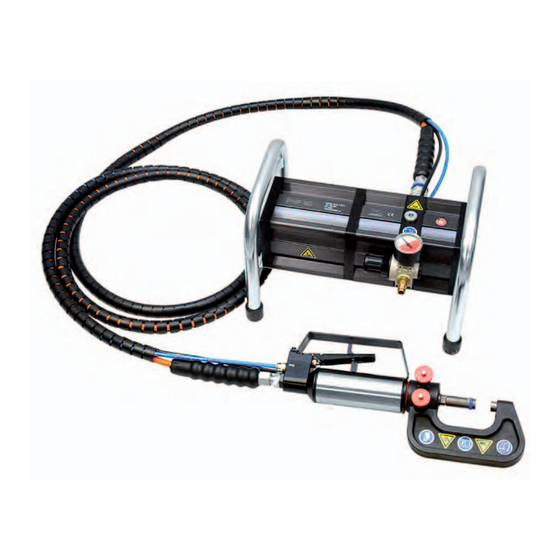
Summary of Contents for TKR Group PNP 90 UN 2.0
- Page 1 Pneumatic, hydraulic Universal Riveting Tool PNP 90 UN 2.0 Instruction manual...
-
Page 2: Table Of Contents
3. Designations 1. Operating principles 2. Scope of Supply and Accessories 3. Safety instructions 4. Principles for Handling the Tool Kit PNP 90 UN 2.0 5. Maintenance 6. Warranty 1. Technical Data Pump PNP 90 UN 2.0 2. Technical Data Hydraulic Actuator HP 35 UN 3. -
Page 3: Information Regarding This Manual
1.1 Information regarding this manual Information Handling Legislation stipulates that workers handling hydraulically- All handling necessary to ensure correct operation is driven riveting tools must be protected. If desired, trai- described in the instruction manual. No work method ning can be provided at TKR in Gevelsberg or on site at other than that expressly approved by the manufacturer the customer. -
Page 4: Designations
1.3 Designations Designations on the stamping and riveting tool 1.3.1 Type designation Serial number Manufacturer‘s designation, production date Maximum permissible operating pressure (oil) CE mark Symbol to read the instruction manual 2.1 Operating principles The pneumatic/hydraulic universal tool PNP90-UN 2.0 The two pneumatic control lines are also connected to was specially developed for all common riveting opera- the pump. -
Page 5: Scope Of Supply And Accessories
2.2 Scope of Supply and Accessories Scope of supply basic kit PNP 90 UN 2.0 Accessories (not part of the basic kit) 1x Pressure intensifier PNP 90 1x Rivet clamp NB 115 1x Hydraulic actuator HP 35 UN 1x Rivet clamp NB 230 1x Rivet clamp NB 40 1x Pop rivet adaptor RIVPULL 2.0**... -
Page 6: Safety Instructions
2.3 Safety instructions The hydraulic tool kit is strictly approved only Protective gloves and a face mask must strictly for the purposes intended by the manufacturer. be worn for all applications of the equipment, because metallic parts can break up and fly Only genuine accessories may be used. -
Page 7: Principles For Handling The Tool Kit Pnp 90 Un
Before starting work, check the preset air pressure! Incorrectly set air pressure could Declaration of Conformity cause equipment damage or physical injury! Riveting tool PNP 90 UN 2.0 has been tested and manufactured in accordance with European Max. air pressure guidelines. The Declaration of Conformity has Make sure that the maximum permissible ope- been included with this instruction manual. -
Page 8: Maintenance
2.5 Maintenance The tool‘s hydraulic system, pneumatic Oil that is not properly disposed of could control sys tems, hoses and couplings harm the environment. must all be kept free of dirt and other contamination. Foreign bodies in the hy- The user must only perform the maintenance draulic fluid or in the control air can cau- and repair measures outlined in this instruction se the tool system to malfunction. -
Page 9: Warranty
2.6 Warranty Stamping and riveting tools from TKR Automotive GmbH come with a 12-month war- ranty against material and manufacturing defects. This does not cover wearing parts (rivet mandrels, rivet dies, spacing bolts and spacing sleeves) or hydraulic oil. The warranty period begins on the date of delivery, as specified on the invoice or de- livery note. -
Page 10: Technical Data Pump Pnp 90 Un
3.1 Technical Data Pump PNP 90 UN 2.0 3.1.1 3.1.2 Pump PNP 90 UN 2.0 3.1.3 Length 330 mm Width 230 mm Height (incl handle) 213 mm Weight 8 kg Max. input pressure 5.5 bar Max. operating pressure 550 bar 3.2 Technical Data Hydraulic Actuator HP 35 UN... -
Page 11: Technical Data Riveting Tool Kit Rivkit Un
3.3 Technical Data Riveting Tool Kit RIVKIT UN 2.0 3.3.1 WZS-TKR-00000024 Riveting Tool Kit RIVKIT UN 2.0 Kit number Item/Description/Article number Item/Description/Article number A Setting head, 3 mm rivet B Closing head, 3 mm rivet Kit: BGR-TKR- 00000024 BGR-TKR-00000244 01-00000707 C Setting head, 5 mm rivet D Closing head, 5 mm rivet Kit: BGR-TKR-... -
Page 12: Technical Data Rivet Clamp
3.4 Technical Data Rivet Clamp 3.4.1 3.4.2 Rivet clamp NB 40 3.4.3 3.4.4 3.4.5 Rivet clamp NB 115 3.4.6... - Page 13 3.4.7 3.4.8 364.1 44.5 364.1 364.1 44.5 44.5 Rivet clamp NB 230 3.4.9 Technical data Rivet clamp NB 40 Rivet clamp NB 115 Rivet clamp NB 230 Article number 05-00000026 05-00000031 05-00000027 Length* 106 mm 213 mm 364.1 mm Width 45 mm 44 mm 44.5 mm...
-
Page 14: Startup
4.1 Startup 4.1.1 4.1.2 G1/4“ 4.1.3 4.1.4 R1/4“ The equipment is supplied from the factory without a compressed air connection. The pressure regulator has a G1/4“ (internal thread) connection thread. 4.1.1/4.1.2 The pressure regulator is supplied with a closing cap fit- ted. -
Page 15: Riveting Tool Preparation And Connection Of The Hydraulic Actuator
4.2 Riveting Tool Preparation and Connection of the Hydraulic Actuator 4.2.1 4.2.2 4.2.3 4.2.4 4.2.5 4.2.5 Connect the pneumatic hoses. Make sure that the black hose is attached to the marked coupling. Before using the equipment, check the condition of the hydraulic actuator with add-on component and hoses. - Page 16 4.2 Riveting Tool Preparation and Connection of the Hydraulic Actuator 4.2.7 4.2.8 max. 6 bar / 87 psi 4.2.7 Connect compressed air to the pressure regulating valve and set the pressure. 4.2.8 Never use pressure over the permitted va- lue of 6 bar or 87 psi. This could cause damage to the equipment or even physical injury.
-
Page 17: Safe Set-Up And Positioning Of Equipment
4.3 Safe Set-Up and Positioning of Equipment 4.3.1 Ensure that the high-pressure pump is 4.3.2 always placed on a non-slip surface and that the hoses are routed in a way that prevents them from getting damaged or pinched off. The hoses must also be routed in a way that prevents people from tripping over them. -
Page 18: Connecting The Tool To The Hydraulic Actuator
4.4 Connecting the Tool to the Hydraulic Actuator 4.4.1 4.4.2 4.4.1/4.4.2 4.4.3 4.4.4 Select tool and prepare locking pins. The tool is carefully pushed onto the mounting adapter by the mounting hole. The indexing pin in the mounting adaptor must engage in the corresponding slots in the mounting hole. -
Page 19: Riveting Tool Kit Rivkit Un 2.0 - Fitting And Intended Use
4.5 Riveting Tool Kit RIVKIT UN 2.0 – Fitting and Intended Use 4.5.1 4.5.2 Three rivet clamps are currently available for use 4.5.3 with the RIVKIT UN 2.0 riveting tool kit: Rivet clamp Art. No. Opening depth NB 40 05-00000026 up to 40 mm NB 115 05-00000031... -
Page 20: Pressing Out Rivets
5.1 Pressing out Rivets 5.1.2 01-00000788 5.1.3 01-00000784 5.1.1 5.1.4 5.1.5 5.1.6 Old or defective rivets often need to be removed from the sheet metal structure when repairing body panels. 5.1.1 – 5.1.6 To avoid having to drill out these rivets, the olds rivet can be pressed out of the sheet metal structure using the extraction mandrel art. -
Page 21: Punching And Calibration Of Holes For Flow Form Rivets
5.2 Punching and Calibration of Holes for Flow Form Rivets 5.2.1 01-00000922 5.2.2 01-00000923 5.2.3 5.2.1 – 5.2.5 5.2.4 There is no need to drill holes in sheet joints when using flow form rivets. Punch art. no. 01-00000922 and punch die art. -
Page 22: Setting Of Flow Form Rivets
5.3 Setting of Flow Form Rivets 5.3.1 01-00000917 5.3.2 01-00000918 5.3.3 5.3.4 5.3.5 5.3.1, 5.3.2 5.3.6 The flow form rivets are installed using the setting head art. no. 01-00000917 and corresponding closing head art. no. 01-00000918 (kit BGR-TKR-00000048) intended for this purpose. 5.3.3 It is important that the setting head with the centring lug engages into the corresponding depression in the rivet. -
Page 23: Installation Of Semi-Tubular Punch Rivets
5.4 Installation of Semi-Tubular Punch Rivets 5.4.1 BGR-TKR-00000244 5.4.2 01-00000707 5.4.3 BGR-TKR-00000245 5.4.4 01-00000706 Ø 3 mm Ø 3 mm Ø 5 mm Ø 5 mm 5.4.5 5.4.6 5.4.1 – 5.4.4 5.4.7 Extra care must be taken to ensure that the rivets that are used are properly seated when installing semi-tubular punch rivets. -
Page 24: Checking Riveting Results
5.5 Checking Riveting Results 5.5.1 – 5.5.3 5.5.1 5.5.2 The results must be checked after the riveting operation. If the installed rivet does not meet quality requirements, the reason for the fault must be determined. If the quality of the installed rivet is acceptable, the work process can be repeated. -
Page 25: Completing An Operation And Riveting Tool Storage
5.7 Completing an Operation and Riveting Tool Storage 5.7.1 5.7.1 Always disconnect the compressed air supply from the pump after riveting and during work interruptions. 5.7.2 Then disconnect the control hoses and seal the openings. Make sure that the disconnected hoses ne- ver make contact with the dirty floor or the ground. -
Page 26: Hydraulic Pump Maintenance
6.1 Hydraulic pump maintenance 6.1.1 6.1.2 6.1.3 6.1.4... - Page 27 6.1.6 6.1.5 280 ml 6.1.2 – 6.1.4 Draining oil 6.1.7 Undo the sealing plug on the top of the pump and let the used hydraulic fluid flow into a suitable container. 6.1.5, 6.1.6 Filling oil Fill with fresh oil that complies with the specifications. The nominal filling volume is around 280 ccm.
-
Page 29: Replacement Part List
6.2 Replacement Part List Pos.-Nr. Art.-Nr. Titel HYW-TKR-00000010 PNP 90 pressure intensifier (pump) HYW-TKR-00000017 Hydraulic actuator HP 35 UN HAW-TKR-00000121 Ball lock pin 05-00000026 Rivet clamp NB 40 05-00000031 Rivet clamp NB 115 05-00000027 Rivet clamp NB 230 01-00001674 Spacer Pos.-Nr. -
Page 30: Troubleshooting
6.3 Troubleshooting Problem Cause Remedy Page No air connected Connect compressed air Control lines not connected or incor- Connect control lines correctly and make sure rectly connected they are properly seated Insufficient air pressure Check air supply Pump does not Connect hydraulic hose as described in the Hydraulic hose not connected instruction manual... -
Page 31: Declaration Of Conformity
Am Waldesrand 9-11 58285 Gevelsberg, Germany Equipment type: Tool type: Pneumatic/hydraulic stamping and riveting tool Type designation: PNP 90 UN 2.0 Developed and manufactured in accordance with the standards and guidelines listed below by TKR Automotive GmbH Am Waldesrand 9-11... - Page 32 Am Waldesrand 9–11 D-58285 Gevelsberg (Germany) Phone +49 2332 66607-77 +49 2332 66607-51 Email info@tkrgroup.com Internet www.tkrgroup.com...
Need help?
Do you have a question about the PNP 90 UN 2.0 and is the answer not in the manual?
Questions and answers