
Summary of Contents for Dionex ASE 150
- Page 1 ® Accelerated Solvent Extractor Operator's Manual Document No. 065207 Revision 02 September 2008...
- Page 2 HEREINOF WITHOUT OBLIGATION OF DIONEX CORPORATION TO NOTIFY ANY PERSON OR ORGANIZATION OF SUCH REVISION OR CHANGES. TRADEMARKS AutoSeal is a trademark of Dionex Corporation. ASE 150 is a registered trademark of Dionex Corporation. Acrobat, Adobe, and Adobe Reader are registered trademarks of Adobe Systems, Incorporated.
-
Page 3: Table Of Contents
Rear Panel ..........15 ASE 150 Extraction Process ....... . . 16 Method Control . - Page 4 ASE 150 Operator’s Manual 3 • Operation and Maintenance Preparing to Run ......... . .25 3.1.1...
- Page 5 Contents Performing Routine Maintenance ......54 3.8.1 Daily Maintenance ........54 3.8.2 Periodic Maintenance .
- Page 6 ASE 150 Operator’s Manual 5.5.7 Reinstalling the Pump ....... .78 5.5.8...
- Page 7 Contents Sample Cells ..........104 Collection Vessels .
- Page 8 ASE 150 Operator’s Manual Diagnostic Screens ........131 C.2.1...
-
Page 9: Introduction
The ASE 150 can be used with organic solvent, aqueous buffer, water, and small amounts of mineral acids. The ASE 150 accelerates the traditional extraction process by using solvent at elevated temperatures and pressures. -
Page 10: About This Manual
ASE 150 Operator’s Manual The ASE 150 is designed to minimize the amount of solvent used without sacrificing the speed of extraction or ease of operation. Samples are extracted one at a time, and the extraction process is typically completed in 15 to 25 minutes. -
Page 11: Safety Messages And Notes
1.2.2 Safety Messages and Notes This manual contains warnings and precautionary statements that can prevent personal injury and/or damage to the ASE 150 when properly followed. Safety messages appear in bold type and are accompanied by icons, as shown below. - Page 12 ASE 150 Operator’s Manual Signale une situation de danger potentiel qui, si elle n'est pas évitée, pourrait entraîner des blessures graves à mortelles. Signale une situation de danger potentiel qui, si elle n'est pas évitée, pourrait entraîner des blessures mineures à modérées. Également utilisé...
-
Page 13: Safety And Regulatory Information
527 Lakeside Drive, Sunnyvale, CA 94088-3603 U.S.A. The ASE 150 is designed for solvent extraction applications and should not be used for any other purpose. Operation of an ASE 150 in a manner not specified by Dionex may result in personal injury. - Page 14 ASE 150 Operator’s Manual Power supply is on Power supply is off Hot surface Indicates a potential hazard. Refer to the operator’s manual for an explanation of the hazard and how to proceed. Doc. 065207-02 9/08...
-
Page 15: Description
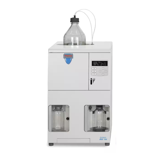
2 • Description Operating Features Figure 2-1 illustrates the main operating features of the ASE 150 Accelerated Solvent Extractor. Solvent Reservoir Sample Cell Oven Control Panel Door OPEN Lever Waste Bottle Needle UP/DOWN Switch Collection Vessel (250-mL bottle shown) Drip Tray Figure 2-1. - Page 16 ASE 150 Operator’s Manual Solvent Reservoir A 2-liter solvent reservoir is installed in a recess on top of the ASE 150. The recess contains a plastic liner that collects any solvent leaks or spills that may occur and directs them through a drain tube to the rear panel. A drain hose connects to the drain tube and is routed to a waste container.
-
Page 17: Control Panel
2.1.1 Control Panel Use the control panel screen and buttons to control ASE 150 operation. The screen displays status and operating information. You can edit any field on the screen that contains a blinking cursor. A field without a blinking cursor is for display only. - Page 18 When the cursor is in an editable field, pressing saves ENTER the parameter currently displayed in the field. Table 2-1. ASE 150 Control Panel Button Functions Doc. 065207-02 9/08...
-
Page 19: Sample Cells And Rinse Cells
Note: Pressing and holding down an arrow button moves the cursor continuously through the allowed settings. Table 2-1. ASE 150 Control Panel Button Functions (Continued) 2.1.2 Sample Cells and Rinse Cells NOTE... - Page 20 To perform a run with a cell in a different size than the size originally ordered, order the cells from Dionex. You will also need to order the Startup Kit appropriate for the new cell size. For cell and Startup Kit part...
-
Page 21: Collection Vessels
2 • Description 2.1.3 Collection Vessels The following collection vessels are available: Collection Vessel Part Number Quantity 60-mL clear vials 048784 Pkg. of 72 60-mL amber vials 048781 Pkg. of 72 60-mL clear graduated vial, Class A 068226 60-mL clear graduated vial, Class B 068248 250-mL clear bottles 056284... -
Page 22: Solvent Reservoir
A vent outlet line is also connected to the waste bottle cap; gas is vented out this line to the rear panel. The ASE 150 Ship Kit (P/N 066399) provides vent tubing (P/N 053514) that you can connect to the vent outlet... -
Page 23: Rear Panel
Section B.2.3. • The model data label lists fuse and power information, as well as the ASE 150 serial number. You will be asked to provide the serial number when ordering replacement parts for the system. • connector is connected to a nitrogen supply regulated to NITROGEN between 0.97 and 1.38 MPa (140 and 200 psi);... -
Page 24: Ase 150 Extraction Process
ASE 150 Operator’s Manual • The drain directs solvent spills from the bottle area on top of the ASE 150 to the rear panel. A drain hose connects to the fitting. For installation instructions, see Section B.2.2. ASE 150 Extraction Process Preparing to Run an Extraction The following steps are required before the ASE 150 can perform an extraction. - Page 25 After you complete the preparation steps described on page 16 and press START the second time, the ASE 150 performs the extraction. The extraction process consists of six main steps. 1. Fill the cell with solvent—the pump is turned on and the...
- Page 26 ASE 150 Operator’s Manual Monitoring the Progress of a Run To monitor the progress of a run, press , move the cursor to MENU STATUS necessary), and press . The screen appears (see Figure 2-5). ENTER STATUS STATUS STATIC 75mL...
-
Page 27: Method Control
2 • Description Method Control A method determines how the ASE 150 performs the sample extraction. Methods are defined on the screen (see Figure 2-6). METHOD EDITOR METHOD TEMPERATURE 100C STATIC TIME 5MIN RINSE VOLUME Figure 2-6. Method Editor Screen (Initial View) The following method parameters define the method. -
Page 28: Preprogrammed Methods
ASE 150 Operator’s Manual Preprogrammed Methods To help you quickly produce results with the ASE 150, Dionex provides nine preprogrammed methods. These methods are designated by three-letter abbreviations (see the table below). Preprogrammed Method Method Name Semivolatiles Total Fat (crude) - Page 29 2 • Description FAT (Total Fat) Method Parameters Solvent Hexane/Acetone (4:1) Temperature 125 °C Static Time 5 min Rinse Volume 100% Purge Time 60 sec Static Cycle Cell Type Stainless steel HRB (Chlorinated Herbicides) Method Parameters Solvent MeCl /Acetone (1:1) with 1% Temperature 100 °C Static Time...
- Page 30 ASE 150 Operator’s Manual OPP (Organophosphorous Pesticides) Method Parameters Solvent MeCl /Acetone (1:1, v/v) Temperature 100 °C Static Time 5 min Rinse Volume Purge Time 100 sec Static Cycle Cell Type Stainless steel PCB (Polychlorinated Biphenyls) Method Parameters Solvent Hexane Temperature 100 °C...
- Page 31 2 • Description PPE (Polymer Additives) Method Parameters Solvent 2.5% Cyclohexane in Isopropyl Alcohol 140 °C Temperature Static Time 3 min Rinse Volume 100% Purge Time 60 sec Static Cycle Cell Type Stainless steel TPH (Total Petroleum Hydrocarbons) Method Parameters Solvent MeCl /Acetone (1:1, v/v)
- Page 32 ASE 150 Operator’s Manual Doc. 065207-02 9/08...
-
Page 33: Operation And Maintenance
Precautions Do not use solvents with an autoignition point below 200 °C. The table below lists some solvents that should not be used with the ASE 150. If you have a question about solvent suitability, contact Dionex. Do Not Use These Solvents... - Page 34 If you have been using another method (Soxhlet, for example), use the same solvent with the ASE 150 that you used with the other method.
- Page 35 Zr cell? (Do not use SST cells) HCl 8 M HCl 10% HCl 0.1 M NaOH 8 M NaOH 10% NaOH 0.1 M 5% solution Table 3-1. Guidelines for Use of Acids and Bases with the ASE 150 Doc. 065207-02 9/08...
- Page 36 Phosphoric acid <5% Table 3-1. Guidelines for Use of Acids and Bases with the ASE 150 (Continued) If acids, bases, salts, or buffers are used as extraction solvents, rinse the system with 100% polar organic solvent (for example, acetone or methanol) or distilled water before turning off the power.
-
Page 37: Filling The Solvent Reservoir
Hand-tighten the lock ring cap securely over the stopper. If they are not already connected, screw the solvent line fitting into the solvent connector on the ASE 150 and then push the gas line fitting into the gas connector. Doc. 065207-02 9/08... - Page 38 ASE 150 Operator’s Manual NOTE Always connect the solvent line to the solvent connector first, and then the gas line to the gas connector. If you need to disconnect the lines, reverse the order. It is not necessary to disconnect the solvent and gas lines before refilling the bottle.
-
Page 39: Preparing The Sample
If you have successfully followed a particular sample pretreatment procedure for another extraction method, continue using this procedure with the ASE 150. If you have never run an extraction—or if you are preparing a new sample—follow the guidelines here. This section discusses two sample pretreatment procedures: •... - Page 40 ASE 150 Operator’s Manual • If a sample needs to be treated with acids stronger than the concentrations listed in Table 3-1, pretreat the sample with the concentrated acid before loading it into the cell. After the pretreatment, mix the sample with ASE Prep CR Resin (P/N 080024) to partially neutralize the acid to approximately 0.1 M.
- Page 41 3 • Operation and Maintenance Guidelines for Grinding • For an efficient extraction to occur, the solvent must make contact with the target analytes. The more surface area that can be exposed in a sample, the faster extraction will occur. Therefore, samples with large particle sizes should be ground prior to extraction.
-
Page 42: Installing The Cell Filter
100 mL cells. Each ASE 150 Startup Kit includes a package of 100 cellulose filters, in the size appropriate for the sample cell size to be used. For information about reordering filters or ordering filters in a different material or size,... - Page 43 Logo and Serial the groove around the body and the Number Dionex logo and serial number as the cell top (see Figure 3-4). Figure 3-4. Sample Cell Top (Larger Cells) Always tighten the cell end caps by hand. Use of a wrench or other tool can damage the cell, as well as the seals inside the cell end caps.
- Page 44 ASE 150 Operator’s Manual Insert a 30-mm Position the filter Slowly push the filter into the insertion tool insertion tool cell at a slight (P/N 056929) straight into the angle. over the filter. cell. Push down until the filter is in full contact with the end cap.
-
Page 45: Filling The Cell
To fill a cell: 1. Use the funnel provided in the ASE 150 Startup Kit to carefully load the sample into the top of the sample cell. To accommodate different sample cell sizes, three funnels (with different inner diameters) are... - Page 46 O-ring from sealing properly and may result in leaks during operation. 1. Locate the small flathead screwdriver (P/N 046985) in the ASE 150 Ship Kit (P/N 066399). 2. Insert the tip of the screwdriver into the end cap and carefully pick out the O-ring.
-
Page 47: Installing The Collection Vessel
3 • Operation and Maintenance 3. Place a new O-ring over the opening in the end of the cell end cap. Press the O-ring into place using the O-ring insertion tool (see Figure 3-8). 3.1.6 Installing the Collection Vessel During the extraction process, sensors determine if a collection vessel is present and, if so, whether it is full. - Page 48 ASE 150 Operator’s Manual Untersuchen jedem Lauf alle Sammelgefäße Abplatzungen, Kratzer oder Risse. Wenn ein Sammelgefäß eine Beschädigung aufweist, sollten Sie es nicht mehr verwenden. Graduierte Sammelgefäße können mehrfach verwendet werden, vorausgesetzt sie weisen keine Beschädigung auf. Use each collection vessel cap and septum once only. This prevents solvent leaks caused by piercing the septum in the cap multiple times.
-
Page 49: Installing The Waste Bottle
3 • Operation and Maintenance 3.1.7 Installing the Waste Bottle Use a 250-mL collection bottle (without a cap) for the waste bottle. 1. Open the waste compartment door. 2. Tilt the waste bottle at a slight angle and position it below the built-in bottle cap. -
Page 50: Running
5. When the method required for the run is displayed, press ENTER 3.2.2 Selecting the Cell Size The ASE 150 determines various internal operating parameters (for example, the rinse volume) based on the cell size selected on the SETUP screen (see Figure 3-13). -
Page 51: Verifying The Cell Type
3 • Operation and Maintenance 4. Press to return to the screen. MENU MENU 3.2.3 Verifying the Cell Type If you are going to run a custom method (method numbers 1 through 24), verify that the correct cell type is selected in the method. 1. -
Page 52: Installing The Sample Cell In The Cell Holder
ASE 150 Operator’s Manual 3.2.5 Installing the Sample Cell in the Cell Holder The installation procedure is the same for rinse and sample cells. A sample cell is shown in the photos. 1. Open the cell door. 2. While holding the cell at a... -
Page 53: Completing The Run
Die Zellen sind nach ihrer Entnahme sehr heiß. Seien Sie besonders vorsichtig, wenn Zellen über 50°C erhitzt wurden. 6. Put on the thermal gloves (P/N 060372) provided in the ASE 150 Ship Kit (P/N 066399). 7. Remove the cell from the cell holder and place it on the cell rack (P/N 059927) to cool. -
Page 54: Performing Post-Run Procedures
Do not use detergent to clean the end cap frits. 3.3.2 Processing Extracts The composition of the extracts generated by the ASE 150 is very close to that generated by Soxhlet and other standard solid-liquid extraction techniques when using the same solvent. Use the same analytical method for ASE 150 extracts that you employed for extracts obtained from other techniques. -
Page 55: Stopping A Run
If this occurs, the ASE 150 screen will display an error message; the message will remain on-screen until you press a button to clear it or until it is replaced by another error message. -
Page 56: Rinsing/Priming The System
When acids, bases, salts, or buffers are used as extraction solvents, rinse the system with deionized water at the end of operation. • After the ASE 150 has been shut down for more than one day (see Section 3.9) To run a rinse cycle: 1. -
Page 57: Editing A Custom Method (Methods 1 Through 24)
8. Remove the collection vessel used for the rinse cycle. 9. If the oven is hot and you want to start a run right away: a. Put on the thermal gloves (P/N 060372) provided in the ASE 150 Ship Kit (P/N 066399). - Page 58 ASE 150 Operator’s Manual Parameter Function Value Range PURGE TIME Amount of time the cell is purged with 20 to 900 sec nitrogen. Dionex recommends the following (default = 100) settings: • 40 to 80 seconds for a 1-mL, 5-mL, 10-mL, or 22-mL cell •...
- Page 59 3 • Operation and Maintenance 2. Move the cursor to and press . The METHOD EDITOR ENTER METHOD EDITOR screen appears (see Figure 3-18). All parameters do not fit on one screen. To view additional parameters, press the down arrow button. Press the down METHOD arrow button to...
-
Page 60: Developing A New Method
(10 to 20 °C). The maximum allowable temperature of the ASE 150 is 200 °C. If oxidation is a concern, degas the solvent before use. b. Run two static/rinse cycles. Extending the static time enhances diffusion of the analytes into the extraction fluid. - Page 61 3 • Operation and Maintenance solvent midway through. This helps maintain a favorable solvent/sample equilibrium for samples that are heavily loaded or otherwise difficult to extract. c. Increase the rinse volume to allow more solvent to pass through the sample. NOTE When using 100-mL cells, it may be necessary to balance the number of static cycles and the rinse volume to prevent the collection bottle from being...
-
Page 62: Performing Routine Maintenance
ASE 150 Operator’s Manual Performing Routine Maintenance This section describes routine maintenance procedures that the user can perform. All other ASE 150 maintenance procedures must be performed by qualified Dionex personnel. 3.8.1 Daily Maintenance • Check the gas supply to the instrument. -
Page 63: Annual Maintenance
2. Empty the solvent reservoir, reconnect the reservoir to the system, and run one or more rinse cycles to remove solvent from the lines. 3. Turn off the gas supply, disconnect the gas source at the ASE 150 rear panel, and remove the solvent reservoir. - Page 64 ASE 150 Operator’s Manual Doc. 065207-02 9/08...
-
Page 65: Troubleshooting
If you are unable to resolve a problem by following the instructions here, contact Dionex Technical Support. In the U.S., call 1-800-346-6390. Outside the U.S., call the nearest Dionex office. Please have this chapter at hand when talking with Technical Support personnel. - Page 66 0.34 ± 0.02 MPa (50 ± 3 psi). If the field SYSTEM is low, check the gas pressure supplied to the ASE 150. It should be between 0.97 and 1.38 MPa (140 and 200 psi); 1.03 MPa (150 psi) is recommended. If necessary, replace the gas cylinder.
- Page 67 If solvent leaks into the collection vessel during the static cycle, the static valve seals are worn. Rebuild the static valve (see Section 5.8). Action: If the error message reappears, contact Dionex for assistance. Error 007 Collection bottle not detected. Cause: The collection vessel (bottle or vial) is not installed.
- Page 68 (see Section B.2.6). Cause: A leak somewhere in the system. Action: Remove the right-side panel of the ASE 150 (see Section 5.4). Inspect the following fittings for leaks (see Figure 4-1): pump fittings, pump check valves, pressure transducer fittings, pressure relief valve fittings, static valve fittings, and solvent line fittings.
- Page 69 For instructions on editing a custom method, see Section 3.6. Cause: A leak somewhere in the system. Action: Remove the right-side panel of the ASE 150 (see Section 5.4). Inspect the following fittings for leaks (see Figure 4-1): pump fittings, pump check valves, pressure transducer fittings, pressure relief valve fittings, static valve fittings, and solvent line fittings.
- Page 70 Contact Dionex for assistance. Error 014 Oven unable to reach temperature. Cause: Incorrect settings of the oven voltage switches on the ASE 150 rear panel. Action: Set both oven voltage switches to match the voltage from the power source at the installation site: either...
- Page 71 Check the collection vessel for liquid. If liquid is present, replace the static valve seals (see Section 5.8). Cause: A leaking fitting somewhere in the system. Remove the right-side panel of the ASE 150 (see Section 5.4). Action: Inspect the following fittings for leaks (see Figure...
- Page 72 ASE 150 Operator’s Manual Error 018 Oven heater AC line voltage too high. Cause: Incorrect settings of the oven voltage switches on the ASE 150 rear panel. Action: Set both oven voltage switches to match the voltage from the power...
-
Page 73: Liquid Leaks
4 • Troubleshooting Error 023 Top plate heater malfunction. Cause: Incorrect settings of the oven voltage switches on the ASE 150 rear panel. Action: Set both oven voltage switches to match the voltage from the power source at the installation site: either... - Page 74 Sample Relief Cell Valve Nitrogen Pump Static Valve Vent Outlet Pump Pressure Check Transducer Pump Valve Waste Collection Inlet Bottle Vessel Front Components Right-Side Components = Gas Lines = Solvent Lines Figure 4-1. ASE 150 Plumbing Diagram Doc. 065207-02 9/08...
-
Page 75: Gas Leaks
Stopped System • Electrical cables improperly installed Remove the right-side panel of the ASE 150 (see Section 5.4). Check that all electrical cables are seated properly in their connectors on the main PC board (printed circuit board). - Page 76 ASE 150 Operator’s Manual Doc. 065207-02 9/08...
-
Page 77: Service
5 • Service This chapter describes ASE 150 Accelerated Solvent Extractor service and repair procedures that users may perform. All procedures not included here, including electronics-related repair procedures, must be performed by Dionex personnel. For assistance, contact Dionex Technical Support. In the U.S., call 1-800-346- 6390. - Page 78 2. Remove the snap ring from the end cap, using the snap ring tool (P/N 056684) provided in the ASE 150 Ship Kit (P/N 066399). a. Insert the pointed ends of the tool into the...
- Page 79 5 • Service 6. Refer to Figure 5-3 and the following steps to reassemble the sample cell. a. Place the new or cleaned frit into the bottom of the end cap. b. Press a new PEEK seal (P/N 061687, pkg. 50) into the bottom of the cap insert.
-
Page 80: Replacing The Cell End Cap O-Ring
1. Locate the small flathead screwdriver (P/N 046985) and the O-ring insertion tool (P/N/ 049660) in the ASE 150 Ship Kit (P/N 066399). 2. Insert the tip of the screwdriver into the end cap and carefully pick out the O- ring. -
Page 81: Removing The Right-Side Panel
ASE 150. Removing the Right-Side Panel 1. Make sure the ASE 150 power is turned on and the gas supply is on. (This ensures that the AutoSeal mechanism is lowered.) 2. Toggle the needle switch to the position. - Page 82 4. Carefully align the lower trim panel with the edges of the instrument, and then gently push the panel into place. 5. Reinstall the waste bottle and collection vessel. 6. Reconnect the gas source and turn on the gas supply. 7. Turn on the ASE 150 main power switch. Doc. 065207-02 9/08...
-
Page 83: Replacing Pump Check Valve Cartridges
5.5.2 Removing the Pump 1. Follow the instructions in Section 5.4 to disconnect the gas source and remove the right-side panel. The ASE 150 pump is behind the right-side panel in the lower right corner (see Figure 5-7). Press Fittings... -
Page 84: Removing The Check Valves And Cartridges
Valve Cartridge Inlet Check Valve Housing Figure 5-8. Disassembled ASE 150 Pump Inlet Check Valve 2. Turn the pump over, so that the outlet check valve is facing down. 3. Use a 1/2-inch open-end wrench to loosen the outlet check valve housing. -
Page 85: Installing New Check Valve Cartridges
5 • Service 5.5.4 Installing New Check Valve Cartridges 1. Install the new inlet cartridge (P/N 047755) in the inlet Double-hole check valve housing so that the double-hole end of the cartridge is visible (see Flow Figure 5-10). 2. Install the new outlet cartridge Inlet Outlet Check... -
Page 86: Reinstalling The Pump
1. Follow the instructions on page 74 to reinstall the right-side panel. 2. Reconnect the gas source at the ASE 150 rear panel and turn on the gas supply. 3. Turn on the ASE 150 main power switch. 4. Rinse the system (see Section 3.5) and check that the pump flow is... -
Page 87: Replacing Pump Seals
5 • Service Replacing Pump Seals 5.6.1 Before Beginning Disconnect the solvent reservoir and remove it from the top of the ASE 150. Run a rinse cycle (see Section 3.5). This prevents siphoning of solvent when the inlet tubing is disconnected. 5.6.2 Removing the Pump Follow the instructions in... - Page 88 Piston Guide High-Pressure Seal Figure 5-12. Replacing the ASE 150 Piston High-Pressure Seal 4. If tapping the head on the bench does not remove the piston guide, use the wooden end of a cotton-tipped swab to pry the guide out of the pump head.
-
Page 89: Replacing The Piston Air Seal
5 • Service If you had to pry the piston guide out of the pump head (Step install a new piston guide (P/N 066109) as described above. The original piston guide may have been scratched during removal, so do not use it again. A scratched guide will not seal properly. 8. - Page 90 ASE 150 Operator’s Manual 4. Remove the left end plate from the cylinder, exposing the piston (see Figure 5-15). Left End Plate Piston Figure 5-15. Removing the Pump Left End Plate 5. To remove the piston air seal from the left end plate (see...
-
Page 91: Reinstalling The Pump And Completing The Procedure
4. Reconnect the cable to the PC board. 5. Follow the instructions on page 74 to reinstall the right-side panel. 6. Reconnect the gas source at the ASE 150 rear panel and turn on the gas supply. Doc. 065207-02 9/08... -
Page 92: Replacing The Pressure Relief Valve
ASE 150 Operator’s Manual 7. Turn on the ASE 150 main power switch. 8. Reset the counter on the PUMP STROKE EXTRACTION COUNTERS screen (see Section C.2.5). Replacing the Pressure Relief Valve 1. Follow the instructions in Section 5.4 to disconnect the gas source and remove the right-side panel. - Page 93 12. Follow the instructions on page 74 to reinstall the right-side panel. 13. Turn on the ASE 150 main power switch. 14. Reconnect the gas source at the ASE 150 rear panel and turn on the gas supply. Doc. 065207-02 9/08...
-
Page 94: Rebuilding The Static Valve
• Order a Static Valve Repair Kit (P/N 068115) each time the valve requires rebuilding. Part Number Item Quantity 065254 ASE 150/ASE 350 Static Valve Repair Kit Instructions 066165 High-pressure flangeless seal 067326 Perlast® O-ring 067327 Zirconium filter Table 5-1. - Page 95 (P/N 068245) Figure 5-19. Static Valve Tools Additional Required Items • #2 Phillips screwdriver • 1/4-inch open-end wrench (P/N 049452) rovided in the ASE 150 Ship Kit (P/N 066399) • 2.5-mm hex wrench • 5/8-in open-end wrench or socket •...
-
Page 96: Removing The Static Valve From The System
ASE 150 Operator’s Manual 5.8.1 Removing the Static Valve from the System 1. Turn off the ASE 150 main power switch. 2. Follow the instructions in Section 5.4 to disconnect the gas source and remove the right-side panel. The static valve is installed on the lower left side of the component... - Page 97 5 • Service 6. Remove the static valve assembly from the system and place it on the workbench (see Figure 5-21). Figure 5-21. Static Valve 7. Using a 2.5-mm hex wrench, remove Mounting Screws the two mounting screws that secure the valve body to the base plate of the valve assembly.
-
Page 98: Disassembling The Static Valve Body
ASE 150 Operator’s Manual c. Pull the piston out of the valve body and place it in a secure location. 5.8.2 Disassembling the Static Valve Body 1. Remove the nut installed in each side of the valve body: a. Using a 5/8-in open-end wrench... - Page 99 5 • Service 2. Insert the flat end of the seal removal tool (P/N 068245) into the piston Flat End of side of the valve body and push the Seal Removal inlet-side seal out of the valve body. Tool 3. Pull the seal removal tool out of the valve body.
-
Page 100: Installing The New Seals
If the seal is damaged, remove it from the valve body. Contact Dionex to order a replacement seal. Do not use a sharp object inside the valve body. Any scratches on the valve body will prevent a proper seal and allow leakage. -
Page 101: Reassembling The Static Valve
5 • Service 6. Place a new seal (P/N 066165), with the O-ring side facing up, into the inlet gland (large opening) of the valve body. 7. Use the inlet-side seal insertion tool (P/N 067395) to press the new seal into place. - Page 102 ASE 150 Operator’s Manual 3. Insert the new O-ring (P/N 067326) into the cavity and press it all the way into the cavity, using the flat end of the seal removal tool. When completing the valve reassembly, make sure the valve body remains upright to avoid dislodging the backup ring, filter, and O-ring.
- Page 103 5 • Service 7. Slide the piston ferrule onto Piston the piston holder at the end Holder Piston Ferrule of the cylinder. 8. Replace the two mounting screws in the valve body and screw them loosely into the valve body to secure the body to the base plate. Do not fully tighten the screws yet.
- Page 104 ASE 150 Operator’s Manual 11. Place the alignment tool (P/N 068117) on top of the static valve. 12. Reconnect the gas source and turn on the gas supply. Check the dark yellow and orange lines to see which one is dispensing gas; connect this line to the press fitting on the back of the valve cylinder.
-
Page 105: Reinstalling The Static Valve
17. Slide the cylinder shaft toward the cylinder. Remove the spacer tool from between the valve body and the piston ferrule. 5.8.5 Reinstalling the Static Valve 1. Reattach the static valve to the ASE 150, using the four screws removed in Section 5.8.1. Use a 2.5-mm hex wrench to tighten the screws. - Page 106 ASE 150 Operator’s Manual 60 s (If the test solvent is water, set PURGE TIME the purge time to 120 s.) STATIC CYCLE CELL TYPE g. When you finish editing, save the method and then press MENU to return to the screen.
-
Page 107: Replacing The Source Needle
5 • Service Replacing the Source Needle 1. Toggle the needle switch to the position. DOWN 2. Follow the instructions in Section 5.4 to disconnect the gas source and remove the right-side panel. 3. Use a 2.5-mm hex wrench to remove the two screws on the top of the needle block (see Figure... - Page 108 6. Use a 1/4-inch open-end wrench to disconnect the fitting on the side of the static valve (see Figure 5-25). Disconnect this fitting Figure 5-25. Disconnecting the Source Needle Fitting from the Static Valve 7. Remove the source needle and tubing from the ASE 150. Doc. 065207-02 9/08...
- Page 109 12. Follow the instructions on page 74 to reinstall the right-side panel. 13. Turn on the ASE 150 main power switch. 14. Reconnect the gas source at the ASE 150 rear panel and turn on the gas supply. Doc. 065207-02 9/08...
-
Page 110: Replacing The Main Power Fuses
ASE 150 Operator’s Manual 5.10 Replacing the Main Power Fuses 1. Turn off the ASE 150 power switch and disconnect the power cord from both its source and from the ASE 150 rear panel. HIGH VOLTAGE—Disconnect the main power cord from its source, as well as from the rear panel of the ASE 150. -
Page 111: A • Specifications
100 to 120 Vac or 220 to 240 Vac, 50/60 Hz. The ASE 150 Recommendations power supply is auto-sensing and requires no manual voltage or frequency adjustment. Power Limitations The ASE 150 is functional at a low of 90 Vac and a high of 264 Vac. Typical Operating 500 W Power... -
Page 112: Physical
ASE 150 Operator’s Manual A.3 Physical Dimensions 56 cm high (excluding solvent reservoir) x 36 cm wide x 46 cm deep (22 in x 14 in x 18 in) 6 cm (2.5 in) clearance required behind the system Weight 34 kg (75 lb) A.4 Pneumatic... -
Page 113: Interior Components
A • Specifications A.8 Interior Components Oven Heats from 40 to 200 °C; the oven turns off automatically after eight hours of no system activity. Pump Operating pressure of 10.35 MPa (1500 psi) Valves High-pressure valves: pressure relief and static Low-pressure valves: purge, prime, and pneumatics Bottle Sensor When the needles are in the “down”... - Page 114 ASE 150 Operator’s Manual Doc. 065207-02 9/08...
-
Page 115: B • Installation
Install the ASE 150 Accelerated Solvent Extractor on a sturdy table or workbench in a location that minimizes ASE 150 exposure to direct sunlight. Allow at least 6 cm (2.5 in) of free space behind the ASE 150 for connections and ventilation. -
Page 116: Installation Instructions
Before beginning the installation procedure, locate the ASE 150 Ship Kit (P/N 066399). The Ship Kit contains several items required to install the system. In addition, you will need an ASE 150 Startup Kit appropriate for the sample cell size you plan to use. The following Startup Kits are available:... - Page 117 Ne bouchez ni ne mettez sous pression la sortie d'aération. Halten Sie den Lüftungsauslaß frei, setzen Sie ihn nicht unter Druck. Make sure the vent tubing runs downhill from the ASE 150 rear panel. This prevents formation of a trap, which would prevent vapors from being vented through the tubing.
-
Page 118: Connecting The Drain Hose
2. Route the free end of the hose to waste. B.2.3 Checking the Oven Voltage Switches 1. Verify that the settings of both oven voltage switches on the ASE 150 rear panel (see Figure B-2) match the voltage from the power source... -
Page 119: Connecting The Power Cord
B • Installation B.2.4 Connecting the Power Cord 1. Verify that the main power switch on the ASE 150 rear panel is turned off. 2. Connect a modular power cord (IEC 320 C13) from the main power receptacle on the ASE 150 rear panel to a grounded, single-phase power source of 100 to 240 Vac, 50/60 Hz. -
Page 120: Checking Pressure Readings
ASE 150 Operator’s Manual B.2.5 Checking Pressure Readings 1. Turn on the main power switch on the ASE 150 rear panel. 2. On the screen, select and press to display MENU DIAGNOSTICS ENTER screen (see Figure B-3). DIAGNOSTICS SENSORS REGULATORS... -
Page 121: Connecting The Solvent Reservoir
3. Place the solvent reservoir in the recess on top of the ASE 150. 4. Insert the solvent outlet line extending from the underside of the cap... - Page 122 ASE 150 Operator’s Manual End-Line Filter Figure B-5. Solvent Reservoir Connections (Top View) 5. Hand-tighten the lock ring cap securely over the stopper. 6. Screw the fitting on the solvent outlet line into the solvent connector. 7. Push the fitting on the gas inlet line into the gas connector. (To disconnect the line, push the small latch at the top of the connector toward the center of the connector.)
-
Page 123: Installing The Waste Bottle
B • Installation B.2.7 Installing the Waste Bottle Use a 250-mL collection bottle (without a cap) for the waste bottle. 1. Open the waste door. 2. Tilt the waste bottle at a slight angle and position it below the built-in bottle cap. -
Page 124: Adjusting The Cell Holder
(see Figure B-8). If the ASE 150 has recently finished a run, the inside of the cell door will be hot. Put on thermal gloves (P/N 060372) before adjusting the cell holder. Si l’ASE 150 a récemment fini l’extraction, la température du four sera élevée. - Page 125 3. Position the latch in the new location on the cell door (see Figure B-8) and install the hex screws. The ASE 150 Ship Kit (P/N 066399) includes two extra hex screws, in case the original screws are misplaced. For 1-mL, 5-mL,...
-
Page 126: Selecting Setup Options
BYPASS HEATUP KEY SOUND ERROR SOUND Figure B-9. Setup Screen (All Parameters Shown) 2. Specify the method to run, the sample cell size, and other ASE 150 operating parameters. Table B-1 describes each setup parameter. 3. To change a setting: a. - Page 127 B • Installation Parameter Description METHOD Specifies the name or number of the method to run. CELL SIZE Specifies which sample cell is installed (1 mL, 5 mL, 10 mL, 22 mL, 34 mL, 66 mL, or 100 mL). This setting determines solvent volumes and temperature settings.
-
Page 128: Rinsing The System
Rinse cells are similar to sample cells, but they are blue in color. The rinse cell size (short, medium, or long) must be matched to the sample cell size (see the table below). Each ASE 150 Startup Kit (see Section B.2) - Page 129 B • Installation Installing the Rinse Cell in the Cell Holder The installation procedure is the same for rinse and sample cells. A sample cell is shown in the photos. 1. Open the cell door. 2. While holding the cell at a slight angle, position the bottom Top Latch end cap under the bottom latch...
- Page 130 ASE 150 Operator’s Manual Starting the Rinse Cycle Before each run, carefully inspect all collection vessels for chips, scratches, or cracks. If you notice any signs of damage, dispose of the collection vessel. Use each nongraduated collection vessel once only. Graduated collection vessels may be used multiple times, provided they are undamaged.
- Page 131 7. Remove the rinse cell: a. If the oven is hot, put on the thermal gloves (P/N 060372) provided in the ASE 150 Ship Kit (P/N 066399). b. Remove the rinse cell from the cell holder, and place it on the cell rack (P/N 059927) to cool.
- Page 132 ASE 150 Operator’s Manual Doc. 065207-02 9/08...
-
Page 133: C • User Interface
C • User Interface This appendix describes all of the screens that can be displayed on the ASE 150 Accelerated Solvent Extractor front panel (see Figure C-1). There are two functional categories for screens: operational and diagnostic. • Operational screens let you select certain default parameters for the ASE 150, run the methods that control a run, and create and edit custom methods. -
Page 134: Operational Screens
ASE 150 Operator’s Manual C.1 Operational Screens C.1.1 Menu Screen screen provides access to the ASE 150 operational and MENU diagnostics screens. To display the screen, press the button MENU MENU on the front panel. STATUS SETUP METHOD EDITOR DIAGNOSTICS Figure C-2. -
Page 135: Status Screen
C • User Interface C.1.2 Status Screen Use the screen to monitor the progress of a method run. The STATUS screen is updated three times per second. You cannot edit any information on this screen. STATUS OVEN READY METHOD 0PSI PRESSURE TEMP 100C... -
Page 136: Setup Screen
Use the screen to specify the method to run, the sample cell size, SETUP and other ASE 150 operational parameters. All parameters do not fit on one screen. To view additional parameters, press the down arrow button. Press the down... -
Page 137: Method Editor Screen
C • User Interface Parameter Description BYPASS HEAT-UP Specifies whether to bypass the heat-up period for the sample cell. The default setting ( ) is recommended. Turns on and off the beep that sounds when a keypad KEY SOUND button is pushed. ERROR SOUND Turns on and off the beep that sounds when an error occurs. - Page 138 34-mL cell, and so on. PURGE TIME Specifies the amount of time the cell is purged with nitrogen (0 to 900 seconds). Dionex recommends the following settings: • 40 to 80 seconds for a 1-mL, 5-mL, 10-mL, or 22-mL cell •...
-
Page 139: Diagnostic Screens
C • User Interface C.2 Diagnostic Screens C.2.1 Diagnostics Menu screen provides top-level access to ASE 150 DIAGNOSTICS MENU diagnostic screens. All parameters do not fit on one screen. To view additional parameters, press the down arrow button. SENSORS Press the down... -
Page 140: Sensors Screen
ASE 150 Operator’s Manual C.2.2 Sensors Screen Use the screen to monitor information reported by various SENSORS internal sensors. You cannot edit any information on this screen. CELL DETECT PRESENT BOTTLE PRESENT Figure C-7. Sensors Screen Parameter Description When the cell door is closed, the sensor can detect CELL DETECT whether a cell is installed in the cell holder. -
Page 141: Regulators Screen
C.2.3 Regulators Screen Use the screen to monitor various pressure readings for the REGULATORS ASE 150. You cannot edit any information on this screen. NOTE Select the unit of measure for on-screen pressure readings on the screen (see Section C.1.3). -
Page 142: Hydrocarbon Sensor Screen
ASE 150 Operator’s Manual C.2.4 Hydrocarbon Sensor Screen Use the screen to monitor the hydrocarbon HYDROCARBON SENSOR level at the ASE 150 installation site and to adjust the solvent vapor threshold, if necessary. HYDROCARBON SENSOR ACTUAL THRESHOLD Figure C-9. Hydrocarbon Sensor Screen... -
Page 143: Extraction Counters Screen
ASE 150 was installed or the extraction counter was last reset. PUMP STROKE Indicates the number of pump strokes performed since the ASE 150 was installed or the pump stroke counter was last reset. EXTR. RESET Select to reset the extraction counter to zero. -
Page 144: Moduleware Screen
ASE 150 MODULEWARE Moduleware is currently installed. The screen is also MODULEWARE displayed for a few seconds when the ASE 150 power is turned on. ASE 150 ACCELERATED SOLVENT EXTRACTOR VERSION 1.0.0 Figure C-11. Moduleware Screen... -
Page 145: D • Reordering Information
D • Reordering Information Part Number Item Quantity Sample Cells and Accessories 068095 Stainless steel sample cells, 1 mL (assembled) Pkg. 6 068096 Stainless steel sample cells, 5 mL (assembled) Pkg. 6 068097 Stainless steel sample cells, 10 mL (assembled) Pkg. - Page 146 ASE 150 Operator’s Manual Part Number Item Quantity 068102 Zirconium sample cell, 66 mL (assembled) 068103 Zirconium sample cell, 100 mL (assembled) 068265 Zirconium sample cell body, 66 mL 068266 Zirconium sample cell body, 100 mL 068260 Zirconium frits for sample cell end caps Pkg.
- Page 147 D • Reordering Information Part Number Item Quantity 060175 Rinse cell, medium (for 66-mL sample cells) 060176 Rinse cell, long (for 100-mL sample cells) Solvent Reservoir 045901 Bottle, plastic-coated glass, 2 L 068077 Bottle cap assembly Collection Vessels 056284 Collection bottles (clear), 250 mL (includes lids and Pkg.
- Page 148 ASE 150 Operator’s Manual Part Number Item Quantity 059791 Check valve assembly, outlet 066109 Piston guide 066110 Pump piston 066162 High-pressure seal 066163 Low-pressure air seal Static Valve 068115 Static Valve Repair Kit 068116 Static Valve Tool Kit 066165 Static valve seal...
-
Page 149: E • Theory Of Ase
If we want to have the biggest impact on improving the performance of any analytical method, we would be well-advised to attack the sample preparation portion of the method. That is one reason that Dionex has been involved in research dealing with sample preparation for many years. Accelerated... - Page 150 ASE 150 Operator’s Manual the temperature also leads to faster diffusion rates. This means that analytes move faster from the boundary layer near the surface of the matrix from which they are extracted to the bulk solvent at higher temperatures. Higher temperatures also mean lower solvent viscosities, meaning that the solvent can penetrate the pores of the matrix more easily.
-
Page 151: Operation
E • Theory of ASE Operation ASE was first described in 1995 and 1996 (1–9). As a technique, it has grown steadily in use since that time. Figure E-1 shows a schematic of accelerated solvent extraction. Pump Solvent Pressure Bottle Relief Valve Purge Valve... - Page 152 ASE 150 Operator’s Manual that might affect the actual extraction temperature. This is an advantage when compared to microwave extraction, in which the actual pressure and temperature of the extraction will be influenced strongly by the above mentioned sample parameters.
-
Page 153: Method Optimization
E • Theory of ASE Upon completion of the purge step, the cell can be removed from the oven and the next extraction can be started. Many features are in place to minimize safety issues with using solvents at elevated temperatures and pressures. Flammable vapor sensors, liquid leak detectors, checks for collection vessel overfill conditions, three levels of overpressurization prevention (electronic and mechanical), solvent flow monitoring, and pneumatic source pressure monitoring are among the safety... - Page 154 ASE 150 Operator’s Manual Animal or plant tissue samples can be homogenized using any procedure, such as a blender or tissue homogenizer. Soil samples do not need to be ground before extraction. The effects of sample surface area on extraction efficiency have been studied.
- Page 155 E • Theory of ASE Dispersing The aggregation of sample particles may prevent efficient extraction. In these cases, dispersing the sample with an inert material such as sand or diatomaceous earth will assist in the extraction process. Dispersing is also recommended with samples that tend to compact in the sample cell outlet.
-
Page 156: Extraction Parameters
ASE 150 Operator’s Manual soluble in the extraction process and then be deposited in the exit lines. Oven drying and freeze drying are other viable alternatives for sample drying prior to extraction; however, the recovery of volatile compounds may be compromised by these procedures. - Page 157 E • Theory of ASE Solvents that exhibit marginal results at ambient conditions may perform adequately under ASE conditions. Most liquid solvents, including water and buffered aqueous mixtures, can be used in ASE. Strong acids (HCl, ) are not recommended for use with stainless steel cells because they may damage the cells.
- Page 158 ASE 150 Operator’s Manual There appears to be confusion about the purpose of the preheat function available on ASE systems. When this is used, a cell is placed in the oven and heated without any solvent being pumped into the cell. This function...
-
Page 159: Method Development
E • Theory of ASE smaller amount of solvent being introduced during the heat-up step, as the static valve pulses to regulate the pressure. Time Certain sample matrices can retain analytes within pores or other structures. Increasing the static time at elevated temperatures can allow these compounds to diffuse into the extraction solvent. -
Page 160: Selectivity In Ase
ASE 150 Operator’s Manual Selectivity in ASE Selectivity in extraction is defined here as being able to extract compounds of interest with little or no interfering coextracted compounds. ASE is generally considered to be an exhaustive extraction technique, and often the extracts obtained from complex samples contain compounds that can interfere with the determination of the desired analytes. - Page 161 E • Theory of ASE Figure E-3 is a photo of extracts obtained from a single sample of wild blueberries extracted with hexane, followed by DCM, ethyl acetate, acetonitrile, and then ethanol. Clearly, using a fractionation procedure like this can offer advantages when analyzing extracts of plant materials that can contain several hundred compounds of interest.
- Page 162 ASE 150 Operator’s Manual from fish tissue using ASE. They reported that, as the temperature of the extraction rises or as the polarity of the solvent increases, the capacity of the alumina to retain lipids decreases. For example, if hexane or heptane is the extraction solvent, heat-activated alumina will retain about 70 mg of lipid per gram of alumina.
- Page 163 Ion-exchange resins can be used to remove unwanted ionic species (22). For example, Dionex has been involved in projects to determine perchlorate in soils and vegetation samples. Water at 80 °C was used as the extraction solvent.
- Page 164 ASE 150 Operator’s Manual ASE has been shown to work well for the extraction of acrylamide from many food matrices (32). The use of adsorbents in the ASE cell has now been extended to this application (33). Florisil was added to the cell when extracting coffee or chocolate samples.
-
Page 165: References
E • Theory of ASE used to screen for diagnostic central nervous system (CNS) lipid markers in meat products. This is of particular interest for risk assessments studies for bovine spongiform encephalopathy (BSE) and food labeling legislation. The ASE fractionation scheme worked better than the widely used exhaustive lipid extraction procedure followed by SPE with regard to lipid recoveries and clean fractionation of the lipid classes. - Page 166 Chromatogr., A., 946, 209-219 (2002). 16. U.S. EPA Method 3620C, Florisil Cleanup. U.S. Environmental Protection Agency, Cincinnati, OH, 2000. 17. Dionex Corporation, “Selective Extraction of PCBs from Fish Tissue Using Accelerated Solvent Extraction (ASE),” Application Note 322, LPN 0764, Sunnyvale, CA, 1996.
- Page 167 Residues in Raw Meat and Infant Foods by Liquid Chromatography Electrospray Tandem Mass Spectrometry,” J. Agric. Food Chem., 52, 4614- 4624 (2004). 22. Dionex Corporation, “Determination of Perchlorate in Vegetation Samples Using Accelerated Solvent Extraction (ASE) and Ion Chromatography,” Application Note 356, LPN 1830, Sunnyvale, CA, 2006.
- Page 168 “Selective Pressurized Liquid Extraction for Multi-residue Analysis of Organochlorine Pesticides in Soil,” J. Chromatogr. A, 1152, 247-253 (2007). 32. Dionex Corporation, “Fast Determination of Acrylamide in Food Samples Using Accelerated Solvent Extraction (ASE) Followed by Ion Chromatography with UV or MS Detection,” Application Note 409, LPN 1497, Sunnyvale, CA, 2003.
- Page 169 Bottle, collection See Collection vessel Air in solvent lines, 48 Bottle, solvent, 8, 14 Arrow buttons, 11 See also Solvent reservoir ASE 150 Buttons, front panel, 10 – 11 Control panel, 9 Dimensions, 104 Display screen, 9 Front panel controls, 9...
- Page 170 See also Cell filters Displaying, 131 Check valves, 76 Diatomaceous earth (DE), 31 – 32, 140 Cleaning procedure, 77 Dimensions of ASE 150, 104 Replacement procedure, 75 – 78 Dionex Technical Support, contacting, 69 Cheese Dispersing agents, 31 Extracting for fat content, 146...
- Page 171 Index Removing messages from the screen, 57 Flush Solvent vapor threshold exceeded, 61 See Rinse cycle during a method System pressure low, 58 Flush volume Top plate heater AC line voltage too high, See Rinse volume Frit, cell end cap, 11 Top plate heater malfunction, 65 Stainless steel part number, 137 Unable to fill cell, 63...
- Page 172 Installing the waste bottle, 115 Organochlorine pesticides (OCP), 20 – 21 Parts required, 108 Organophosphorous pesticides (OPP), 20, Rinsing the system, 120 Starting the ASE 150, 112 Polychlorinated biphenyls (PCB), 20, 22 Interior components’ specifications, 105 Polymer additives (PPE), 20, 23 Semivolatiles (BNA), 20 Total fat (FAT), 20 –...
- Page 173 Oven voltage switches, 110 Printed circuit board (main), 60, 67 OVEN WAIT status, 43 Processing extracts, 46 Overview of ASE 150, 1 – 2 Pump Check valve replacement, 75 – 78 Piston seal replacement, 79 – 83 Pump head leaks, 66...
- Page 174 ASE 150 Operator’s Manual Removing, 73 – 74 Sample Rinse button, 10 Difficult to extract, 53 LED is lighted, 10 Dry, 32 Rinse cells Liquid, 32 Cannot fit in cell holder, 116 Loading into cell, 37 Installation, 44, 121 Wet, 31 – 32...
- Page 175 Static time, 19, 52 Solvent reservoir, 8, 14 Specifying in method, 129 Cap assembly, 14, 139 Static valve, 67 Connecting to the ASE 150, 113 – 114 Operating theory, 17 End-line filter, 113 Rebuilding, 86 – 90, 92 – 97 Filling, 29...
- Page 176 Flathead screwdriver, 38, 72 Liquid leaks during static cycle, 67 Snap ring, 70, 138 Maintenance, 14, 54 Static Valve Tool Kit, 86 Weight of ASE 150, 104, 107 TPH method parameters, 23 Troubleshooting, 57 Electrical cables, 67 Error messages, 57...
Need help?
Do you have a question about the ASE 150 and is the answer not in the manual?
Questions and answers