
Summary of Contents for Standard Horizon SI-TEX RADAR
- Page 1 SI-TEX RADAR INSTALLATION and CONNECTION MANUAL MDS-1 MDS-8 MDS-9 MDS-10-4/MDS-10-5...
- Page 2 STANDARD HORIZON Copyright 2008. All rights reserved. Printed in Japan. No part of this publication may be reproduced or distributed in any form or by any means, or stored in a database or retrieval system, without prior written permission of the publisher.
-
Page 3: Safety Precautions
SAFETY PRECAUTIONS HIGH VOLTAGE WARNING Dangerously high voltages are present within the Radar scanner unit. There are no internal connections or adjustments necessary for installation. Only a qualified Radar service technician should remove the cover. Technicians must exercise extreme care when working inside the unit. -
Page 4: Magnetron Preheating
30 minutes in stand-by mode. Please read through this Installation and Connection Manual before the first operation. If you have any questions, please contact the Standard Horizon Product Support (800)767- 2450, your local dealer or Si-Tex directly at (727) 576-5995. -
Page 5: Table Of Contents
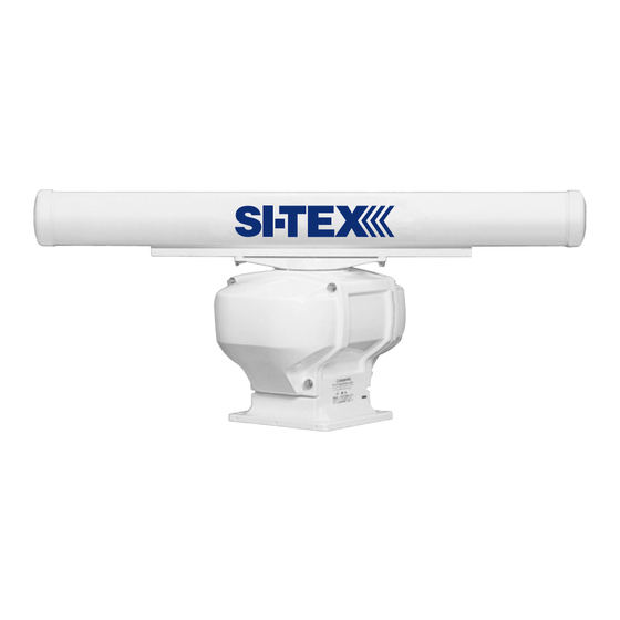
TABLE OF CONTENTS SAFETY PRECAUTIONS ......................5 High Voltage Warning ....................5 Microwave Radiation Hazard ..................5 Warning ......................5 Magnetron Preheating ....................6 1. INTRODUCTION ......................9 CONVENTIONS USED ..................9 INTRODUCTION ....................9 GENERAL INFORMATION ................9 Product Support Inquiries ................10 PACKING LIST .................... - Page 6 MDS-8 ...................... 25 3.1.0 Antenna Unit ..................25 3.1.1 Dimensions and Mounting ..............25 MDS-9 ...................... 26 3.2.0 Antenna Unit ..................26 3.2.1 Dimensions and Mounting ..............27 MDS-10-4/MDS-10-5 ..................28 3.3.0 Antenna Unit ..................28 3.3.1 Dimensions and Mounting ..............29 Appendix A.
-
Page 7: Introduction
If the Chart Plotter has a Radar selection, it has the software. If the Chart Plotter does not have the software, it is available by contacting Standard Horizon Marine Product Support at 800/767-2450 or your Standard Horizon dealer for a Software Card. See Par. 2.8 for software update procedure. -
Page 8: Product Support Inquiries
(in USA or Canada), Standard Horizon/Vertex Standard authorized dealers (Outside USA or Canada), or Si-Tex USA at (727) 576-5995. PACKING LIST When the package containing the Si-Tex Radar Antenna is first opened, please check for the following contents. Si-Tex Antenna (dome or open array) with 30Ft of routing cable Fasteners, stainless steel 4 Bolts, hex metric M8 x 25U (approx. -
Page 9: Installation
2. INSTALLATION This chapters illustrates the instructions on mechanical and electrical connections of the Radar and the necessary software settings to operate it. WARNING In order for the Radar Antenna to communicate with the Chart Plotter, the software must be configured as explained in the Par. -
Page 10: Installation Procedure
unit that are needed for installation or operation. The cable must remain attached. For ease of handling, coil the cable and place it on top of the scanner. Then secure it with tape. Invert the scanner and make sure the four mounting holes are clear to accept bolts. Working at higher elevations may become necessary while installing the scanner unit. -
Page 11: Connection Procedure
12-24VDC White Black JUNCTION BOX Black Orange Brown Yellow EXTERNAL SWITCH Blue Green Figure 2.3 - Antenna Cable CONNECTION PROCEDURE NOTE In the following procedure the small wires must be stripped and tinned, and then connected to the proper connections in the Radar Junction Box, and to pins on the On/Off control switch. If you are uncertain of your skill in completing these tasks, it is strongly advised to obtain the services of a qualified technician. -
Page 12: Radar Junction Box Connections
Figure 2.5 - Radar Junction Box Terminal Strip A - Chart Plotter This terminal strip is used to connect a compatible Standard Horizon GPS Chart Plotter to a Radar Antenna. Power – and Power+ connections are used to power the Standard Horizon Chart Plotter when connected. -
Page 13: Radar Antenna Connections
Standard Horizon Chart Plotter. Do not omit the in-line fuse unless a dedicated and fused terminal is available. If so, install a 5 Amp fuse. Terminal Strip C - Radar Cable This terminal strip is used to connect the Radar Antenna. -
Page 14: Chart Plotter Connections And Set Up
CHART PLOTTER CONNECTIONS AND SET UP The following instructions refer to Dome Antennas; refer to Open Array for connections. 2.7.0 CP180 & CP180i Connections A switch MUST be connected to turn the Radar On or Off Radar Switch PWR & ACC 1 Cable PLOTTER CABLE RADAR CABLE WIRE C L R FUNCTION... -
Page 15: Cp300 & Cp300I Connections
2. Move the ShuttlePoint knob to highlight ADVANCED SETUP and press [ENT]. 3. Move the ShuttlePoint knob to highlight IN/OUT CONNECTIONS and press [ENT]. 4. Move the ShuttlePoint knob to highlight PORT 1 INPUT and press [ENT]. 5. Move the ShuttlePoint knob up/down to select RADAR and press [ENT]. 6. -
Page 16: Cpv350 Connections
1. From the Chart page, press [MENU]. Move the ShuttlePoint knob to highlight SETUP MENU and press [ENT]. 2. Move the ShuttlePoint knob to highlight ADVANCED SETUP and press [ENT]. 3. Move the ShuttlePoint knob to highlight IN/OUT CONNECTIONS and press [ENT]. 4. -
Page 17: Port Setup
Port Setup When an optional Radar Antenna is connected, Port 1 of the NMEA In/Out Communication Setup menu must be changed to RADAR as shown below for communications. 1. From the Chart page, press [MENU]. Move the ShuttlePoint knob to highlight SETUP MENU and press [ENT]. -
Page 18: Port Setup
Port Setup When an optional Radar Antenna is connected, Port 1 of the NMEA In/Out Communication Setup menu must be changed to RADAR as shown below for communications. 1. From the Chart page, press [MENU]. Move the ShuttlePoint knob to highlight SETUP MENU and press [ENT]. -
Page 19: Port Setup
Port Setup When an optional Radar Antenna is connected, Port 1 of the NMEA In/Out Communication Setup menu must be changed to RADAR as shown below for communications. 1. From the Chart page, press [MENU]. Move the ShuttlePoint knob to highlight SETUP MENU and press [ENT]. - Page 20 Page 22 Radar Installation Manual...
-
Page 21: Technical Specifications
3. TECHNICAL SPECIFICATIONS Features MDS-1 MDS-8 MDS-9 MDS-10-4/MDS-10-5 Antenna 12.4 Inch-Dome 20 Inch-Dome 23.5 Inch-Dome 47.25/59.1 Inch-Open Array Peak Power Output Beam Width (degree) Horizontal 7° 4.7° 4.0° 2.4°/1.7 ° Beam Width (degree) Vertical 25° 25° 25° 25° Rotation (RPM) MDS-1 3.0.0 Antenna Unit... -
Page 22: Dimensions And Mounting
3.0.1 Dimensions and Mounting Figure 3.0.1 - Radar MDS-1 (I) Weight: 4.5 kg (10 lb) without cable Weight: 5.5 kg (12.5 lb) 10m cable included Figure 3.0.1a - Radar MDS-1 (II) Page 24 Radar Installation Manual... -
Page 23: Mds-8
MDS-8 3.1.0 Antenna Unit · Power supply : 10.8 to 41.6 VDC · Power consumption : 30W or less · Preheat times : 90 sec · Aerial : Radome 1.5 Feet · Peak power output : 2kW · Transmitting frequency : 9445+/-30MHz ·... -
Page 24: Mds-9
Weight: 8.1 kg (18.0 lb) 10m cable included Weight : 6.8 kg (15.0 lb) without cable Figure 3.1.1a - Radar MDS-8 (II) MDS-9 3.2.0 Antenna Unit · Power supply : 10.8 to 41.6 VDC · Power consumption : 45W or less ·... -
Page 25: Dimensions And Mounting
· Noise figure : 6.0dB or less · Operating Temperature : -25°C ~ +55°C · Operation in wind (relative) : 100 knots · Water Resistance : IPX6 (IEC60529) · Preheat times output (by 5 sec step) : 115 sec to 5 sec 3.2.1 Dimensions and Mounting Figure 3.2.1 - Radar MDS-9 (I) -
Page 26: Mds-10-4/Mds-10-5
MDS-10-4/MDS-10-5 3.3.0 Antenna Unit · Power supply : 10.8 to 41.6 VDC · Power consumption : 80W or less · Preheat times : 120 sec · Aerial MDS-10-4 or MDS-10-5 : Open 4 or 5 Feet · Peak power output : 4kW ·... -
Page 27: Dimensions And Mounting
3.3.1 Dimensions and Mounting Figure 3.3.1 - Radar MDS-10-4/MDS-10-5 (II) Weight: 21.2 Kg (47lb) 4 feet Weight: 21.9 Kg (49lb) 5 feet Figure 3.3.1a - Radar MDS-10-4/MDS-10-5 (III) Radar Installation Manual Page 29... - Page 28 Page 30 Radar Installation Manual...
-
Page 29: Appendix A. What Is Radar
Appendix A. WHAT IS RADAR? GENERAL The word “radar” is an acronym for “RAdio Detecting And Ranging.” In very simple terms, this is how it works. A radio transmitter sends a quick microwave pulse, and then a receiver listens for that signal’s echo when it is bounced back from something in its path. The returning signal is processed by a computer to determine its relative distance, position and bearing. -
Page 30: Characteristics Of Radar Wave
Beam Side lobe Main Side Antenna Figure A.0.1 - Antenna pattern CHARACTERISTICS OF RADAR WAVE Radio waves travel out from the antenna while bending slightly along the earth’s surface. The amount they bend depends on atmospheric conditions. The sight distance of a radar generally is about 6% longer than the optical sight distance and is calculated using this equation: Radar sight distance (NM) = 2.22 ( antenna height (m) + target height (m)) Line of sight... -
Page 31: False Echoes
create a shdow zone behind it and prevent you from seeing targets on the other side. More importantly, if a mast or some part of the boat’s superstructure is in the path of the antenna’s sweep, this will also create a shadow zone. No targets will be recognized behind it and it could create a dangerous situation. -
Page 32: False Echoes Caused By Side Lobe
Real echo Multiple echoes Figure A.1.2a - Multiple Echoes False echoes caused by side lobe An antenna’s side lobe emissions are low power, and will not register distant targets. However, if there is a strong reflecting target near your boat, it sometimes may appear as a circular-arc false echo on the screen. - Page 33 or eliminate the interference. Radar interference Figure A.1.2c - Radar interference Radar Installation Manual Page 35...
- Page 34 Page 36 Radar Installation Manual...
-
Page 35: Appendix B. Installation
Appendix B. INSTALLATION MORE INSTALLATION CONSIDERATIONS B.0.0 Shifting from keel line By shifting the scanner position from the keel line to the starboard side of the boat, it is possible to move shadow zones to the port side. This makes it possible to keep a clear view to the bow. -
Page 36: Installing Scanner Unit
INSTALLING SCANNER UNIT Use a mounting base such as the ones shown in Figure B.1, or you can install the scanner directly to a roof or other flat surface. Be certain you keep the water drain tube clear. It’s located at the bottom of the scanner unit. NOTE If the mounting bracket or surface has a curvature of more than 2mm, use spacers with the mounting bolts to prevent stress on the scanner housing. -
Page 37: Index
INDEX MDS-9 ............. 26 Microwave Radiation ......... 5 Aerial ........... 23, 25, 26, 28 Mounting ........24, 25, 27, 29 Antenna ............31 Multiple echoes ..........33 ANTENNA CONNECTIONS ......15 Antenna Unit ....... 23, 25, 26, 28 Noise figure ......... 23, 25, 27, 28 Backing up ............ - Page 38 STANDARD HORIZON cannot be responsible in any way for ancillary equipment not furnished by STANDARD HORIZON which is attached to or used in connection with Products, or for the operation of the Product with any ancillary equipment, and all such equipment is expressly excluded from this warranty.
Need help?
Do you have a question about the SI-TEX RADAR and is the answer not in the manual?
Questions and answers