Table of Contents
Advertisement
Standard Handles
EQUIPMENT
. . . . . . . . . . .
SELECTION
Model 425--16 Cutter
Standard Handles
Pistol Grip and "D" Handles 4025075
without heat exchanger
Balancer
. . . . . . . . . . . . . . . . . . . .
JARVIS
6225030::.
Ordering No.
. . . . . . . .
4025072
. . . .
4027266
. . . . . .
4027307
4042045
®
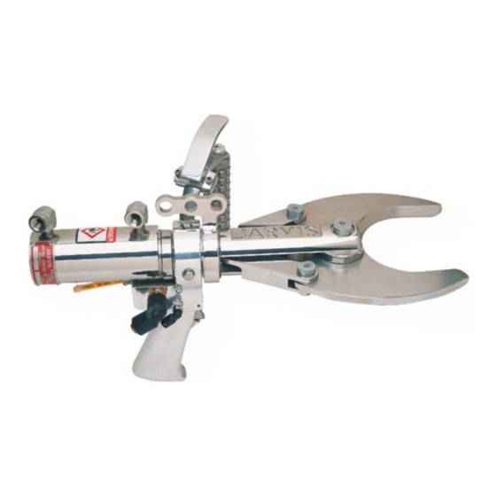
Model 425- -16
Hydraulic Cutter
Pistol Grip and "D" Handle
TABLE OF
CONTENTS
. . . . . . . . . . . . . . . . . . . . . . . . . . . .
• Safety Messages to Employer and Safety
Director
. . . . . . . . . . . . . . . . . . . . . . . . . . . . . . . . .
• Safety Messages to Operators, Maintenance
and Cleanup Personnel
. . . . . . . . . . . . . . . . . . . . . . . . . . .
TEL. 860-347-7271
FAX. 860-347-6978
. . . . . . . . . . . . . . . . . . .
. . . . . . . . . . . . . . . . . . . .
. . . . . . . . . . . . . . . . . . . . .
. . . . . . . . . . . . . . . . . . .
. . . . . . . . . . . . . . . . . . . .
. . . . . . . . . . . . . . . . .
jarvis.products.corp@snet.net
jarvisproducts.com
WWW.
Page
2
3
4
11
12
12
14
14
Advertisement
Table of Contents

Related Manuals for Jarvis 425-16

Summary of Contents for Jarvis 425-16
-
Page 1: Table Of Contents
....4042045 • Maintenance Instructions ....JARVIS PRODUCTS CORPORATION ® 33 ANDERSON ROAD, MIDDLETOWN, CONNECTICUT 06457-4926 jarvis.products.corp@snet.net... - Page 2 8. Avoid injury. Do not permit the tool to be misused. 9. If you resell or distribute a Jarvis product, you must provide the purchaser with the appropriate safety sheets and tool brochure. Additional copies of safety sheets and tool brochures will be provided upon request.
- Page 3 8. Never depress the triggers unless you want to use or test the tool. 9. Never make modifications or alterations to the tool. Report or replace any missing or illegible labels. JARVIS PRODUCTS CORPORATION ®...
- Page 4 Model 425--16 page 4 of 16 Figure A G Jarvis service tool 8039092 is available for locking ring removal and installation. ITEM PART NO. PART NAME 1014092 Compression Spring 1051118 Male Elbow Fitting 1051083 Male Elbow Fitting...
-
Page 5: Jarvis.products.corp@Snet.net
Link Pin 3019209 Rear Handle Assembly 1007023 Hex Lock Nut (includes items 1--11, 14, 1011319 Yoke 34 and 35) JARVIS PRODUCTS CORPORATION ® 33 ANDERSON ROAD, MIDDLETOWN, CONNECTICUT 06457-4926 jarvis.products.corp@snet.net UNITED STATES OF AMERICA E- -MAIL. jarvisproducts.com TEL. 860-347-7271 FAX. 860-347-6978 WWW. -
Page 6: Jarvis.products.corp@Snet.net
Quantity for 425--16 model 4025072 is two (2). Quantity for 425--16 model 4025075 is one (1). Quantity for 425--16 model 4025072 is three (3). Quantity for 425--16 model 4025075 is two (2). JARVIS PRODUCTS CORPORATION ® 33 ANDERSON ROAD, MIDDLETOWN, CONNECTICUT 06457-4926 jarvis.products.corp@snet.net... -
Page 7: Hydraulic Power Unit
Filter Element only 1011087 Quick Connect Socket 1034052* Square Filter Assy w/Element 1017085 Electrical Danger Label 1034048* Filter Element only for Sq. Filter JARVIS PRODUCTS CORPORATION ® 33 ANDERSON ROAD, MIDDLETOWN, CONNECTICUT 06457-4926 jarvis.products.corp@snet.net UNITED STATES OF AMERICA E- -MAIL. jarvisproducts.com TEL. -
Page 8: Jarvis.products.corp@Snet.net
Coil for 115v Valve 1034013 Oil Breather Filler Cap 1063844 din/iso Coil for 220v Valve 1017085 Electrical Danger Label JARVIS PRODUCTS CORPORATION ® 33 ANDERSON ROAD, MIDDLETOWN, CONNECTICUT 06457-4926 jarvis.products.corp@snet.net UNITED STATES OF AMERICA E- -MAIL. jarvisproducts.com TEL. 860-347-7271 FAX. -
Page 9: Parts Diagram And List
Flange, Suction Line 1034048* Filter Element only 1034013 Oil Breather Filler Cap 1061739 Heat Exchanger 1017085 Electrical Danger Label JARVIS PRODUCTS CORPORATION ® 33 ANDERSON ROAD, MIDDLETOWN, CONNECTICUT 06457-4926 jarvis.products.corp@snet.net UNITED STATES OF AMERICA E- -MAIL. jarvisproducts.com TEL. 860-347-7271 FAX. 860-347-6978 WWW. -
Page 10: Jarvis.products.corp@Snet.net
Electrical Warning Label, 220v 1050027 Street Elbow 3016193 Control Box Complete, 115v 1050016 Hex Nipple 3016212 Control Box Complete, 230v JARVIS PRODUCTS CORPORATION ® 33 ANDERSON ROAD, MIDDLETOWN, CONNECTICUT 06457-4926 jarvis.products.corp@snet.net UNITED STATES OF AMERICA E- -MAIL. jarvisproducts.com TEL. 860-347-7271 FAX. 860-347-6978 WWW. -
Page 11: Installation Diagram
Yellow Hose Hydraulic Hydraulic Return Hose Pressure Hose Connection Connection Hydraulic Return Hose Hydraulic Pressure Hose JARVIS PRODUCTS CORPORATION ® 33 ANDERSON ROAD, MIDDLETOWN, CONNECTICUT 06457-4926 jarvis.products.corp@snet.net UNITED STATES OF AMERICA E- -MAIL. jarvisproducts.com TEL. 860-347-7271 FAX. 860-347-6978 WWW. 6225030::. -
Page 12: Specifications
Older boards use a square 1 Install the 425- -16 above the work station from a potentiometer with a screw driver slot. balancer. Jarvis part number 4042045 is available. Newer boards use a group of four rocker switches. 1.1 The 425- -16 should have sufficient travel to allow the operator to reach the entire work area. -
Page 13: Jarvis.products.corp@Snet.net
L4 = ATD circuit 2 on Control L5 = ATD circuit 1 on Valve L6 = Power on terminals 2 and 3 Electric/Pneumatic Control Box JARVIS PRODUCTS CORPORATION ® 33 ANDERSON ROAD, MIDDLETOWN, CONNECTICUT 06457-4926 jarvis.products.corp@snet.net UNITED STATES OF AMERICA E- -MAIL. -
Page 14: Operation Instructions
PROCEDURES (29 CFR 1910.147) WHEN INSTALLING as necessary. OR REMOVING A BLADE. ALWAYS DISCONNECT ALL HYDRAULIC AND AIR HOSES AND SHUT THEPOWER 1.5 Apply Jarvis 1315 White Grease to the top holes ACCORDANCE WITH OSHA’S in blade and link pins (items 42 and 46). -
Page 15: Hex Head Screw
1.7 Check that the blades are opening and closing smoothly and that they are meshing properly. If 4.2 Apply light coat of Jarvis 1315 White Grease to the blades do not have a smooth sliding contact sliding surface of each blade (item 44) prior to during cutting, the main pivot blade pin (item insertion into clevis housing (item 51). -
Page 16: O--Ring
5. See notes below. (item 26). 7.8 Remove o- -ring (item 21) from cylinder (item 6.1.1 Apply Jarvis 1315 White Grease to dowel 18). pin (item 49) and sliding surfaces of links 7.9 Clean and inspect all parts for wear and replace (item 45) before inserting into clevis as necessary.
Need help?
Do you have a question about the 425-16 and is the answer not in the manual?
Questions and answers