
Summary of Contents for Pyronix V2 GSM
- Page 1 GSM Speech Dialler with Automation Control Microphone Speaker PROGRAMMING AND INSTALLATION MANUAL RINS1323-8...
-
Page 2: Press The T Key And Enter The
EASY START GUIDE Enter 2 0 1 Press the t key and enter the inputs for input 1. Repeat for other inputs if required [201-209] Enter 999 Press the t key to exit the engineers mode. Enter 1 2 3 4 This enters the user menu. -
Page 3: Table Of Contents
4.1 S ..................7 CROLLING HROUGH ENUS 4.2 E ......................8 NTERING CHAPTER 5: V2 GSM PROGRAMMING ............. 10 5.1 P VOICE M [100] ............. 10 ECORD YSTEM ESSAGES 5.1.1 Play / Record Low Battery Message [101] ............10 5.1.2 Play / Record Battery Restore Message [102] ........... 10 5.1.3 Play / Record Test Message [103] .............. - Page 4 UTPUT XPANDER 7.9 T ......................42 NTENNA 7.10 C ................43 ONNECTING OTHER EQUIPMENT CHAPTER 8: DISCLAIMER .................. 44 CHAPTER 9: SETTING UP THE V2 GSM (EXAMPLE) ........45 CHAPTER 10: SHORTCUT FUNCTION REFERENCE ........47 Pyronix Ltd Page: 4...
-
Page 5: Chapter 2: Introduction
Up to 9 telephone numbers can be programmed, and either a voice message or SMS text maybe sent after activation. The V2 GSM also has a user menu that can be accessed by dialling the V2 GSM directly (this is a mobile number that is supplied). -
Page 6: Chapter 3: Powering Up / Engineers Menu
C H A P T E R 3 : P O W E R I N G U P / E N G I N E E R S M E N U When the V2 GSM is powered up for the first time (after a SIM card has been installed) a message will be displayed stating it is the ‘first time power up defaults’. -
Page 7: Chapter 4: Operating The Keypad
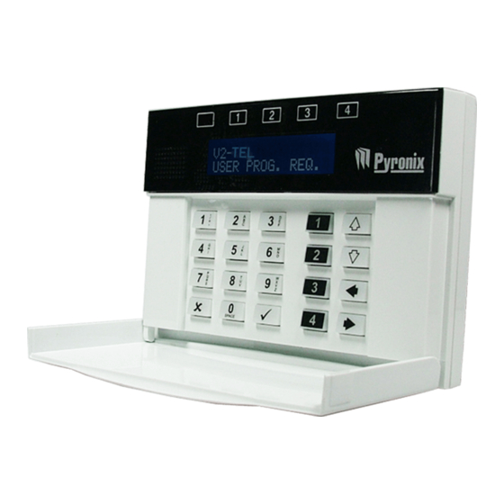
C H A P T E R 4 : O P E R A T I N G T H E K E Y P A D The V2 GSM keypad incorporates 4 status LEDs positioned above the LCD display. They are numbered 1 to 4 and are used to show the status of the 4 on board outputs. -
Page 8: Entering Text
4 . 2 E N T E R I N G T E X T The numeric keys above are used to enter the text onto the V2 GSM (for SMS texts). For example to enter the letter ‘Q’. The 7 key needs to be entered twice. The 0 key is used to enter a space. - Page 9 V2 GSM Installation Manual Scrolls between sub-menu items Moves the character cursor to the end of a string Scrolls between sub-menu items Moves the character cursor to the beginning of a string Scrolls between main-menu items Moves the character cursor to...
-
Page 10: Chapter 5: V2 Gsm Programming
5 . 1 P L A Y / R E C O R D S Y S T E M V O I C E M E S S A G E S [ 1 0 0 ] Voice or SMS messages can be recorded for all system messages on the V2 GSM: Low battery message = If the GSM voltage supply equipment battery drops below 11.5V... -
Page 11: Play / Record Jamming Message [104]
4 - RECORD To record a message, press 4. After 3 seconds, the message can be recorded (the microphone is situated near the Pyronix logo). The message recording can be 12 seconds long or press x to stop the recording at anytime. -
Page 12: Write Sms System Messages [130]
5 . 2 W R I T E S M S S Y S T E M M E S S A G E S [ 1 3 0 ] SMS Messages can be recorded for all system messages on the V2 GSM: Low battery message = If the GSM voltage supply equipment battery drops below 11.5V... -
Page 13: Sms Jamming Message [134]
V2 GSM Installation Manual 5.2.4 SMS jamming message [134] Press the t key to enter a SMS jamming message See Section 5.2.6 On how to enter SMS messages 5.2.5 SMS battery restore message [135] Press the t key to enter a SMS jamming restore message See Section 5.2.6 On how to enter... -
Page 14: Call Redials [150]
5 . 3 C A L L R E D I A L S [ 1 5 0 ] If the V2 GSM calls the user and the call is not answered, the V2 GSM can be programmed to redial each telephone number 9 times. -
Page 15: Immediate Number Of Redials [165]
V2 GSM Installation Manual 5 . 5 I M M E D I A T E N U M B E R O F R E D I A L S [ 1 6 5 ] This function enables the splitting of the number of calls made to the user if the users phone does not answer. -
Page 16: Default Call Timeout [171]
5 . 8 C A L L I N G S T R A T E G Y [ 1 7 2 ] SEQUENTIAL = The V2 GSM will dial in sequence all numbers programmed for as many times as number of redials have been programmed for this number. -
Page 17: Voice Message Repeats [174]
V2 GSM Installation Manual 5 . 1 0 V O I C E M E S S A G E R E P E A T S [ 1 7 4 ] Voice messages can be repeated up to 9 times during a call if required. -
Page 18: Rings
5 . 1 3 R I N G S B E F O R E A N S W E R [ 1 7 7 ] The remote menu of the V2 GSM is accessed when the telephone number of the V2 GSM is dialled. -
Page 19: Number
5 . 1 5 T E L E P H O N E N U M B E R I N P U T A L L O C A T I O N [ 2 0 0 ] This function is used to allocate the inputs for each telephone number, so when an input (or inputs) on the V2 GSM system activates, it will dial the programmed telephone number. -
Page 20: Enable Clip For Tel # [300]
5 . 1 7 E N A B L E C L I P F O R T E L # [ 3 0 0 ] CLIP is used in conjunction with the output type ‘CLIP Pulse’ (function 660) to activate remotely outputs without having to wait for the V2 GSM to take the phone line. For example: If telephone number#1 is enabled for CLIP. -
Page 21: Program Input Status [400]
5 . 1 9 P R O G R A M I N P U T S T A T U S [ 4 0 0 ] Each of the 6 inputs onboard the V2 GSM can be programmed to be either normally open, normally high, normally low or a voltage trigger. -
Page 22: Input 1-6 Response Time [450]
5 . 2 1 I N P U T 1 - 6 T R I G G E R V O L T A G E [ 5 0 0 ] This function sets the trigger voltage for each individual input (the V2 GSM onboard inputs only, function not available for the RIX inputs). -
Page 23: Nput 1-6 Restore Voltage [530]
5 . 2 2 I N P U T 1 - 6 R E S T O R E V O L T A G E [ 5 3 0 ] This function sets the restore voltage for each individual input (the V2 GSM onboard inputs only, function not available the RIX inputs). -
Page 24: Enable Abort Input #6 [580]
5 . 2 4 E N A B L E A B O R T I N P U T # 6 [ 5 8 0 ] This function enables the abort option which can be used on Input 6 of the V2 GSM. If this input is activated, all dialling sequences will be aborted. -
Page 25: Set Sim -Card Secret Pin [601]
5 . 2 8 T E S T R E M O T E M I C R O P H O N E [ 6 0 2 ] This tests the remote microphone if one is connected to the V2 GSM. -
Page 26: View Event Log [604]
5 . 3 0 V I E W E V E N T L O G [ 6 0 4 ] All events that occur are recorded in the event log. The V2 GSM display will show all information in order, starting at the most recent event. The above display shows the following:... -
Page 27: Reset To Factory Defaults [607]
The V2 GSMs will then need to be assigned ‘Master’ and ‘Slave’. The jamming feature works by the V2 GSM ‘Slave’ calling the Master after a programmed time (see 5.37 jamming time window). If the Master receives the call successfully, operation is continued as normal. -
Page 28: Jam Detect Partner Number [610]
5 . 3 6 J A M D E T E C T P A R T N E R N U M B E R [ 6 1 0 ] This is the telephone number of the 2 V2 GSM on site. Press the [ or ] keys to scroll to ‘JAM DETECT PARTNER NUMBER’... -
Page 29: Enable Expander Output Modules
5 . 3 9 E N A B L E E X P A N D E R O U T P U T M O D U L E S [ 6 5 0 ] Up to 3 output modules (ROX, 16 relay outputs) can be installed on the V2 GSM. Each ROX that is connected need to be enabled in this function. -
Page 30: Pgm 1-4 Output Functions [660]
V2 GSM Installation Manual Press the [ or ] keys to scroll to ‘PGM 1-4 OUTPUT FUNCTIONS’ or enter ‘660’. Press B or T to select the output number enter the function shortcut number (see below).. Press t Press B or T to choose between... -
Page 31: Pgm 1-4 Output Timers [680]
5 . 4 1 P G M 1 - 4 O U T P U T T I M E R S [ 6 8 0 ] This function is used in conjunction with function 660 and any outputs that are programmed as either ‘follow input’ or a pulsed output (the V2 GSM onboard outputs only, function not available the ROX inputs). -
Page 32: Output Control [700]
5 . 4 2 O U T P U T C O N T R O L [ 7 0 0 ] This function is used to activate any output on the V2 GSM, whether that is the 4 on board, or any of the remote outputs on the expanders. -
Page 33: Chapter 6: User Menu Prompts
The V2 GSM is pre-programmed with default prompts for the user menu (this is when a user will receive a phone call from the V2 GSM or dials in directly to the V2 GSM – if ‘remote control’ is enabled). Each prompt can be changed by a ‘hidden’ menu that is only... -
Page 34: Play/Record Voice Prompt: 3 [113]
V2 GSM Installation Manual 6.1.3 Play/Record Voice Prompt: 3 [113] “Press one to listen, Two to talk and listen, Three to control output, Four for system status, or press Zero to hang up” To change the above message, enter ‘113’... -
Page 35: Play/Record Voice Prompt: 6 [116]
V2 GSM Installation Manual 6.1.6 Play/Record Voice Prompt: 6 [116] “Output on” To change the above message, enter ‘116’ Press t 1 = To play a message 4 = To record 9 = To delete The message can only be 5 seconds 6.1.7 Play/Record Voice Prompt: 7 [117]... -
Page 36: Play/Record Voice Prompt: 9 [119]
V2 GSM Installation Manual 6.1.9 Play/Record Voice Prompt: 9 [119] “Enter your call acknowledgement code now” To change the above message, enter ‘119’ press t 1 = To play a message 4 = To record 9 = To delete The message can only be 5 seconds 6.1.10 Play/Record Voice Prompt: 9 [120]... -
Page 37: Chapter 7: Installation Section
V2 GSM Installation Manual C H A P T E R 7 : I N S T A L L A T I O N S E C T I O N 7 . 1 T H E V 2 G S M P R I N T E D C I R C U I T B O A R D... -
Page 38: Technical Specification
V2 GSM (as shown below). (Bottom of V2 GSM) Lever the screwdriver and push the lugs inwards and pull the back of the V2 GSM away from the front. 7 . 4 S C R E W M O U N T I N G H O L E S... -
Page 39: Installing Asim- Card
7 . 5 I N S T A L L I N G A S I M - C A R D Before the V2 GSM is operational, a SIM card needs to be present. This can either be a pay as you talk SIM card, or a pay monthly one. -
Page 40: Connecting An Input Expander (Pc X -Rix8)
7 . 7 C O N N E C T I N G A N I N P U T E X P A N D E R ( P C X - R I X 8 ) Only 1 input expander can be connected to the V2 GSM, this will need to be addressed as ‘0’... -
Page 41: Connecting An Output Expander (Pcx-Rox16R)
7 . 8 C O N N E C T I N G A N O U T P U T E X P A N D E R ( P C X - R O X 1 6 R ) Up to 3 output expanders may be installed on the V2 GSM. Each output expander must... -
Page 42: The Antenna
V2 GSM Installation Manual 7 . 9 T H E A N T E N N A The antenna cable must be guided through the clip present at the top right of the V2 printed circuit board (as shown) The cable should then be guided through the top hole on the back of the V2 as shown below. -
Page 43: Onnecting Other Equipment
V2 GSM Installation Manual 7 . 1 0 C O N N E C T I N G O T H E R E Q U I P M E N T Connecting Inputs Connecting Smoke / PA Buttons Connecting Relays... -
Page 44: Chapter 8: Disclaimer
C H A P T E R 8 : D I S C L A I M E R If there are 2 V2 GSM units on the property, if enabled, jamming test calls will send regular test calls at programmed intervals. If these test calls are successful, no charge is made. However, if the test call is unsuccessful a charge will occur (this may be costly depending on how regular the test calls have been programmed and how many times the call is made before the problem is fixed). -
Page 45: Chapter 9: Setting Up The V2 Gsm (Example)
V2 GSM Installation Manual C H A P T E R 9 : S E T T I N G U P T H E V 2 G S M ( E X A M P L E ) If possible it would be ideal to have the V2 already installed before programming to check the quiescent state of the Inputs to be used. - Page 46 Press the x key to return to the Main menu enter code 999 quit/exit programming press the t key. The date and time should appear after a short while and the signal strength bars should be visible. The V2 GSM is ready for use. Pyronix Ltd Page: 46...
-
Page 47: Chapter 10: Shortcut Function Reference
V2 GSM Installation Manual C H A P T E R 1 0 : S H O R T C U T F U N C T I O N R E F E R E N C E PLAY / REC SYSTEM VOICE MESSAGES... - Page 48 V2 GSM Installation Manual INPUTS 1-6 DIAGNOSTICS 551-536 Diagnostic for input#1 [551], Diagnostic for input#2 [552] … Diagnostic for input#6 [556] ENABLE ABORT INPUT#6 ENABLE STATUS INPUT#5 CALL TELEPHONE NUMBER SET SIM-CARD SECRET PIN TEST REMOTE MIC TEST REMOTE SPEAKER...
-
Page 49: Pyronix Ltd Page
V2 GSM Installation Manual Pyronix Ltd Page: 49... - Page 50 V2 GSM Installation Manual Pyronix Ltd Page: 50...
- Page 51 V2 GSM Installation Manual Pyronix Ltd Page: 51...
- Page 52 Secure Holdings Pyronix House Braithwell Way Hellaby Rotherham S66 8QY Customer Support line (UK only): +44(0)845 6434 999 (local rate) Or telephone: +44(0)1709 535225 Hours of business: 8:00 AM – 6:30 PM, Monday to Friday Email: customer.support@pyronix.com Website: www.pyronix.com...
Need help?
Do you have a question about the V2 GSM and is the answer not in the manual?
Questions and answers