
Related Manuals for Ateis DIVA8M

Summary of Contents for Ateis DIVA8M
-
Page 1: User Manual
DIVA8M User Manual Version 1.1 Ateïs International Ch. du Dévent, 1024 Ecublens, Switzerland. Phone : +41 21 881 25 10... -
Page 2: Table Of Contents
1.4.4 System Configuration ........................7 1.4.5 System Control ..........................7 ......................... 7 AFETY ECLARATION HARDWARE DESCRIPTION ........................ 10 DIVA8M F ........................11 RONT VIEW DIVA8M R ......................... 12 EAR VIEW DIVA8S F ........................13 RONT VIEW DIVA8S R .......................... 14... - Page 3 ..........................30 7.2.1 File ..............................30 7.2.2 Edit ..............................31 7.2.3 View ............................... 31 7.2.4 User ............................... 33 7.2.5 Operation ............................33 7.2.6 Tools .............................. 34 7.2.7 Lock ............................... 34 7.2.8 Window ............................35 7.2.9 Help ............................... 35 ............................36 OOLBARS .............................
- Page 4 8.23.2 From Logic Input ........................103 8.23.3 From Software ........................105 8.24 ..........................106 OGIC NPUTS 8.24.1 Normal Logic Inputs ....................... 107 8.24.2 Evacuation Inputs ........................108 8.24.3 External Fault Inputs ......................109 8.25 ..........................110 ONITORING 8.25.1 Zone Monitoring ........................
-
Page 5: Welcome
1 Welcome Thank you for choosing ATEÏS DIVA8M . We (at ATEÏS) hope you will enjoy to use this exciting piece of technology as much as we enjoy developing and building it. This Help file version is: Ver.EN.1.1 This files has been written for the ATEIS DIVA software version: VER1.0.1.19 This manual can be updated at any time without prior notice in order to keep this manual up to date. -
Page 6: Contact
Phone: +41 (0)21/ 881 25 10 Fax: +41 (0)21/ 881 25 09 Mail: info@ateis-international.com http://www.ateis-international.com 1.3 Installation DIVA8M Package Content: Opening the box you should find the following items: • DIVA Master Unit • Rack rounting brackets, 2 pcs •... -
Page 7: System Overview
This paragraph intend to briefly described the main DIVA properties. 1.4.1 General The DIVA8M module unit houses: audio digital processing (DSP), a matrix, a digital message player, a fully monitored fireman microphone, amplifiers monitoring with switchover to backup amplifier and loudspeaker lines monitoring. - Page 8 • Do not expose the DIVA to extreme temperatures, direct sunlight, humidity, or dust, which could cause fire or electrical shock hazard. • Keep away water or other liquids from the DIVA. Otherwise fire or electrical shock may result. • Connect the power cord only to an AC outlet of the type stated in this Owner's Manual or as marked on the unit.
- Page 9 • Do not use benzene, thinner, or chemicals to clean the DIVA. Use only a soft, dry cloth. • If the DIVA is moved from a cold place (e.g., overnight in a car) to a warmer environment, condensation may form inside the unit, which may affect performance. Allow the DIVA to acclimatize for about one hour before use.
-
Page 10: Hardware Description
2 Hardware Description DIVA's conception lead to a very intuitive front panel as well as very complete connection solutions on the back panel. In the next four paragraph, the DIVA8M/S front panel and the rear panel connection board are detailed. -
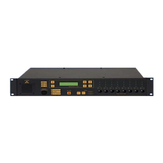
Page 11: Diva8M Front View
2.1 DIVA8M Front view Ateïs International Ch. du Dévent, 1024 Ecublens, Switzerland. Phone : +41 21 881 25 10... -
Page 12: Diva8M Rear View
2.2 DIVA8M Rear view Ateïs International Ch. du Dévent, 1024 Ecublens, Switzerland. Phone : +41 21 881 25 10... -
Page 13: Diva8S Front View
2.3 DIVA8S Front view Zone Event Indicator LEDs Power Indicator Zone Selection Buttons Ateïs International Ch. du Dévent, 1024 Ecublens, Switzerland. Phone : +41 21 881 25 10... -
Page 14: Diva8S Rear View
2.4 DIVA8S Rear view Ateïs International Ch. du Dévent, 1024 Ecublens, Switzerland. Phone : +41 21 881 25 10... -
Page 15: Software
3 Software As briefly mentioned in the Installation paragraph, DIVA8M package hold a CD-Rom. The CD contain the DIVA8M Quick Start Manual (.pdf), User Manual (Microsoft® HTML Help Executable .chm, HTML .htm). and DIVA software. It could happen that the software on the CD-Rom is not the last release. In that case, please visit ATEÏS website... - Page 16 Choose an installation folder, by default, it will be install in C:\Program Files Then launch the installation process by clicking "Install". Ateïs International Ch. du Dévent, 1024 Ecublens, Switzerland. Phone : +41 21 881 25 10...
- Page 17 To finish the Installation process, just click "Finish". The installation process will automatically create a Desktop Icon like the one under. Ateïs International Ch. du Dévent, 1024 Ecublens, Switzerland. Phone : +41 21 881 25 10...
-
Page 18: Uninstall
To uninstall a current version of the DIVA software, please follow the next few steps: Click on "start" -> "Program" -> ATEIS -> DIVA -> ATEIS DIVA v1.0.0-Uninstall Windows Installer will ask you if you are really sure to remove this program, click "Yes". -
Page 19: External Devices
4 External Devices This chapter will quickly describe the external devices that could be connected to a DIVA unit. It won't speak about external contact or button that also could be used. For more information about those devices, please visit ATEÏS website. -
Page 20: Psm
The PSM8 is a 10 keys call station of which 8 are programmable with microphone, integrated loudspeaker and buzzer. It can be used with either IDA4(X)(M)(s) or DIVA8M. it is possible to add up to 11 extensions to the PSM8 increasing programmable keys number to 96. - Page 21 • 2 internal screw connectors for 0 dB audio: • audio output from PPM microphone --> Audio Output (connect to the Audio In of the LAP) • audio input to PPM speaker --> Audio Input (connect to the Audio Output of the LAP, if needed) •...
-
Page 22: Diva Philosophy
5 DIVA Philosophy Before going any further, the philosophy of DIVA have to be exposed. This chapter will be split in three parts: • Front Panel • Software • Events 5.1 Front Panel The DIVA front panel have been made for basic controls operation as well as to define basic settings. Some features of the front can be disabled in case of advanced configuration. -
Page 23: Front Panel Operations
6 Front Panel Operations This chapter will describe all the operations that can be achieved from the front panel. In order to be clear as possible, this chapter will be divider by theme: • Menu • Music • Messages Some operation from the front panel required an higher level than level 1, in that case you will have to enter a valid user name and password. -
Page 24: Mac Number
• Enter your user name • Enter your password • You will be log in a your user account • Press ESC to go out of the menu 6.1.3 Mac Number In the world of computer networking, there is one common way to set an quasi-unique identifier to a network device. -
Page 25: Set Time
• Press ESC to go out of the menu 6.1.5 Set time On DIVA front panel, you can set the current location time format as well as the current date and time. • Use arrow keys to access the set time menu •... -
Page 26: Stop All Events
6.1.9 Stop All Events From the front panel of DIVA, you are able to stop all the running events (events are discussed in to use events). • Use arrow keys to access the STOP ALL EVENTS menu • Press OK, it will ask you "Are you sure to Stop all events?" •... -
Page 27: Music
• Use the arrow keys to access the Get Reference menu • Press OK • Choose between zone 1 - 8 or Music Amplifier - Voice Amplifier • Press OK The new monitoring reference is now made and stored. 6.2 Music On DIVA front panel, you have the possibility to assigned music sources to a zone (or multiple), set up attenuation for each speaker zone and to toggle between music sources. -
Page 28: Fireman Microphone
6.3.2 Fireman Microphone Next steps are for zone call with the fireman microphone: • Press the zone button(s) where you want the call to be played. The corresponding green selection LED(s) should light(s) up • Press the fireman microphone contact to start speaking in the selected zone(s), the corresponding EVAC LED(s) should light(s) up Note: If the fireman microphone paging event has pre-defined zones, pressing the microphone button will start a call in the pre-defined zone. -
Page 29: Diva Software Presentation
• Either by double-clicking on the Desktop icon: • Or by start -> program files -> Ateis -> ATEIS DIVA v1.x.x. The DIVA software starts with no file loaded and a blank worksheet looking as follow: Startup View Elements: Displays the path name of the active file. -
Page 30: Title Bar
Shows the window title of all open design and component Tab Bar control windows for quick access. Holds all design component libraries. Design Component Section This area is your work space showing all design windows and Design View Area component control windows. This section slides up for 'System Status', 'LED Display'. -
Page 31: Edit
• New: Opens a new system file • Save: Saves the current system file • Save as: Opens the 'Save As...' dialog window to choose file path and name • Open: Opens the 'Open...' dialog window to choose an existing file path and name •... - Page 32 • System: Calls the 'System' library control window to add and create a network system • Preset List: Calls the 'Component' library control window to choose DSP components • LED Display: Calls the 'System Status' control window • System Status: Calls the 'PPM Chime' control window for assigning pre- and post-announcement chimes ________________ •...
-
Page 33: User
• Toolbars: Within this menu subgroup you'll find the commands to call closed or hidden toolbars or floating toolbox items > Edit > Compile > Preset > Control > Function Link > Help > Windows Manager 7.2.4 User Here you are able to manage the user right: add users with a password and restrict access only to needed features. -
Page 34: Tools
• Set Date/Time: Allow user to set the time and date of the DIVA unit • Set Store Password: Offers a store process protection, password management • Compile: Compiles the current configuration and displays eventual errors • Store: Upload configuration parameter into the DIVA's parameter memory •... -
Page 35: Window
• Lock: Locks the software. Note: if no password were specified, every user can unlock the software • Set Password: Offers the possibility to set a password for unlocking the software. If set, as soon as you press the unlock button, it will prompt you to enter the last password set 7.2.8 Window This menu provides window arrangement commands, and quick access to open design or component control windows... -
Page 36: Toolbars
• About: Opens a information windows about copyrights, software release version, etc. • User Manual: Opens the complete help user manual 7.3 Toolbars In the DIVA software, the different toolbars offers shortcut to main menu items. Here are the list of them from left to right and up to down: •... -
Page 37: Tab Bar
• Store: Upload configuration parameter into the DIVA's parameter memory • Reverse: Downloads the DIVA configuration in the computer _________________________________________________________________________________ • Connect: Establishes data connection to the machine(s) in order to monitor or adjust parameters online • Disconnect: Disconnects DIVA software from the machine(s) •... - Page 38 • DIVA System: In the DIVA System folder, you will find DIVA Master unit icon. See How to Add Design Component • Audio source: In Audio Source folder, you will find audio elements that can be connected to a master DIVA unit. >Fireman Microphone: see How to use a Fireman Microphone >PSS: see...
-
Page 39: Design View Area
7.6 Design View Area In this area, you will: • Develop your DIVA configuration (see the How To chapter) and DIVA master network (see How to perform a DIVA master Network) • Access the monitor window, see How to Use Monitoring •... -
Page 40: Status Bar
• LED Display: offers real time status LED display, only if connected to DIVA units. It is a replic of the front panel LED display 7.8 Status Bar The status bar shows quick look status information about: • Connection: Lights up when connected to DIVA •... -
Page 41: How To
8 How To? The How To section is divided by theme. Each Theme discusses about how to perform an action or multiple action in order to build a configuration. The Philosophy of this chapter is that if you read it from A to Z, you will be able to perform a full advanced DIVA configuration. -
Page 42: Open
Here you will find procedures to: • Open a file • Save a file • Save a file as • Set an Autosave process 8.1.1 Open Open a DIVA file: Click on the Open Icon (Highlighted in picture below) in the Edit toolbar or go to menu File -> Open or even press ctr+o. -
Page 43: Print Project
• Tick the "Autosave your design" option in order to activate the autosave option • Choose after how much time the "autosave" will automatically run. • Choose how many recent files would be visible in the menu file -> recent 8.2 Print Project In order to print a project, you need to access the print preview page. -
Page 44: Start A New Project
The print toolbar include: • Print Button: in order to send the print request • Print Setting Button: in order to set your printer parameters • Master Drop-Down Menu: here you can change the DIVA master unit • Items Drop-Down Menu: Here you can select which window have to be print, choose between 'System configuration', 'Master Configuration' and 'DSP Configuration' 8.3 Start a New Project In order to start a new project, go to the menu: File ->... - Page 45 Once the new project is started, you will need to set up the network otpion as well as the correct IP adress, see How To Configure Network Option How To Set IP Address. By double-clicking the DIVA icon, you will enter the master window page, see below. In the Master window you will be able to add design components set settings for the integrated...
-
Page 46: Change Color Scheme
8.4 Change Color Scheme In the Color Scheme Options page, you will be able to personalize the colour scheme of DIVA software. You can change colour for: • Background • Label • DSP element • Other (Windows and Buttons) By using the "Use Default" button, you can retrieve default color scheme. 8.5 Configure Network Options In order to be able to communicate with DIVA master units, you have to set your network parameters. -
Page 47: Use The User Management
After all the network options have been set, please refer to the How To Set IP Address paragraph. 8.6 Use the User Management To access the user management window, go on the menu User -> User Management. Ateïs International Ch. du Dévent, 1024 Ecublens, Switzerland. Phone : +41 21 881 25 10... -
Page 48: Add User Account
The picture above shows the main page of the user manager. In this page you will be able to add new user account, delete account and modify account settings. The list below explains how the button works: • Add: allows to add new user account •... -
Page 49: Delete User Account
• Select an Level for this user account, explanation on user level can be found here. • Click Finish to finish the process • Click Back to go back to the previous step 8.6.2 Delete User Account • Select an account in the list of the User Management •... -
Page 50: Enter Password
Level 1 has the right to use real-time software control (music level, filters and PEQ), real-time front panel control (music level, speaker level) and indicators. Level 1 is always accessible without password. Can do reverse procedure and connect from software. •... -
Page 51: Update Diva
To log out, go to the menu User -> Logout. 8.8 Update Diva The update command allow user to upgrade the DIVA internal software to the version delivered by the Windows based software. This is one of the first things to do when starting a new project or using a DIVA unit for the first time. -
Page 52: Reverse
To start storing, click on the "Store" button. A timeline display the status of the process. The different state of the store process are written in the Store Status Area. If not already log in, DIVA software will ask you to enter a valid user name and password. Once the store process is finished, you will be prompt to: •... -
Page 53: Add Design Component
8.12 Add design Component After starting a new project, the "System" window is opened. On the left, you will find the Design Component Section. The DIVA software have been made to simply add/remove component. All the component are 'drag & drop' items. Each component can only be dropped in its own place. Ateïs International Ch. -
Page 54: Search Device
8.13 Search Device To perform a device search, go to the menu Tools -> Device Search. The Device search window will open, see below. Ateïs International Ch. du Dévent, 1024 Ecublens, Switzerland. Phone : +41 21 881 25 10... -
Page 55: Set Ip Address
Before connecting those devices on the network, you need to check the IP address of each DIVA master units and set each DIVA IP address corresponding to your project's network. By default, a new DIVA8M unit has the following IP: 192.168.100.100. See How to Set IP Adress. -
Page 56: Add Messages Into Diva
Link the DIVA master units and the computer to the Ethernet switch, see diagram below. After the devices have been connected and in order to know if your network is well configured, go to the "Device Search" window: Tools -> Device Search and start a search. If some DIVA master aren't visible, please check wiring and/or IP address settings. - Page 57 • MSG Manager: will open the message manager • Store: Stores permanently the selected messages into DIVA's memory • Delete: deletes selected messages from the store list _____________________ • Read: reads messages stored into DIVA unit • Delete: deletes messages from DIVA memory •...
-
Page 58: To Set Speaker Parameters Settings
By using the Import/Export buttons on the Message Library page, you are able to import and export complete message library. After adding messages from the library to the message manager, the procedure to store them into DIVA is as follow: •... -
Page 59: Use Event
• Music 1 Enable: by ticking this option, the music source 1 will be routed either on the DIVA speaker or PSS speaker. • Music 2 Enable: by ticking this option, the music source 2 will be routed either on the DIVA speaker or PSS speaker. - Page 60 • Master: here you can select which master events' list you wan to work on _____________________________________ • Square Selector: you can select event(s) by ticking the square selector at their right • • Name: displays the event's name. You can specify a name for an event when editing the event. By default the name is set to Event X •...
-
Page 61: Common Options
• Load Preset • Logic Output • Command String • Stop Event • Stop Zone • Play Message • Fireman Mic Paging • MIC/LINE Paging • Music ON • Music OFF • Music ON By Zones • Music OFF By Zones •... -
Page 62: Event Sequence
8.18.2 Event Sequence You can define multiple events by accessing the event window (menu “View -> Event”). In this window, all the existing event are listed. You can add/delete events. Before adding a new event, choose in the “Event Type” drop-down menu the desire event’s type. Click on the new event then “Edit”... - Page 63 According to the looping event diagram, when selecting next event for “Event 2”, choose “Event 1”. As soon as you select a event that is before in the chain, a new “Circular Times” selector is visible just beside the next event drop-down menu (see below). This selector permits to define how many time the events’...
- Page 64 Once you go back in the event window. You can see multiple information about sequences like the next event that is called (Next event), the number of time the loop is repeated (Times) and the event or action that is linked to one event (Link By), see picture below. By clicking at the right of the Next Event box, you will be able to graphicaly display the event sequence or loop,see below.
-
Page 65: Event Type
8.18.3 Event Type In the Next paragraph, you will fin a description of all the different event that could be found in DIVA programming. You will by this way learn how to use them and when to use them. • Load Preset •... - Page 66 • Preset: here you can specify the preset to be loaded 8.18.3.2 Logic Output As described before, DIVA has 8 output channels that can be commanded by several trigger type. When using the Logic Output Event, you can associate to a trigger the closing of an output. •...
- Page 67 8.18.3.3 Command String With this event you can send by RS232 commands to third party devices. Valid commands are described in the Communication Protocoles chapter. • Type: displays the type of event that is created, in this case Load Preset •...
- Page 68 • Priority: here you can choose a priority level for this event • Attrib: here you can choose between security event or not. See Common Option to learn more about the security option _________________________________________ • Next Event: you can specify an event that will be started as soon as this event has finished _________________________________________ •...
- Page 69 • Type: display the type of event you are creating or modifying • Name: here you can specify a name for the event created. Default is Event X • Priority: here you can adjust the priority of the event. 20 is the lowest, 0 is the highest •...
- Page 70 • Active at Stop: This option is used to create a closing contact pulse when the event is finished. The length of the pulse can be defined from 50 to 60000 ms. • Enable ACK Relay: here you can set the closing of a Logic Output Channel relay as soon as zones where an event has to be played are freed from higher priority events.
- Page 71 • Type: display the type of event you are creating or modifying • Name: here you can specify a name for the event created. Default is Event X • Priority: here you can adjust the priority of the event. 20 is the lowest, 0 is the highest •...
- Page 72 • Enable ACK Relay: here you can set the closing of a Logic Output Channel relay as soon as zones where an event has to be played are freed from higher priority events. • Enable Busy Relay: here you can specify an Logic Output Channel relay that will be closed as soon as you will trying to speak in zones where a higher priority event currently playing.
- Page 73 • Active at Start: Ticking this option allows user to close an output contact (Logic Output channel) in two different manner. Static will close it until the event stop and Pulse will generate a closing pulse whose length can be defined from 50 to 60000 ms. •...
- Page 74 ______________________________________ • Music Source: here you can choose the music source you want to switch off 8.18.3.10 MIC/LINE Paging • Type: display the type of event you are creating or modifying • Name: here you can specify a name for the event created. Default is Event X •...
- Page 75 • Active at Start: Ticking this option allows user to close an output contact (Logic Output channel) in two different manner. Static will close it until the event stop and Pulse will generate a closing pulse whose length can be defined from 50 to 60000 ms. •...
- Page 76 • Type: display the type of event you are creating or modifying • Name: here you can specify a name for the event created. Default is Event X • Priority: here you can adjust the priority of the event. 20 is the lowest, 0 is the highest •...
- Page 77 • Type: display the type of event you are creating or modifying • Name: here you can specify a name for the event created. Default is Event X • Priority: here you can adjust the priority of the event. 20 is the lowest, 0 is the highest •...
- Page 78 8.18.3.13 Toggle Music On/Off The Toggle Music On/Off event have been created to turn music on or off with one same trigger. As example, using a contact, one closing will switch on music, one more closing will switch off music. •...
- Page 79 • Type: display the type of event you are creating or modifying • Name: here you can specify a name for the event created. Default is Event X • Priority: here you can adjust the priority of the event. 20 is the lowest, 0 is the highest •...
- Page 80 8.18.3.15 Security Mode In order to be compliant to standard and to save energy, DIVA has to working mode: Normal and Security. Normal: normal mode is when DIVA is supplied by the electricity network. In normal mode, any type of event could be started Security: security mode is when DIVA is supplied by backup batteries after a power supply failure.
-
Page 81: Set Up Front Panel Messages
• Attrib: here you can specify if this event is a security one or not. See Common Option to learn more about the security option ______________________________________ • Next Event: here you can select the event to start after the current on is finished 8.19 Set up Front Panel Messages There are three message button on the front panel: Evacuation, Alarm and Test. - Page 82 In the Play Message Event window, you will find controls and indicators, please refer to the following list: • Type: display the type of event you are creating or modifying • Name: here you can specify a name for the event created. Default is Event X. •...
-
Page 83: Use Fireman Microphone
______________________________________ • Message: by using the drop down menu, you can select, in the list of stored message, a message to assign to the event • Play Mode: by ticking continuous, the message will be played until a trigger happen •... - Page 84 fireman microphone have been designed to be an emergency paging element, so be careful when changing priority and security settings. • Level (dB): When connected to DIVA, you can adjust, real time mode, the level of the fireman microphone • Volume (dB): Indicates the current output level of the fireman microphone •...
-
Page 85: Use Music Source
non pre-defined zone is finished, the next call will be automatically rerouted in the pre-defined zone after the amount of time set in the fireman microphone main window. ______________________ • By clicking Ok you will validate your settings, Cancel will annulled the current settings. 8.21 Use Music Source In order to use music sources, first drag and drop music source from the Design Component Section... - Page 86 • Use Music Source From Front Panel • Use Music Source From PSS • Use Music Source From Logic Input • Software Control The Music Source main window allows user to select in which mode the music sources are used. You can find: •...
-
Page 87: From The Front Panel
For all those different mode, you will have to set up the music sources setting by clicking the Edit button for both sources. When clicking on the Edit button for music source 1 or 2, you will enter the music source Advanced setting, see below. Note: for music used with logic inputs, the music sources settings have to be made with the Music Events. -
Page 88: With Modulation Detection
• Zone Selector: allows to select each zone one by one or a group of zones • All Call: instantaneously select all zone • Attenuator: sets an attenuation for a zone To assigned a music source to a zone, please follow the next steps: •... -
Page 89: In Permanent Mode
In order to use the modulation detection, tick the Modulation Detection option for the source you want to use that way. Once the option selected, you will have access to detection settings: • Threshold (dB): The threshold setting will set the trigger point for activation of the music source. If the threshold is set to -10 dB, the music source activation will take place when signal received from that source will be over -10 dB. - Page 90 • Zone Selection By creating a "Zone Selection" key, you can make a selection of zones in which music will be routed. Note: Zone Selection keys are not exclusively for music. Zone selection for paging are made the same way. As soon as you select "Zone Selection", a new "Zone Selection"...
-
Page 91: From Logic Input
This type of key is used as the front panel select button. You have to select the music source before you can route it to some zones. Note: this key is not a music source toggle type, you will have to create two music source selection key in order to be able to route both sources. - Page 92 To learn more about the Logic inputs, see How to Use Logic Inputs. The idea is to use logical trigger to start an event. Event type for operation on music are listed below. You can find more information on those events in the chapter How To Use Events.
- Page 93 On the left side, you will find the list of existing event. To create a new event, simply click on New under Event. As soon as you click on the New button, the software will ask to choose a event's type, see below.
-
Page 94: Software Control
8.21.6 Software Control The DIVA software allows to control and monitor music sources. Once you have enter the music source window, by double clicking on the music source icon, you will be able to read and control some parameters (right part of the window, see below): •... -
Page 95: Use Pss Microphone
8.22 Use PSS Microphone As described briefly in the External Device - PSS chapter, the PSS microphone is an advance touchscreen paging microphone. The PSS touches (Keys) can be set by the user using the PSS window in DIVA software. In order to use a PSS microphone with DIVA, simply drag and drop the PSS microphone from the Design Component Section to the master window. - Page 96 Mode: • No Fault If Missing: if ticked, DIVA won't display a fault if the PSS is not physically connected • Press To Talk: this option change the behaviour of the Mic key on the PSS screen from "Lock to Talk"...
-
Page 97: Keys Page
• Message 1 to Message 4: with the use of the drop down menu you can add to the PSS up to 4 event buttons that will launch the corresponding selected events. Please only use Play Message type of event for that application. Monitoring: •... - Page 98 In order to create a key, follow the next few steps: • In the three square, enter a key label (3x 6 digits) • With the drop-down menu, select a key type (some keys type will automatically open a popup window for parameters setting), see below for the complete list ok key functions •...
-
Page 99: Use Mic/Line Input
• Speaker Level + / Speaker Level - The Speaker Level keys act on the PSS internal speaker. You can adapt PSS speaker level to your desire. Note: Speaker Level + and Speaker Level - are two distinct keys. • Event Start / Event Stop Those two keys are an additional way of starting and stoping events that are not selected in the message section (please read this). - Page 100 In order to use the Mic/Line input, first drag and drop Microphone or Line In from the Design Component Section to the Master window. Double-click the Microphone or Line In icon to enter the Mic/Line window, see below. The Mic/Line has two activation mode: •...
- Page 101 • Type: display the type of event you are creating or modifying • Name: here you can specify a name for the event created. Default is Event X • Priority: here you can adjust the priority of the event. 20 is the lowest, 0 is the highest •...
-
Page 102: With Modulation Detection
• Enable ACK Relay: here you can set the closing of a Logic Output Channel relay as soon as zones where an event has to be played are freed from higher priority events. • Enable Busy Relay: here you can specify an Logic Output Channel relay that will be closed as soon as you will trying to speak in zones where a higher priority event currently playing. -
Page 103: From Logic Input
8.23.2 From Logic Input Mic/Line routing can be operate by external trigger, that means with the help of the logic, evacuation or even external fault inputs. In order to access the logic inputs menu, go on menu View -> Logic Inputs. - Page 104 On the left side, you will find the list of existing event. To create a new event, simply click on New under Event. As soon as you click on the New button, the software will ask to choose a event's type, see below.
-
Page 105: From Software
8.23.3 From Software The DIVA software allows to control and monitor Mic/Line source. Once you have enter the Mic/Line window, by double clicking on the Mic/Line icon, you will be able to read and control some parameters (right part of the window, see below): •... -
Page 106: Use Logic Inputs
8.24 Use Logic Inputs Logical inputs is a way to start any type of event with an external trigger. They are separated in three different types: • Normal Logic Inputs: The eight normal logical inputs are simple logical inputs with no monitoring options. •... -
Page 107: Normal Logic Inputs
On the left side, you will find the list of existing event. To create a new event, simply click on New under Event. As soon as you click on the New button, the software will ask to choose a event's type, see below. -
Page 108: Evacuation Inputs
• Name: Here you can specify a name by simply clicking in the box. • Normally Close/Open: Here you can specify the behaviour of the inputs. Normally closed means that the contact is closed in neutral position and reciprocally normally open means that the contact is open in neutral position. -
Page 109: External Fault Inputs
• Normally Close/Open: Here you can specify the behaviour of the inputs. Normally closed means that the contact is closed in neutral position and reciprocally normally open means that the contact is open in neutral position. • Latch Mode: By ticking this option you will set the contact to be in latch mode. It means that you will need on trigger to open/close the contact and one more trigger to get it back to the neutral position.v •... -
Page 110: Use Monitoring
8.25 Use Monitoring In order to activate zones monitoring and/or amplifiers monitoring, double click on the monitoring button under DIVA icon in the master window, see below. The default tab in the monitoring window is the Zone Monitoring, see below. To enter the voice or music amplifier monitoring page, simply click on the corresponding tab in the tab bar. -
Page 111: Zone Monitoring
To learn more about how the monitoring is perform, please read Explanation About Monitoring Process. 8.25.1 Zone Monitoring Zone Monitoring display: • Zone: displays the zone number • ReferenceA (Ohm): displays the value taken as reference for line A of one zone •... -
Page 112: Amplifier Monitoring
Procedure to make references for all zone, please do so: • Press the "Get All Reference" 8.25.2 Amplifier Monitoring The amplifier monitoring tabs are separated for music and voice amplifier, however controls and displays are identical. This is why only the voice amplifier monitoring will be presented. •... - Page 113 • Master: this indicates the device on which the scheduler task will happen. • ID: displays the ID number of the task. • Name: display the scheduler task name. This name can be entered in the scheduler task window. • Enable: indicates if the task is enable or not (ticked means enable).
- Page 114 • Specify a name for the task. Default name are Scheduler Task X. • Tick the option enable in order to make the task available. • In the trigger event, you will find a list of all event that are existing. You can edit one existing event by selecting it in the list and then click the Edit button •...
- Page 115 • In case of cycle occurrence, please follow the next few steps: Choose the repeat frequency: hour, day, week, month or year. Choose the repeat mode: permanent, number of times or period permanent: task will happen every hour, day, week, month or year from the date and hour selected.
-
Page 116: Use Filters
Your task will be displayed as follow in the scheduler window. 8.27 Use Filters On DIVA, you can add hi-pass or low-pass filtering on audio input and on amplifier outputs in order to adjust the frequency range to your needs. To do so, you have to access to the DSP Configuration Ateïs International Ch. -
Page 117: On Inputs
window. • In the Master window, double-click on the DIVA icon. The DSP configuration window will pop up. Note: if no audio sources have been set into the configuration, the corresponding Filter and Compressor-Limiter location will be grayed. On the left of the DSP Configuration window you can find all audio inputs and on the right amplifier outputs. - Page 118 • Double click on the Hi/Low Pass icon, the Hi/Low pass window pops up (see below). Type: here you can choose the filter type, high pass or low pass. Slope: here you can specify the slope of the filter (12dB, 24dB or 36dB). Frequency: here you can specify the filter cutoff frequency by adjusting the slide bar, using arrow keys or writing it directly in the cell.
-
Page 119: On Outputs
8.27.2 On Outputs • To add high or low pass filter on audio amplifier outputs, double click on the icon: PEQ Voice Channel or PEQ Music Channel in the DSP Configuration Window. The following window pops up. Note: more explanation about amplifier output PEQ can be found here. Ateïs International Ch. - Page 120 • The first PEQ filter can be changed to a High pass filter with the corresponding drop-down menu (see below). • The last PEQ filter can be changed to a Low Pass filter with the corresponding drop-down menu (see below). •...
-
Page 121: Use Peqs
8.28 Use PEQs On both output channels and input sources, you can add peaking equalization. You can add a three band PEQ on inputs and use up to seven bands PEQ on amplifier outputs. To access the PEQ on inputs, go on the DSP configuration window. There is two ways to access the PEQs on amplifier outputs, by double clicking the amplifier icon (Voice Amp and Music Amp) on the Master window, see below, or directly by the DSP Configuration window. -
Page 122: On Inputs
8.28.1 On Inputs • To add PEQ on an input, drag and drop the PEQ from the filter menu in the Design Component Section. Note: if there is already hi/lo pass filtering on the same input, you won't be able to add PEQ on that input. - Page 123 • Double Click on the PEQ icon to enter the PEQ window, see below. • Adjust the PEQ parameters to suit your needs. Bandwidth (Oct): here you can adjust the Q factor of the PEQ either by using the slide bar, arrow key or by entering directly the value in the dedicated cell.
-
Page 124: On Outputs
8.28.2 On Outputs • Adjust the PEQ parameters to suit your needs. Bandwidth (Oct): here you can adjust the Q factor of the PEQ either by using the slide bar, arrow key or by entering directly the value in the dedicated cell. Frequency (Hz): here sou can adjust the central frequency of the PEQ either by using the slide bar, arrow key or by entering directly the value in the dedicated cell. -
Page 125: Use Compressor/Limiter
Bypass All: by clicking on the Bypass All button, you will instantaneously bypass all three PEQ filter. Volume (dB): displays the real-time volume on output. Level (dB): allows to adjust the output level either by using the slide bar, arrow key or by entering directly the value in the dedicated cell. - Page 126 • Double click on the compressor/limiter icon, the compressor/limiter window pops up, see below. Adjust the Compressor/Limiter parameters to suit your needs. Type: here you can choose between the compressor component or the limiter. Bypass: clicking on the bypass button will instantaneously bypass the compressor/limiter. Soft Knee: if the soft knee button is pressed, the a soft knee will be applied to the compressor/limiter instead of a hard knee.
- Page 127 Threshold (dB): here you can specify the threshold level from where the limiter or compressor will start acting. Threshold range (dB): here you can specify the range of level, in which the ratio gradually alters from 1:1 to the value set by the ratio parameter (soft knee function)either by using the slide bar, arrow key or by entering directly the value in the dedicated cell.
- Page 128 Bypass: clicking on the bypass button will instantaneously bypass the compressor-limiter. Soft Knee: if the soft knee button is pressed, the a soft knee will be applied to the compressor-limiter instead of a hard knee. Compressing: this will indicates if the compression is acting or not. Limiting: this will indicates if the limiter is acting or not.
-
Page 129: Use Preset
8.30 Use Preset Will soon be available 8.31 Use Output Relay In some windows of DIVA software, you will have the possibility to set an action for output relay and /or to enable busy relay or acknowledgement relay. Referring to the picture below, the upper squares are for output relay activation and the lower squares for acknowledgement and busy relay states. -
Page 130: Create A Monitorable Button
• Enable ACK Relay: here you can set the closing of a Logic Output Channel relay as soon as zones where an event has to be played are freed from higher priority events. • Enable Busy Relay: here you can specify an Logic Output Channel relay that will be closed as soon as you will trying to speak in zones where a higher priority event currently playing. -
Page 131: Wire Things
According to the FigAnnexe 2, you have a fully monitored line responding to the security norms. 8.33 Wire Things In this chapter you will find schematics about how to wire DIVA with external devices. Here is the list of devices that will be discussed: •... -
Page 132: Fireman Microphone
8.33.2 Fireman Microphone To connect the SHM1 fireman microphone, simply connect the SHM1 connector with the front panel fireman microphone connector. In case of using an other microphone, use the back connector to connect the microphone, see the lower picture. Note: the front panel connector and the back connector are parrallel connected. -
Page 133: Music Sources
8.33.4 Music Sources Connecting music sources to DIVA is easy thanks to the CINCH connections. You have a left and right connection for both music sources. Keep in mind, that DIVA is not a stereo player, all music sources are processed in mono. 8.33.5 Mic/Line The MIC/Line input can be used as a microphone input or as a third music input. -
Page 134: Amplifier
8.33.6 Amplifier The connection to amplifier can slightly change according to the amplifier model used. The 0dB output of DIVA are named as follow: • AIN+: for positiv 0dB output • AIN-: for negativ 0dB output • GND: for 0dB ground output The 100V input are named as follow: •... -
Page 135: Speaker Lines
In order to have a high accuracy on impedance measurement, you should add an end of line capacitor on each speaker line. If help is needed to know the value of those capacitors, please take contact with Ateis. When connecting speakers, take care of the polarity. -
Page 136: Evacuation Inputs
8.33.9 Evacuation inputs The main aim of evacuation input is to offer the possibility of monitoring contact. To achieve a monitored contact, please see the schematics below. To learn more about how to perform a monitorable contact, please read this. 8.33.10 Outputs Logic output are simple contact that when closing link the OUTPUTx connector to the COM connector. -
Page 137: Outputs
8.33.11 100V Outputs The 100V outputs have been made to link the 100V line from a master DIVA to a slave DIVA. To learn more on how to do the connection between master and slave, please read this. 8.33.12 Computer The computer can be directly connected to a master DIVA by using a CAT5 cable or can be connected to a ethernet network using the same type of cable. - Page 138 Ateïs International Ch. du Dévent, 1024 Ecublens, Switzerland. Phone : +41 21 881 25 10...
-
Page 139: Rs232
8.33.13 RS232 COMING SOON 8.33.14 DIVA8S To connect one slave DIVA to a master simply connect the "Link Out" connector of the Master to the "Link In" of the slave with a RJ-45 CAT5 cable and so on for the next slave unit. To pass the audio to the slave unit, simply connect the Master "100V Link"... -
Page 140: Remote Panel
8.33.15 Remote Panel COMING SOON 8.33.16 Basic Wiring This schematics intends to show how to create a simple wiring for one DIVA master unit. D IV A M A S T E R IN P U TS E V A C U A TIO N IN P U T S E X T E R N A L F IR E M A N E T H E R N E T P O R T F IR E M A N... -
Page 141: Explanation About Monitoring Process
10 Explanation About Monitoring Process The monitoring can be split into 2 different parts: Line monitoring (zones) and amplifier monitoring. Line monitoring is based on impedance measurement and amplifier monitoring on amplifier's gain measurement. Amplifier monitoring: The amplifier monitoring used a pilot tone at 18kHz or 20kHz that is adapted to pull out 2 Vrms. By measuring the output signal of the amplifier and computing it in the DSP, we can adjust the level of the pilot tone. -
Page 142: Cancel All And Coexist Mode
When music is routed to zone 1, the display shows 540 Ohm. As soon as a Voice call is routed on the zone 1, the display will show 545 Ohm. If no music or no voice call is routed on zone 1, the display will show 530 Ohm. - Page 143 Figure 1 : Chronogram for Coexist mode with 2 common zone Cancel All mode: when the highest priority event overwrites at least one zone of the lowest priority event, the lowest priority event will be totally deactivated while the highest priority event is active. The chronogram on figure 3 describes the process for cancel All mode situation: Event 1 lowest priority, zone 1, 2, 3 and 4, conflict mode: Cancel All.
- Page 144 Event 2: priority 10, zone 2, 3 and 4, coexist mode, triggered by logic in Event 3, priority 1, zone 3 and 4, conflict mode: whatever, Fireman microphone Figure 4: in Cancel All mode. Event 1: priority 20, zone 1 and 2, Cancel All mode, triggered by logic in Event 2: priority 10, zone 2, 3 and 4, Cancel All mode, triggered by logic in Event 3, priority 1, zone 3 and 4, conflict mode: whatever, Fireman microphone Figure 3: Chronogram with 3 events in coexist mode...
Need help?
Do you have a question about the DIVA8M and is the answer not in the manual?
Questions and answers