Table of Contents
Advertisement
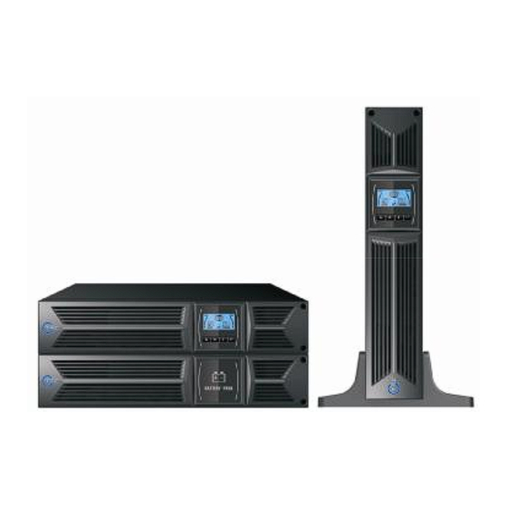
USER MANUAL
On-Line UPS
Model AP160N
1000VA/2000VA/3000VA
Uninterruptible Power Supply System
CONTENT
1. Safety and EMC Instructions ..............................................................4
1.1 Installation.............................................................................................4
1.1.4 EBM Installation (Optional)................................................................5
1.2 Operation ..............................................................................................9
1.3 Maintenance, servicing and faults ......................................................10
1.4 Transport.............................................................................................13
1.5 Storage ...............................................................................................13
1.6 Standards............................................................................................14
2. Description of Commonly Used Symbols .......................................15
3. Introduction.........................................................................................16
4. Panel Description ...............................................................................17
5. Connection and Operation ................................................................19
5.1 Inspection: ..........................................................................................19
5.2 Connection:.........................................................................................19
5.3 Battery charge: ...................................................................................21
5.4 Turn on the UPS: ................................................................................21
5.5 Test function:.......................................................................................21
5.6 Turn off the UPS: ................................................................................22
5.7 Audible alarm mute function: ..............................................................22
("S" model)................................................................................................22
6. Operating Mode for All Models .........................................................24
6.1 Line mode ...........................................................................................24
6.2 Battery mode ......................................................................................25
6.3 Bypass mode ......................................................................................25
6.4 NO output mode .................................................................................26
6.5 EPO (Emergency Power Off) .............................................................26
6.6 ECO mode (Economy mode) .............................................................26
6.7 Converter mode..................................................................................27
6.8 Abnormal mode ..................................................................................27
7. Setting by LCD Module ......................................................................28
8. Trouble Shooting................................................................................30
9. Maintenance........................................................................................32
Advertisement
Table of Contents

Related Manuals for TEC AP160N Series 1000VA


Summary of Contents for TEC AP160N Series 1000VA
-
Page 1: Table Of Contents
CONTENT 1. Safety and EMC Instructions ..............4 1.1 Installation.....................4 1.1.4 EBM Installation (Optional)..............5 1.2 Operation ....................9 1.3 Maintenance, servicing and faults ............10 USER MANUAL 1.4 Transport.....................13 1.5 Storage ....................13 1.6 Standards....................14 On-Line UPS 2. Description of Commonly Used Symbols ........15 3. -
Page 2: Safety And Emc Instructions
1. Safety and EMC Instructions 9.1 Operation ....................32 9.2 Storage ....................32 9.3 Battery Replace ..................32 Please read carefully the following user manual and the safety 10. Technical Data...................33 instructions before installing the unit or using the unit! 10.1 Electrical specifications ..............33 1.1 Installation 10.2 Operating Environment..............33 ★... -
Page 3: Ebm Installation (Optional)
l Rack-mount setup 1.1.2 Unpacking the Cabinet To unpack the system: The series can be installed in 19 inches racks. Both the UPS and external Open the outer carton and remove the accessories packaged with the battery enclosure need 2U of valuable rack space. cabinet. - Page 4 on side of the front panel to allow the outlet wire of the EBM to pass through Connecting the EBM in a rack form the gate and then reassemble front panel. 1. Using the same method as assembling UPS in a rack form, assemble EBM into the rack-mounting on the top or bottom of the UPS.
-
Page 5: Operation
Connecting multiple EBMs in Tower form 1. Connect Earth line between UPS and the first EBM, and then connect Earth Line between the first EBM and the second EBM. 2. Take off the front panel, and connect the battery terminal (A) from UPS to EBM terminal (B) shown as below. -
Page 6: Maintenance, Servicing And Faults
with a vacuum cleaner. For long battery life, keep the UPS at an ambient Torque force when connecting to terminal block. temperature of 25°C (77°F) ★ Use No. 10AWG (for all models battery wire), 90°C copper wire and Anderson PP45 connectors for user’s external battery cabinet. 1.3 Maintenance, servicing and faults 1.3.2 Storing the UPS and Batteries ★... -
Page 7: Transport
1.3.5 Testing New Batteries Note: If you are not qualified service personnel to replace the battery, do not For a battery test, please check: attempt to open the battery cabin. Please call local dealer or distributor The batteries must be fully charged. immediately. -
Page 8: Standards
2. Description of Commonly Used Symbols 1.6 Standards Some or all of the following symbols may be used in this manual. It is advisable to * Safety familiarize yourself with them and understand their meaning: IEC/EN 62040-1-1 * EMI Conducted Emission......:IEC/EN 62040-2 Category C1 Radiated Emission......:IEC/EN 62040-2 Category C1... -
Page 9: Introduction
3. Introduction 4. Panel Description This On-Line-Series is an uninterruptible power supply incorporating double-converter technology. It provides perfect protection specifically for Novell, Windows NT and UNIX servers. The double-converter principle eliminates all mains power disturbances. A rectifier converts the alternating current from the socket outlet to direct current. -
Page 10: Connection And Operation
5. Connection and Operation The system may be installed and wired only by qualified electricians in accordance with applicable safety regulations! When installing the electrical wiring, please note the nominal amperage of your incoming feeder. 5.1 Inspection: The LCD Display Inspect the packaging carton and its contents for damage. -
Page 11: Battery Charge
5.3 Battery charge: (2) UPS Output Connection Fully charge the batteries of the UPS system by leaving the UPS system The output of the UPS is IEC socket-types. Simply plug the load power cord connected to the mains for 1-2 hours. You may use the UPS system directly to the output sockets to complete connection. -
Page 12: Turn Off The Ups
all model. And battery wire color is recommended as following: 5.6 Turn off the UPS: + - (1) In Inverter Mode: Red wire Green/Yellow wire Black wire Press “ ” button continuously for more than 1 second to turn off the UPS, the (6) The red wire is connected to the "+"... -
Page 13: Operating Mode For All Models
6. Operating Mode for All Models Note: Please follow the following steps to connect the generator: Activate the generator and wait until the operation is stable before The different string could be displayed on the LCD screen corresponding to supplying power of the generator to the UPS (be sure that the UPS is in their own operating modes, and they are illustrated as the following table. -
Page 14: No Output Mode
6.7 Converter mode The UPS does not have the backup function when it is in bypass mode. The power used by the load is supplied from the utility power via internal In converter mode, on LCD display, the mode string is “CVCF”. filter. -
Page 15: Setting By Lcd Module
7. Setting by LCD Module several seconds after “Bypass Enable” is selected, and turn to no output mode in several seconds after “Bypass Disable” is selected; Operating mode could The output voltage, frequency, Bypass status and operating mode in No output be selected in “UPS”, “ECO”, “CVF”(Here “UPS”... -
Page 16: Trouble Shooting
8. Trouble Shooting Charge fail The charge is broken Notify dealer. Inverter temperature high Inside temperature of the UPS Check the ventilation of the UPS, is too high check the ambient temperature. If the UPS system does not operate correctly, check the operating status on the LCD Ambient temperature high The ambient temperature is Check the environment ventilation. -
Page 17: Maintenance
9. Maintenance 10. Technical Data 9.1 Operation 10.1 Electrical specifications The UPS system contains no user-serviceable parts. If the battery service life INPUT (3~5 years at 25°C ambient temperature) has been exceeded, the batteries Model No. 1K & 1K-KS 2K & 2K-KS 3K &... -
Page 18: Dimensions And Weights
10.4 Dimensions and weights 11.2 RS-232 port Model 1K-KS 2K-KS 3K-KS The RS-232 port is available for UPS monitoring, control, and firmware updates. To establish communication between the UPS and a computer, Net weight (kg) 16,2 19,7 28,6 13,2 connect one end of the serial communication cable that comes with the UPS to Cabinet Dimension (mm) the RS-232 port on the UPS. -
Page 19: Software
12. Software Note: You do not have to shut down the UPS before you install a communication card. Free Software Download – WinPower To install the Network Management Card, complete the following steps: WinPower is a brand new UPS monitoring software, which provides user-friendly interface to monitor and control your UPS. -
Page 20: Appendix: Rear Panel
Appendix: Rear panel The UPS rear panel description table and pictures are shown as below: Function(1KVA – 2KVA – 3KVA) AC Output EPO / Dry input Communication Port USB Port AC Input Dry out SNMP slot 3K Standard model rear panel RS232 Modem/Network Surge Protection Earth Line connection...
Need help?
Do you have a question about the AP160N Series 1000VA and is the answer not in the manual?
Questions and answers