Table of Contents
Advertisement
Displays
Programmable displays with a wide se-
lection of inputs and outputs for display of temperature,
volume and weight, etc. Feature linearisation, scaling,
and difference measurement functions for programming
via PReset software.
Ex interfaces
Interfaces
for
analogue
signals as well as HART
®
signals between sensors / I/P
converters / frequency signals and control systems in Ex
zone 0, 1 & 2 and for some modules in zone 20, 21 & 22.
Isolation
Galvanic isolators for analogue and digital
signals as well as HART
signals. A wide product range
®
with both loop-powered and universal isolators featuring
linearisation, inversion, and scaling of output signals.
Temperature
A wide selection of transmitters for DIN
form B mounting and DIN rail modules with analogue
and digital bus communication ranging from application-
specific to universal transmitters.
Universal
PC or front programmable modules with
universal options for input, output and supply. This range
offers a number of advanced features such as process
calibration, linearisation and auto-diagnosis.
and
digital
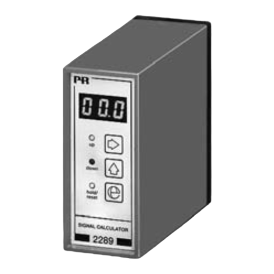
2 2 8 9
S i g n a l C a l c u l a t o r
N o . 2 2 8 9 V 1 0 1 - I N ( 1 0 1 5 )
F r o m s e r . n o . 9 8 0 3 3 8 0 0 1
S I G N A L S T H E B E S T
Side 1
DK
Page 35
UK
Page 69
FR
Seite 103
DE
Advertisement
Table of Contents

Summary of Contents for PR electronics 2289
- Page 1 Displays Programmable displays with a wide se- lection of inputs and outputs for display of temperature, volume and weight, etc. Feature linearisation, scaling, and difference measurement functions for programming via PReset software. Ex interfaces Interfaces analogue digital signals as well as HART ®...
-
Page 2: Table Of Contents
SIGNAL CALCULATOR Type 2289 CONTENTS Declaration of Conformity ..........36 How to dismantle SYSTEM 2200 ........37 Application ................. 38 Technical characteristics ............ 38 Functions: Analogue calculator ............38 Sample-Hold ..............38 Peak-Hold ..............39 Delay ................39 PID controller ..............39 Manual / automatic controller ........ -
Page 3: Declaration Of Conformity
DECLARATION OF CONFORMITY HOW TO DISMANTLE SYSTEM 2200 As manufacturer PR electronics A/S Picture 1: The back panel of the module is Lerbakken 10 detached from the housing by way DK-8410 Rønde of a screwdriver. hereby declares that the following product:... -
Page 4: Application
The digital input is used to change between the manual and automatic mode. In • multiplexer. The 2289 Signal Calculator will meet the demands of any process the auto matic mode the analogue output follows input A. When changing to the engineer with an unexpected or special signal processing assignment at hand. -
Page 5: Analogue Multiplexer
DIGITAL INPUT - 2289A Differentiating time (TD) ......0...999 s By way of JP6 the 2289 signal calculator can be programmed to NPN (pull up to Response time ......... < 60 ms 24 VDC), or PNP (pull down to 0 VDC). Min. pulse length is 50 ms. - Page 6 Cable resistance per wire (max.) ....25 Ω Sensor current ........... Nom. 1.25 mA Response time .......... < 100 ms Basic accuracy .......... < ±0.2°C ORDER: 2289 Temperature coefficient: span < 100°C .......... < ±0.01°C/° C amb. span > 100°C .......... < ±0.01% of span/°C amb.
- Page 7 BLOCK DIAGRAM -2289A: BLOCK DIAGRAM -2289B:...
-
Page 8: Hardware Programming
HARDWARE PROGRAMMING: JUMPER POSITIONING: INPUT: Channel A 0...20 mA MENU 2.3 = I 0...10 VDC MENU 2.3 = U Channel B 0...20 mA MENU 3.3 = I 0...10 VDC MENU 3.3 = U OUTPUT: EXTERNAL UP / DOWN OPERATION OF MANUAL CONTROLLER: Output MENU 4.3 0...10 mA... -
Page 10: Routing Diagram
3 Fast setting short cut key PROGRAMMING / OPERATING When the PID controller with an internal setpoint has been selected, a THE FUNCTION KEYS fast setting is possible by way of the Fast Setting function. In this menu the function keys have a special function as 3 downcounts the setpoint and 1 upcounts the setpoint from the value it had when activated. - Page 11 1.3 P3 - Calculation offset. 1.5 HLd - Hold of signal on input A. A typical value is 0.0. When the digital input is active, the input signal is held at the value it Valid selections are -99...999. [Factor] had when activated. Possible selections are EnA [Enable hold], or dSA [Disable hold].
- Page 12 1.2 CH - Input. 1.8 PUP - Integration value at power on. Possible selections are A or B. [Input] When - rES - has been selected, the integration value is reset at power on. When - HLd - has been selected, the integration value present 1.0 PAr for PID controller.
- Page 13 1.3 IE - Internal / external signal limiter. A typical value is 5.0, but the degree should be adapted to the present When - I - has been selected, the other analogue input is disabled, and application. the signal limiting follows the set IL and IH values. Valid selections are -99...100.
- Page 14 2.2 IAH - Setting of 100% input signal. 003 = voltage output in the range 0...500 mV Valid selections are current 0.0...20.0 [mA], or voltage 0.0...10.0 [VDC]. 004 = voltage output in the range 0...1 V (for instance 0.2...1 V) For modules with a Pt100 input, the valid 100% temperature is 005 = voltage output in the range 0...5 V -99...+850 [°C].
- Page 15 When calculating scale factors the input and output signal spans obtained. Therefore it is important that the the proportional band Xp, always have values between 0 and 1. When adding 2 identically scaled the integrating time Ti, and the differentiating time Td are adjusted input signals of for instance 4...20 mA, the output would be 8...40 mA according to the present application.
- Page 16 has 2 parameter settings, AtI - averaging time, and StS - number 016 = Analogue multiplexer: of memories. The averaging time is the time that is averaged. The Expression: (P1*A) and (P2*B). The input (A or B) to be transferred to the output is selected by the number of memories to be selected is (1...14).
Need help?
Do you have a question about the 2289 and is the answer not in the manual?
Questions and answers