
Related Manuals for AvMap Ultra EFIS

Summary of Contents for AvMap Ultra EFIS
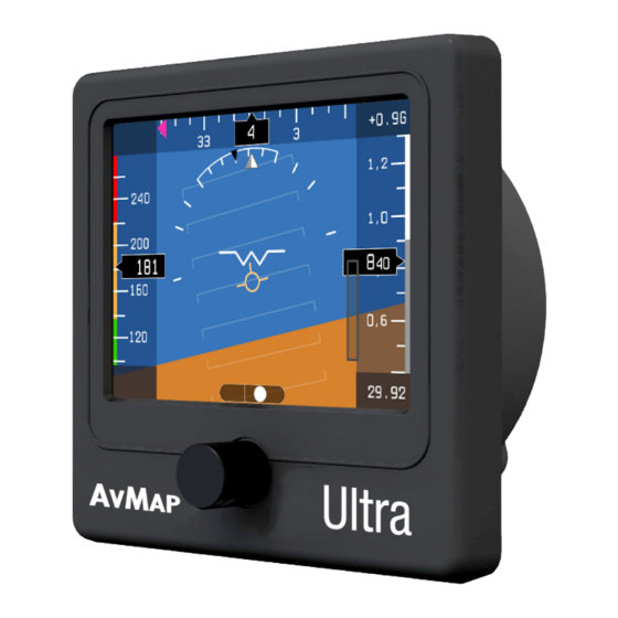
- Page 1 EFIS Ultra Software: version 5.6 and higher Firmware: version 3.15 User and Installation Manual Your journey, Our technology...
-
Page 3: Table Of Contents
DISCLAIMER & WARNINGS The information displayed by the Ultra EFIS is not certified for use for VFR or IFR flights. The Ultra EFIS is meant as an aid to VFR navigation and is not a substitute for certified EFIS. All critical flight information is presented for reference only and must be verified by the use. -
Page 4: Overview
GPS receiver Connecting the external GPS receiver to the Ultra EFIS, the system provides the pilot with navigation information on the HSI page , providing its position, direction and radials relative to reference navigation points. -
Page 5: Installation
Ultra EFIS Micro SD card A microSD card is included in the Ultra EFIS box. The microSD card is a blank card without data preloaded. The microSD card should be used for Software updates and data transfer from/to the Ultra EFIS like updating the Navdata POI’s. - Page 6 AvMap Ultra EFIS The Ultra EFIS is designed to be installed in an 3.3” (84mm) diameter hole. The instrument has to be installed from the front of the panel and screwed from behind the panel according to Figure 3. Ultra Ultra 11.5...
-
Page 7: User And Installation Manual
Make sure you respect the screw length formula to avoid damaging the plastic of the Ultra EFIS. Use light thread locker to prevent screw loosening with vibration. Use the Cutting template, included in the box, to cut out the panel. (see Figure 4) -
Page 8: Connections & Wiring
Figure 5 the bo Connection to the pitot-static system In order to display accurate speed and altitude data the Ultra EFIS needs to be connected suppl the 1A to the aircraft pitot-static system. First of all remove the two caps protecting the STATIC to pro and PITOT ports. - Page 9 External GPS receiver connection Connect the external GPS receiver, included in the box, on the back side of the Ultra EFIS to the GPS port as shown on Figure 5. The GPS receiver comes with a 1,5 meter cable and is designed for use inside the aircraft.
-
Page 10: System Calibration
Figure 7 Scenario B - Horizon Alignment Calibration required In case the Ultra EFIS is installed in an instrument panel that is aligned with the aircraft lateral axis, but not perpendicular to the straight & level flight attitude, the simple Horizon Alignment calibration procedure must be executed. -
Page 11: Magnetometer (Compass) Calibration
RED and is out of order. IMPORTANT: Before you proceed with the magnetometer (compass) calibration, make sure that the horizon line of the Ultra EFIS is aligned with the aircrafts straight & level flight attitude (see paragraph 3.1) - Page 12 Set the aircraft in level and straight flight attitude by using jacks or blocks. Note: Make sure that the Horizon line of the Ultra EFIS is aligned with the aircrafts straight & level flight attitude.
-
Page 13: System Operation
Note: If the calibration fails or the compass indicator is not enabled, repeat the calibration procedure. If several calibration attempts fails review the installation location of the Ultra EFIS. Magnetic disturbance could be too high in the area selected. 4. System Operation 4.1 How to operate the unit... - Page 14 All prints are in WHITE All prints are in WHITE AvMap Ultra EFIS SETUP CALIBRATE DATABASE Ultra Ultra V AP V AP Setup Menu PFD Menu Figure 8 While in PFD mode, pushing once the rotation knob an option menu window appears on the display.
-
Page 15: Pfd Mode
AvMap Ultra EFIS 4.2 PFD mode The PFD shows critical flight information like attitude, airspeed, altitude, as well as other less critical flight variables like turn coordination, heading, load factor. A detailed explanation of each instrument is given in Figure 9. - Page 16 QNH Setting When the Ultra EFIS is in Primary Flight Display mode the pressure reference for the altimeter can be selected by pushing the rotation knob. Select QNH to enter the QNH menu.
-
Page 17: Hsi Display Mode
AvMap Ultra EFIS List of available reference values V-speed values Never to exceed speed Maximum cruise speed Stall speed with flaps & landing gear deployed Maximum flaps extended speed Stall speed with flaps & landin gear retracted 4.3 HSI display mode The HSI shows navigation data: position, distance, directions, and radials relative to reference navigation points. - Page 18 POI ID, distance (in nm, km or miles), POI name, and two lines of miscellaneous textual information (frequencies and runways for airports, for example). HSI settings When the Ultra EFIS is in HSI display mode press the rotation knob to enter the HSI mode menu. Select HSI to enter the HSI menu: In the HSI menu you can select an Airport (ARPT), VOR and NDB as your navigation point.
-
Page 19: Setup Mode
When you purchase an update, you’ll receive a navdata file. Save the navdata file on your PC and copy it on the microSD card. To import the navdata update from the microSD to the Ultra EFIS insert the microSD in to the device, go to the Database menu and select IMPORT. -
Page 20: Software Update
Turn the Ultra EFIS ON providing power supply to the device. A message will show on the display: “COPY NEW BINARY?”. Push once the rotation Knob and select “YES” to update the Ultra EFIS with the new Software, or select “NO” if you don’t want to proceed with the update. - Page 21 Ultra EFIS GPS failure During the Ultra EFIS start-up and until a GPS fix is acquired, the GPS position field on the HSI display will indicate GPS error in RED. If the GPS fails during operation, the same condition is indicated. The unit can continue calculating position with degraded precision in absence of GPS.
-
Page 22: Technical Specifications
The first two causes can be solved by updating the software with the latest available software version. If a software update doesn’t resolve the failure the Ultra EFIS requires service at AvMap facility. - Page 24 EFIS Ultra www.avmap.it www.avmap.us MAEFSAM0AE030 www.avmap.com.br ÑMAEFSAM0AE030nÓ...
Need help?
Do you have a question about the Ultra EFIS and is the answer not in the manual?
Questions and answers