Table of Contents
Advertisement
Quick Links
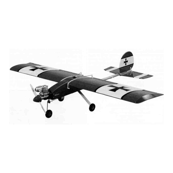
Wingspan:
Wing Area:
Fuselage Length:
Radio Required:
READ THROUGH THIS INSTRUCTION MANUAL BEFORE STARTING CONSTRUCTION. IT CONTAINS
IMPORTANT INSTRUCTIONS AND WARNINGS CONCERNING THE ASSEMBLY AND OPERATION OF
THIS MODEL.
DuraPlane guarantees this kit to be free from defects in both material and workmanship at the date of purchase.
This warranty does not cover any component parts damaged by use or modification. In no case shall
DuraPlane's liability exceed the original cost of the purchased kit. DuraPlane reserves the right to change or
modify this warranty without notice.
DuraPlane
Printed in USA DURA1140
Assembly Instructions
Specifications:
56 in (1422 mm)
594 sq in (37.9 sq dm)
49 in (1117.6mm)
4-Channel with 4 servos
P.O. Box 788
Weight:
Engine Required:
2-stroke .40 to .46 engine w/muffler, or
4-stroke .48 to .52 engine
Urbana, IL61803
(217)398-8970
5.5 to 6 lb (2743 g)
ENTIRE CONTENTS © 1997
Advertisement
Table of Contents

Related Manuals for DuraPlane DuraStik 40


Summary of Contents for DuraPlane DuraStik 40
-
Page 1: Assembly Instructions
IMPORTANT INSTRUCTIONS AND WARNINGS CONCERNING THE ASSEMBLY AND OPERATION OF THIS MODEL. DuraPlane guarantees this kit to be free from defects in both material and workmanship at the date of purchase. This warranty does not cover any component parts damaged by use or modification. In no case shall DuraPlane's liability exceed the original cost of the purchased kit. - Page 2 Electric drill fun flying DuraPlane model Because the DuraStik 40 is fully Drill Bits 1/16", 3/32", 7/64", 1/8", 5/32", aerobatic featuring a wing that has no dihedral (and does not #19 (or 11/64"), 3/16", 15/64"...
- Page 3 Medium silicone fuel tubing (GPMQ4131) Refer to the Parts List for a description of the parts and #64 Rubber bands (HCAQ2030) hardware included with the DuraStik 40 kit 1/4" R/C foam rubber sheet (HCAQ1000) 3/4" Wide fiber reinforced strapping tape 1/16"...
- Page 4 blade to cut the hinge slots in the center of the fin TE and the center of the rudder LE at the locations you marked. 1. Test fit the shaped 1/4" balsa fin front to the shaped 1/4" balsa fin rear as shown in the following photo. If necessary, true the joining edges with a bar sander and 150-grit sandpaper so there is no gap between the two pieces.
- Page 5 2. Glue the stab front to the stab rear with medium CA. 7. Mount a control horn to the top of the elevator with two From now on we will call this assembly the stab. Use 2-56 x 1/2" screws and the horn plate. Position the edge of 150-grit sandpaper and a sanding block to round the the horn base 8-7/16"...
-
Page 6: Mount The Engine & Install The Fuel Tank
3. Place the fuse channel on the bottom of the stab (on the 1/16" ply bottom plate). Align the centerline you drew on the stab bottom plate with the holes in the bottom of the fuse channel and align the trailing edge of the stab with the aft edge of the fuse channel. - Page 7 secure. Position your engine on the mount and mark the location of the mounting holes. Hint: Sharpen the end of a 1/16" wire rod to a point. Heat the rod with a lighter and use it to mark the mounting holes on the engine mount.
-
Page 8: Mount The Landing Gear
into the fuselage, making sure the hole for the throttle pushrod is in the correct orientation Tightly tape the firewall in place with masking tape Confirm that the locations of the holes will not interfere with the throttle pushrod If they do, adjust the locations of those holes Drill holes through the fuselage and into the firewall with a 3/32"... - Page 9 CUT OFF 6. Drill the hub of two 2-1/2" main wheels with a #19 (or UNUSED 11/64") drill. Secure each wheel to the landing gear with an ARMS 8-32 x 1-1/4" cap screw and two 8-32 nuts as shown in the photo.
- Page 10 THREADED STUD 1. Thread a nylon clevis onto a 1" threaded stud about 20 full turns. Thread the other end of the stud about 1/2" into a 36" inner pushrod tube. Connect the clevis to the control horn on the elevator and slip a 36" grey outer 6.
- Page 11 Refer to this photo for the next two steps. 2. Secure the nose wheel steering outer pushrod guide tube to the bottom of the fuse with two nylon pushrod clamps and two #6 x 1/2" screws. Position the front pushrod clamp so the pushrod aligns with the nose wheel steering arm.
- Page 12 Make a dry run of the following three steps so you can gather all the items you'll need and to make sure you understand how to join the wing halves. Note: We used aliphatic resin (wood worker's glue such as Great Planes Pro wood glue) to glue the wing together.
- Page 13 Shape the TE to match the wing. 5. Apply glue to the top spar notches and the notches where the wing joiner fits. Apply glue to the wing joiner. Insert the wing joiner into the wing. 2. After the glue dries, use a razor saw to cut the spars and TE'S so they are even with the tips of the wing.
- Page 14 1/8" PLYWOOD SERVO RAILS 5 Mark the locations of the hinges on the aileron and the trailing edge of the wing as shown in the sketch Cut the hinge slots and temporarily join the ailerons to the wing 1 Temporarily place the die-cut 1/8" plywood servo with the hinges to make sure the hinge slots align Make rails in the top of the wing Position your aileron servo in adjustments if required...
- Page 15 7 Mount both control horns to the ailerons with two 2 56 3 Bevel the TE of the wing saddle with a bar sander x 1/2" screws and the mounting plate you cut from the and 150-grit sandpaper so it will not interfere with the control horn The edge of the horns should be 1/4"...
- Page 16 One six foot roll will be enough to cover the DuraStik but, if you wish to add trim colors or other designs, you will have to purchase more than one roll Covente also offers graphics, numbers, stars and lettering 1 Disconnect the elevator and rudder pushrods from the tail surfaces and remove the control horns and hinges Remove the stabilizer and fin from the fuselage channel If you haven t already done so, final-sand all the tail surfaces...
- Page 17 rearward or downward Overlap the lines you drew on the top of the wing for the wing shield by 1/4" Leave the rest of the foam exposed for a good glue bond to the wing shield. Cover the tail in the following order: 1.
- Page 18 not have a C G Machine, lift the model with your fingers at the C G point (mark the C G on the bottom of the wing with a felt tip pen or a piece of tape so you know where to lift) Position the battery pack on the fuse until the model is level This is the position where you should mount the battery pack inside the fuselage Try to position the battery...
- Page 19 Before You Go to the Flying Field 4-CHANNEL RADIO SETUP (STANDARD MODE 2) The DuraPlane DuraStik 40 is intended for intermediate to ELEVATOR MOVES UP expert level pilots although beginners can have success with the DuraStik if they have had some time on a trainer model.
-
Page 20: Flight Log
C G may be too far aft Add some weight to DuraPlane P.O. Box 788 the nose if this is the case At a high altitude, throttle back...
Need help?
Do you have a question about the DuraStik 40 and is the answer not in the manual?
Questions and answers