
Summary of Contents for Electromaten TS 959
- Page 1 Installation instructions Door control TS 959 51171547_d_03_2014 0 0 0 0 0 0 0 0 0 0 0 5 1 1 7 1 5 4 7 XXXXX...
- Page 2 GfA - Gesellschaft für Antriebstechnik GmbH Wiesenstraße 81 D-40549 Düsseldorf www.gfa-elektromaten.de info@gfa-elektromaten.de...
-
Page 3: Table Of Contents
Table of contents General safety information .................... 5 Technical data ......................6 Mechanical installation ....................7 Electrical installation ..................... 8 Cable connection overview ....................9 Limit switch assignment for screwable version until year of manufacture of 1997 ..10 ... - Page 4 Functional description ....................23 X1: Mains supply line for control and external supply ............. 23 X5: Input, control device ....................24 Advanced hold-to-run function ..................24 X20: Floating relay contact ....................25 Force monitoring (DES only) ................... 25 ...
-
Page 5: General Safety Information
1 General safety information Specified normal use The door control is intended for a power-operated door with a drive unit. The safe operation is only guaranteed with normal specified use. The drive unit is to be protected from rain, moisture and aggressive ambient conditions. No liability for damage caused by other applications or non-observance of the information in the manual. -
Page 6: Technical Data
2 Technical data Series TS 959 Dimensions W x H x D 155 x 386 x 90 Assembly vertical Assembly Vibration free of vibration Operating frequency 50/60 1 N~220 V, PE Supply voltage (+/- 10%) 3 N~220-400 V, PE 3~220-400 V, PE... -
Page 7: Mechanical Installation
3 Mechanical installation Control installation! Only use indoors Mounting only on a level ground free of vibration Only vertical mounting position permissible Door must be visible from the assembly site Prerequisites The permissible loads of walls, mountings, connecting and transmission elements must not be exceeded. -
Page 8: Electrical Installation
4 Electrical installation Warning - Risk of electrocution! Disconnect the cables and check that they are de-energised Observe the applicable regulations and standards Make a proper electrical connection Use suitable tools On-site backup fuse and disconnector unit! ... -
Page 9: Cable Connection Overview
Cable connection overview DES and NES DES connection cable for limit switch motor connection cable X13 Motor plug X12 Limit switch plug Core Term. Core Term. Phase W 5/wh +24 V safety circuit Phase V 6/bn Channel B (RS485) Phase U 7/gn Earth Neutral conductor (N) -
Page 10: Limit Switch Assignment For Screwable Version Until Year Of Manufacture Of 1997
Limit switch assignment for screwable version until year of manufacture of 1997 4 (N) Thermal contact Limit switch board Rectifier Emergency open limit switch Motor Emergency close limit switch Emergency manual operation Open limit switch Connection cable Close limit switch Spring-loaded brake Auxiliary limit switch Auxiliary limit switch... -
Page 11: Carrying Out The Electrical Installation
Carrying out the electrical installation ▶ Remove coverings. ▶ Open cable entry ① or ②. ▶ Insert and connect control – drive connection cable in the open cable entry ① (from below) or ② (from above). ▶ Tighten cable gland. Caution –... -
Page 12: Mains Connection
Mains connection 3~, N, PE 3~, PE 1~, N, PE, sym. 1~, N, PE, asym. 190 – 440 V 190 – 440 V 190 – 230 V 190 – 230 V 50 -60 Hz 50 -60 Hz 50 -60 Hz 50 -60 Hz L1 L2 L3 N PE L1 L2 L3... -
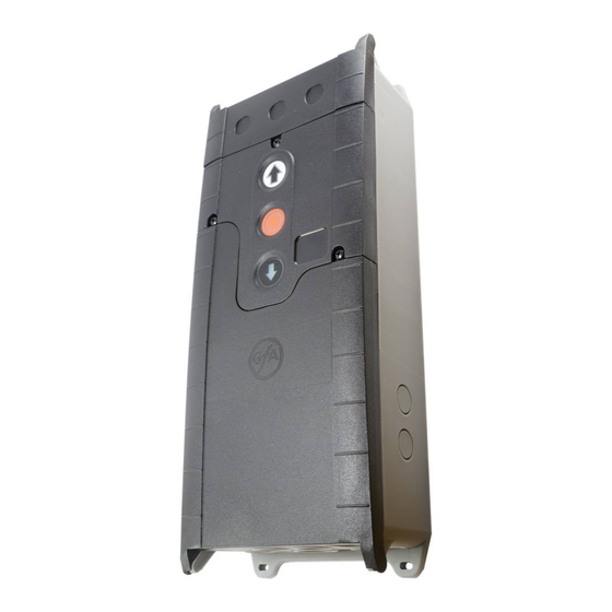
Page 13: Overview Of Control Panel
Overview of control panel DES/ 5.1 5.25.3 5.4 F1 = 1,6A t Mains supply DES/ DES or NES limit switch socket Door safety switch 1.6-A micro-fuse with time delay Emergency stop button Motor socket Control device, external three push button Selector switch Floating relay contact “Open”... -
Page 14: Initial Operation Of The Control
5 Initial operation of the control ▶ Plug in or switch on mains supply line DES: Rapid adjustment of final limit positions 1. Check rotating direction 2. Start OPEN final limit position 3. Save OPEN final limit position 4. Start CLOSE final limit position 5. -
Page 15: Nes: Rapid Adjustment Final Limit Positions
Read the drive unit mounting manual! Adjust the cam limit switch, see drive unit mounting manual NES: Rapid adjustment final limit positions 1. Check rotating direction 2. Move to OPEN final limit position and adjust S3 OPEN limit switch 3. -
Page 16: Advanced Electrical Installation
6 Advanced electrical installation External s upply X1 Emer gency stop X3 Relay contact X20 Relay contact X20 External supply X1 Emergency stop X3 Relay A1 External device A2 Control device Emergency stop Control device X5 Control device X5 A4 Key-switch A6 Three push button Open/Close locked Spiral cabl e c onnecti on... -
Page 17: Programming The Control
7 Programming the control 1. Only program after rapid adjustment of final limit positions! 2. Select and confirm the menu 3.a) Set and store functions 3.b) Set and save (DES) positions 4. Exit programming... -
Page 18: Table Of Menus
8 Table of menus Operati ng mode Operating mode Door operating mode OPEN Hold-to-run CLOSE Hold-to-run OPEN Self-hold CLOSE Hold-to-run Extended hold-to-run For NES: Set the S5 limit switch right before the Close position Output direction of rotation Maintain the output direction of rotation Change output direction of rotation Door positions Door positions... -
Page 19: Door Functions
Door functi ons Door functions Relay function on X20 Teach in door position via menu 1.7 (DES only) Pulse signal for 1 second Permanent signal Red lamp, permanent light during door movement OPEN final limit position 3 seconds permanent light CLOSE final limit position 3 seconds permanent light Red lamp, permanent light during door movement... -
Page 20: Maintenance Cycle Counter
Maintenanc e cy cle counter Maintenance cycle counter Maintenance cycle preselection 01-99 corresponds to 1,000 to 99,000 cycles Cycles are counted down Reaction on reaching zero "CS" display with set value of maintenance cycle Changeover to hold-to-run mode in OPEN direction, if door operating mode .2 has been set and "CS"... -
Page 21: Reading Out Memory
Reading out memory Reading out memory Cycle counter reading 7-digit number Cycle counter reading as coefficients of powers of ten from one million down to one 1,000,000 10,000 100,000 1,000 Last Fault The six most recent faults are indicated alternately Cycle counter reading of the last programming change 7-digit Cycle counter reading as coefficients of powers of ten from one million down to one... -
Page 22: Safety Devices
9 Safety devices X2: Input, door safety switch The door safety switch is installed on the door and connected to the door control via the spiral cable. Function type Reaction upon activation Switching contact broken: Door is stopped Slack-rope/Pass door Switching contact closed: Door is ready for operation Slack-rope/Pass door With the switch open and simultaneous move command from the final limit positions, the... -
Page 23: Functional Description
10 Functional description X1: Mains supply line for control and external supply Mains supply line for control Connection via terminals X1/1.1 to X1/1.4 and PE Various mains supply connections: 3 N~, 3~, 1 N~ for symmetric and asymmetric motors. 400 V mains = 1.5 - 1.6 wire link 230 V mains = 1.6 - 1.7 wire link Note! ▶... -
Page 24: X5: Input, Control Device
X5: Input, control device Warning! ▶ "Hold-to-run" door operating mode: The door must be fully visible from the operating point Note! ▶ Application without STOP push-button: Connect wire link X5.1 to wire link X5.2 Advanced hold-to-run function Menu: "0.1", function type: ".5". For the advanced hold-to-run function, the CLOSE button must remain pressed until the CLOSE door final position has been reached. -
Page 25: X20: Floating Relay Contact
X20: Floating relay contact The relay functions are described under menu item "2.7". Caution – Damage of components! Maximum current at 230 V AC 1 A and at 24 V DC 0.4 A We recommend using LED lamps ... -
Page 26: Travel Time Monitoring (Nes Only)
After exiting the programming, the door must carry out a complete opening and closing operation in self-hold. The force monitoring is a self-learning system which is effective from a opening width of 5 cm to approx. 2 m. Slow progressive changes, e.g. reduction of the spring torsion, are compensated automatically. -
Page 27: Maintenance Cycle Counter
Maintenance cycle counter Menu "8.5": A maintenance cycle can be set between "0" and "99,000" cycles; the adjustment is made in steps of one thousand. The maintenance cycle counter reduces by one each time the Open final limit position is reached. -
Page 28: Status Display
11 Status display Error Display: "F" and code Status Fault description Measures for fault correction code Check door safety switch. Terminals X2.1 – X2.2 open. Check whether the connection cable is Slack-rope switch/Pass door contact open. disconnected. DES safety circuit open. Check emergency manual operation. - Page 29 Error Display: "F" and code Status Fault description Measures for fault correction code Limit switch system has been changed without Reset the control via program "9.5". reset of the control Internal plausibility error. Error acknowledgement by next command. Triggering of the force monitoring. Check the mechanics of the doors for stiffness.
- Page 30 Commands Display: "E" and code Code Command description An Open command is present. X5.3 control inputs A Stop command is present. X5.2 control inputs A Close command is present. X5.4 control inputs...
- Page 31 Status indications Status Description display Preset value for maintenance cycle counter status reached. Point on left-hand side is not lit: Control circuit short-circuit or overloaded. Change of rotating direction activated, only possible at initial start-up. Change of rotating direction carried out, only possible at initial start-up. Teach-in Open final limit position.
-
Page 32: Explanation Of Symbols
12 Explanation of symbols Symbol Explanation Request: Read mounting manual Request: Check Request: Note Request: Note the setting of the menu below Default adjustment of the menu Default adjustment of the menu, value on the right Default adjustment of the minimum limit, dependent on drive Default adjustment of the maximum limit, dependent on drive Setting range Request: Chose menu or value, turn selector switch left or right... - Page 33 Symbol Explanation Request: Adjustment via built in push button OPEN/CLOSE, OPEN push button upwards; CLOSE push button downwards Request: Press STOP button once via built in push-button Request: Save, press stop-button once via built in push-button Request: Save, press STOP-button for three seconds via built in push-button Request: Reset the control, press stop-button for three seconds via built in push-button Request: Start door positions...
-
Page 34: Declaration Of Incorporation/Declaration Of Conformity
GfA – Gesellschaft für Antriebstechnik, hereby declare that the product specified in the following complies with the above-mentioned EU Directive and is only intended for installation in a door system. TS 959 Applied standards DIN EN 12453 Industrial, commercial and garage doors and gates...
Need help?
Do you have a question about the TS 959 and is the answer not in the manual?
Questions and answers