Table of Contents
Advertisement
FCC STATEMENT
Caution:
Any changes or modifications not expressly approved by the party responsible for compliance could void the user's authority to operate
this equipment.
This device complies with Part 15 of the FCC Rules. Operation is subject to the following two conditions:
(1) This device may not cause harmful interference, and
(2) this device must accept any interference received, including interference that may cause undesired operation.
This device and its antenna(s) must not be co-located or operating in conjunction with any other antenna or transmitter.
NOTE:
This equipment has been tested and found to comply with the limits for a Class B digital device, pursuant to Part 15 of the FCC
Rules. These limits are designed to provide reasonable protection against harmful interference in a residential installation. This
equipment generates, uses and can radiate radio frequency energy and, if not installed and used in accordance with the instructions,
may cause harmful interference to radio communications. However, there is no guarantee that interference will not occur in a
particular installation.
If this equipment does cause harmful interference to radio or television reception, which can be determined by turning the equipment off
and on, the user is encouraged to try to correct the interference by one or more of the following measures:
-- Reorient or relocate the receiving antenna.
-- Increase the separation between the equipment and receiver.
-- Connect the equipment into an outlet on a circuit different from that to which the receiver is connected.
-- Consult the dealer or an experienced radio/TV technician for help.
AEI PROTECT-ON SYSTEMS LIMITED
www.apo-hk.com
VERSION: 01/2015
Self-Contained
Access Control Reader
OR-ZS-805
AR-2808
User Manual
Advertisement
Table of Contents

Summary of Contents for Orno OR-ZS-805
- Page 1 If this equipment does cause harmful interference to radio or television reception, which can be determined by turning the equipment off and on, the user is encouraged to try to correct the interference by one or more of the following measures: OR-ZS-805 AR-2808 -- Reorient or relocate the receiving antenna.
-
Page 2: Table Of Contents
TABLE OF CONTENTS ........................3 INTRODUCTION ........................3 SPECIFICATIONS ........................ 3 Package Contents ........................ 4 THE FRONT PANEL ......................4 Status Indicator (Blue) ......................4 Operation Indicators ......................4 Card Reader Window ..................4 Door Bell Button (Function Selector) ........................5 INSTALLATION .................. -
Page 3: Introduction
AR-2808 is a self-contained access control reader designed to drive electric door lock directly. It Description OR-ZS-805 accommodates up to 500 proximity EM cards and its output is compatible with the Fail-safe and The AR-2808 is expandable to a multi-station system for user convenience with the auxiliary OR-ZS-805 Fail-secure electric locks. -
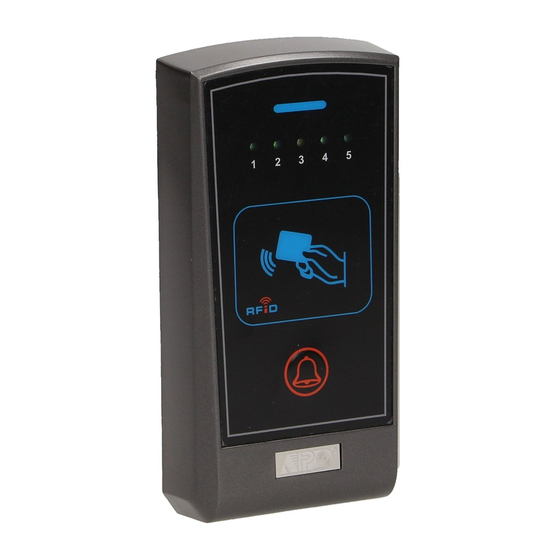
Page 4: The Front Panel
THE FRONT PANEL APPLICATION EXPANSION – The Optional Auxiliary Reader AR-2802 Apart from standard-alone operation, AR-2808 is expandable to be a Multi-station System with the OR-ZS-805 AR2808 FRONT PANEL optional auxiliary reader AR-2802. Maximum three optional readers can be allowed and the connection is very simple. -
Page 5: Installation
APPLICATION EXAMPLES INSTALLATION 1) Stand Alone Access Control Electric Lock AR-2808 ASSEMBLY AR-2808 ( + ) ( – ) ( + ) ( – ) DATA DOOR BELL TAMPER 12VDC DOOR LOCK N.O. N.C. ( + ) 12 VDC AP-960 EGRESS BUTTON POWER AD-2312... -
Page 6: The Connection Terminals
THE CONNECTION TERMINALS ( + ) ( – ) ( + ) ( – ) DATA DOOR BELL TAMPER 12VDC DOOR LOCK N.O. N.C. 1 - 2 : 12VDC (Power Input Terminal) Connect (+), terminal 1 to a 12V DC power supply. The (-), terminal 2 is the common grounding point of the system. -
Page 7: Eg In (Egress Input For N.o. Button)
5 : EG IN (Egress Input for N.O. Button) A Normally Open (N.O.) input terminal referring to (-) ground for connecting N.O. button to activate the output contact for door lock strike. Egress button is usually put inside the house near the door for “request to exit”. -
Page 8: Create A Master Card (Cmc)
CREATE A MASTER CARD (CMC) OPERATION The First Step before Programming- Make A Master Card 1) Read User Card to Open Door ● The system needs a Master Card to set it into programming mode. Before programming, it is ● Read User Card once. iiIInecessary to make a Master Card by the owner. -
Page 9: Programming
B) Delete Super User Card(s) – Option 2 PROGRAMMING In case a Super Card is lost, it can be deleted from the system. 1) Criteria for Setting System to Programming Mode ● The system is in standby under Normally Operation Read Master Card 5 Times Select Select... -
Page 10: I ) Record User Card(S) - Feature Group 1
V ) CREATE / DELETE SUPER USER CARDS -- Feature Group 5 I ) RECORD USER CARDS – Feature Group 1 There are 5 Storage Groups available for storing total 500 User Cards. For easy management, each The Super User cards are prepared for the owner or the trustworthy executives, which have TWO functions that are system lock-up and door open. -
Page 11: Delete User Card(S) - Feature Group 2
IV ) SET SYSTEM SAFETY LOCK-UP -- Feature Group 4 II ) DELETE USER CARD(S) – Feature Group 2 The reader can be protected with safety lock-up to prevent trials with un-recorded cards. There are The User Card(s) can be removed from the system if it is not used or lost. Three deletion modes three options for owner’s selection. -
Page 12: Iii ) Set Output Mode For Door Lock -- Feature Group 3
III ) SET OUTPUT MODE FOR DOOR LOCK -- Feature Group 3 4) Read Master Card 1 Time to close Programming Mode. IIIIResponse : 2 Beeps confirm reader back to normal operation. The operation of the door lock output can be set to Start/Stop mode or 1 second to 60 seconds Timing Mode.
Need help?
Do you have a question about the OR-ZS-805 and is the answer not in the manual?
Questions and answers