Table of Contents
Advertisement
Advertisement
Table of Contents

Summary of Contents for Simco-Ion AeroBar 5225S
- Page 1 Digital AeroBar ® Ionization System Model 5225S User’s Manual...
- Page 2 Simco-Ion is a division of Illinois Tool Works (ITW) with its Technology Group located in Alameda, California. For more information about Simco-Ion visit www.simco- ion.com or call 800-367-2452. Simco-Ion is ISO 9001 and ANSI ESD S20.20 certified. © 2012 Simco-Ion...
- Page 3 Important Safety Information Failure to follow these important safety cautions could result in damage to Digital AeroBar System components and voiding of your system warranty. Use proper input voltage to avoid damaging the unit. Verify that the AeroBar is not powered before connecting or removing cables.
-
Page 4: Table Of Contents
Contents 1 Description ................. 1 1.1 Overview ....................2 1.2 Remote Control..................5 1.3 Power Requirements ................7 2 Installation ................9 2.1 Mounting ....................11 2.2 Wiring..................... 13 2.3 FMS Connection ................... 17 2.4 Daisy-chaining ..................17 3 Operation ................. 19 3.1 About AeroBar Adjustments.............. -
Page 5: Description
Description 1.1 Overview 1.2 Remote Control 1.3 Power Requirements 19-5225S-M-01 Rev 2... -
Page 6: Overview
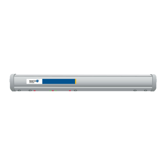
1.1 Overview The Digital AeroBar Model 5225S is specifically designed for use in a variety of applications, ranging from inside tools to work stations and cleanroom areas where digital performance with easy integration is desired. The Model 5225S operates as a standalone system with internally maintained settings. - Page 7 AeroBar Controls and Connectors Figure 1. AeroBar Model 5225S (Bar is longer than shown. The number of emitter points will vary per bar.) 1. Modular Port: A modular port on one end of the bar allows a RJ-11 connection to the 24 VAC power supply for the bar. 2.
- Page 8 Emitter points are replaceable. The number of points depends on the length of the bar. Length of Bar in Inches No. of Emitter Points 36 (2-load port configuration) 56 (3-load port configuration) 76 (4-load port configuration) Indicators Positive and Negative Ion Output Indicators These LEDs indicate high voltage (HV) ionization.
-
Page 9: Remote Control
1.2 Remote Control The Infrared Remote Control Model 5570 is used to communicate and set the power and timing parameters. Unlike a typical consumer remote control, the 5570 features a narrow infrared beam that prevents communication errors with nearby AeroBars. For best results, hold the remote control within 18-24 inches of an AeroBar’s vertical centerline and aim directly at the receive LED of the AeroBar. - Page 10 Passwords The Remote Control features two levels of access: a User Menu level, and a Technical Field Service (TFS) menu. • The User Menu level allows you to view current AeroBar settings, change the operation mode, change the positive and negative output levels, and set the on times and off times.
-
Page 11: Power Requirements
1.3 Power Requirements The AeroBar can be powered from any 24 VAC source using one of the following options: • Hard wire to a DIN rail mount transformer (p/n 14-21730) • Connect to DIN rail mount transformer through a junction box using an RJ-11 to RJ-11 interconnect cable (p/n 33-1700-xx) •... - Page 12 19-5225S-M-01 Rev 2...
-
Page 13: Installation
Installation 2.1 Mounting 2.2 Wiring 2.3 FMS Connection 2.4 Daisy-chaining 19-5225S-M-01 Rev 2... - Page 14 Important Safety Information Failure to follow these important safety cautions could result in damage to Digital AeroBar System components and voiding of your system warranty. Before installing or operating any components, carefully read the following safety information: After removing power from the AeroBar(s), allow a minute for the high voltage power supplies to discharge.
-
Page 15: Mounting
• The least amount of distance for cables from the Interface Module to AeroBars Clips Various mounting clips are available from Simco-Ion. In general: • Hold the bar to the grid or other structure and mark the locations where the mounting clips will attach. - Page 16 Flat metal clip (p/n 28-6255): Two required for 44” bars; three for 64", 76", and 84" bars. A polycarobante rod and clip assembly is also available #93-1420 (4”), 93-1421 (8”), 93-1422 (12”) Mid-clip for hang mount (p/n 28-6240): Use alone or in conjunction with end clips for bars over 44"...
-
Page 17: Wiring
The AeroBar can be directly wired to a 24 VAC source using wire terminations. Figure 3. Interconnect Cable Information Connection to the DIN Rail Mount Transformer The interconnect cable can be connected to the DIN Rail mount transformer (Simco-Ion p/n 14-21730) using either a bare wire 19-5225S-M-01 Rev 2... - Page 18 termination or an interconnect cable with an RJ-11 connector to a Junction Box (p/n 33-1825) wired to the transformer. (An RJ-11 connector is used at the AeroBar.) Direct Wire To wire directly to the transformer, use the wiring diagram shown in the figure below.
- Page 19 Figure 5. J-box Wiring Contact Simco-Ion for specific information on wiring the j-box (techsupport@ion.com or 510.217.0470). 19-5225S-M-01 Rev 2...
- Page 20 Connection to the Desktop Transformer Wiring to the 100/115/230 VAC switchable desktop transformer (Simco-Ion p/n 14-1535) requires an interconnect cable with an RJ- 11 4-wire connector at the AeroBar end and an RJ-22 4-wire connector at the transformer end. Pre-made interconnect cables with these connectors are available from Simco-Ion (p/n 33-1725- 10).
-
Page 21: Fms Connection
2.3 FMS Connection The AeroBar provides an FMS (facility monitoring system) output signal. The alarm is a non-isolated open collector that will pull the alarm pin to ground upon an alarm condition. See Figure 4 for the wire information. If connecting to the DIN Rail mount transformer, the FMS signal must be wired to your FMS system either by direct wire or through the junction box alarm wire. -
Page 22: Daisy-Chaining
2.4 Daisy-chaining Where AeroBars are used together in the same tool or in close proximity, it may be desirable to daisy-chain the AeroBars to the same power source. Up to 10 AeroBars can be daisy-chained together using standard interconnect cables in between the AeroBars. -
Page 23: Operation
Operation 3.1 About AeroBar Adjustments 3.2 Using the Remote Control 3.3 Ionization Mode (OpMode) 3.4 Output Voltages 3.5 On- and Off-times (Pulsed DC Mode Only) 3.6 FMS Alarm Values 3.7 Balance Adjustment and System Calibration 19-5225S-M-01 Rev 2... -
Page 24: About Aerobar Adjustments
3.1 About AeroBar Adjustments The following adjustments are available to operate and fine-tune ionization performance in a new installation: • Set the AeroBar ionization mode for each zone of operation • Set positive and negative output voltages • Set positive and negative ontimes and offtimes (pulsed DC mode only) •... -
Page 25: Using The Remote Control
3.2 Using the Remote Control Figure 8. Handheld Remote Control Power An on/off slide switch is featured on the right side of the remote control. Upon powerup, the remote control shows the following: UsrMenu Ver 2.6 Passwords Most menu items of the Remote Control require a password in order to be changed. - Page 26 Battery Life and Replacement The Remote Control uses two AA alkaline batteries. Life is approximately 60 hours for full operation, and approximately 500 hours while in sleep mode. If the battery voltage drops to ~2V, low battery will be indicated on the second line of the LCD display. Turn the remote control off with the slide switch to conserve battery life.
- Page 27 TFSMenu User Menu Hold down any button while turning the remote control on None Password and then: Esc, Down, Up, Select, Select, Select, Select. Status Status PosFdbk PosOut NegFdbk NegOut Address* OpMode PosOn PosOff PosOut Pos Alarm NegOn NegOff NegOut NegAlarm Viewable paramters...
- Page 28 Range is 0 to 100%. Address Not applicable with the Model 5225S AeroBar. The Remote Control is used with several models of Simco-Ion Digital AeroBars. OpMode Indicates the operating mode of the AeroBar, as follows: Standby: if the AeroBar is in standby. (AeroBar is powered but ionization is turned off.)
-
Page 29: Ionization Mode (Opmode)
3.3 Ionization Mode (OpMode) About Ionization Modes The AeroBar allows two different methods of ionization. Both are appropriate for different situations. Pulsed DC mode is recommended for process tool environments where the distance from the fan filter unit to the target exceeds 24 inches or where fast discharge is necessary. - Page 30 2. Enter in the following password: Esc, Down, Up, Select, Select, Select, Select. 3. Use the Up or Down button to reach the OpMode item. Press Select. 4. Point the remote control directly at the LEDs on the AeroBar and use the Up or Down button to select the operation mode (Standby, Pulsed, or StdySDC).
-
Page 31: Output Voltages
3.4 Output Voltages About Output Voltages The recommended typical output range is 50-80%. For bars operating in Pulsed DC mode, adjust the positive and negative output voltages so that the maximum swing values are within 20V of each other, averaging a value as close to zero as possible. -
Page 32: On- And Off-Times (Pulsed Dc Mode Only)
3.5 On- and Off-times (Pulsed DC Mode Only) About On- and Off-times If the decay time is too slow and the voltage swings are less than 100V, increase both the positive and negative ontimes in 0.1 second increments, checking the positive and negative decay times between each adjustment. -
Page 33: Fms Alarm Values
3.6 FMS Alarm Values About FMS Alarm Values Normally, alarm levels are automatically adjusted when the output levels are set. The default alarm percentage value is 25%, which means the alarm levels are automatically adjusted to 25% of the output level. For proper maintenance and performance, alarm percentage should be set to 50-75%. - Page 34 3. Continue pressing the down button until you reach the PosAlrm or NegAlrm menu item. Press Select. 4. Use the Up button to change the alarm level so that it is above the corresponding Pos or Neg FeedBack level. (Change the alarm levels one at a time.) 19-5225S-M-01 Rev 2...
-
Page 35: Balance Adjustment And System Calibration
3.7 Balance Adjustment and System Calibration Simco-Ion balance adjustment and calibration procedure is a regular part of installation and maintenance of the AeroBar and its components. Adjustment for the AeroBar may be performed at initial installation, during periodic checks of the entire system, or anytime additional components are added to the system. - Page 36 This procedure is commonly referred to as balance adjustment or system calibration. Simco-Ion recommends performing a balance adjustment as part of a regular maintenance program. In general, AeroBars should be balanced every six months to a year. The actual frequency of balance adjustment depends on the specific activity of your application and environment.
- Page 37 2. Set the CPM in an appropriate location for obtaining measurements: Remove the charge plate from the monitor (refer to the charge plate monitor manual for instructions on removing the plate, Simco-Ion part number 19-0280A-M). For the AeroBar Model 5225, ideal locations include: 19-5225S-M-01 Rev 2...
- Page 38 • Centralized in the mini environment chamber • Next to a FOUP port • On a pre-aligner • On a metrology module • On a buffer stations After placing the CPM in its location, step away. Standing too close to the CPM may interfere with airflow and ion movement. Make sure all access doors are closed.
- Page 39 Understanding Ionization Modes, Voltage Swing and Output, and Decay Timing Ionization Modes Ensure that the AeroBar is operating within the appropriate ionization mode: Pulsed DC or steady-state DC: • Pulsed DC mode is recommended for tool environments where the AeroBar to target exceeds 24 inches. Pulsed DC provides fast decay times and should not be used if large metal objects (such as a pre-aligner or measurement tool) are within 12 inches (30 cm) of the AeroBar.
- Page 40 In Pulsed DC mode, if decay times are too slow and voltage swings are greater than 100V, increase the positive and negative offtimes in 0.1 second increments. In steady-state mode, increase the positive and negative voltage outputs if the decay times are too long.
- Page 41 For Pulsed DC Mode For Steady-state Mode 1. Increase voltage outputs in 1% 1. Increase voltage outputs in 0.1% increments, maintaining balance until increments, maintaining balance until output swings reach 100-150V. Do not exceed 90% reaches 90%. output. If decay times are still too long, proceed to the next step.
- Page 42 19-5225S-M-01 Rev 2...
-
Page 43: Maintenance
Maintenance 4.1 Maintenance Power Down 4.2 AeroBar Maintenance 4.3 Remote Control Maintenance 4.4 System Adjustment & Calibration Caution: To avoid personal injury or damage to the equipment, do not perform any maintenance other than that contained in these instructions. There are no user-serviceable parts inside the AeroBar. 19-5225S-M-01 Rev 2... -
Page 44: Maintenance Power Down
4.1 Maintenance Power Down Before performing any maintenance, the AeroBar must be powered down. Warning: Never power-down by removing the power cable from the AeroBar, as this can result in damage to the ionizer. To power-down the AeroBar, put the AeroBar in standby mode, turn off the power source, or disconnect the cable from the power source end. -
Page 45: Aerobar Maintenance
4.2 AeroBar Maintenance Primary maintenance for the AeroBar consists of periodic emitter point cleaning and replacement, system calibration, and exterior cleaning of the chassis. As maintenance schedules will vary depending on conditions, develop a schedule which meets the requirements for your application. In general, equipment should be checked on a monthly basis to ensure it is operating as originally set. - Page 46 • Cleanroom-compatible cloth swabs (polyester cloth is recommended) with a solution of 50% IPA (electronic-grade isopropyl alcohol)/50% de-ionized water. • Simco-Ion Emitter Point Cleaner (Simco-Ion part number #22- 1000). Caution: Do not clean emitter points while the unit is powered. Doing so may result in additional contamination and possible shock.
- Page 47 To clean the emitter points and areas around the emitter points, moisten a cleanroom-compatible swab with the IPA solution, or use Simco-Ion Emitter Point Cleaner. Gently rotate the swab around the emitter point until dirt or debris is removed. Do not alter emitter points in any way.
- Page 48 To insert new emitter points: Gently insert and press the new emitter point into the socket until it is fully seated. Do not push on the tip of the emitter point. Chassis Cleaning Use a cleanroom-compatible cloth moistened with 50% IPA and 50% de-ionized water to wipe down the chassis.
-
Page 49: Remote Control Maintenance
4.3 Remote Control Maintenance Battery Life and Replacement The Remote Control 5570 uses two AA alkaline batteries. Life is approximately 60 hours for full operation, and approximately 500 hours while in sleep mode. Figure 12. Replacing Batteries in the Remote Control If the battery voltage drops to ~2V, “LowBatt”... -
Page 50: System Adjustment & Calibration
4.4 System Adjustment & Calibration Adjustment and calibration should be performed as a regular part of installation and maintenance activity. Refer to Chapter 3 Operation for instructions on adjusting and calibrating the system. 19-5225S-M-01 Rev 2... - Page 51 19-5225S-M-01 Rev 2...
-
Page 52: Specifications
Specifications 5.1 AeroBar Model 5225S 5.2 Parts & Accessories 5.3 Dimensional Drawings 19-5225S-M-01 Rev 2... -
Page 53: Aerobar Model 5225S
5.1 AeroBar Model 5225S AeroBar Model 5225S Input Voltage 24 VAC, 50/60 Hz, 1W (typ) Input Current Approximately 40 mA per AeroBar, 1W (typ) 0-20 kVDC, ±10% for each polarity on an individual AeroBar; pos/neg Output Voltage output levels can be adjusted separately in 0.1% output power resolution Output Current <15 µA, current and voltage limited Control Signals... - Page 54 22.4” bar: 2.1H x 1.2W x 22L in. (5.3H x 3.05W x 56.9L mm) 28.4” bar: 2.1H x 1.2W x 28L in. (5.3H x 3.05W x 72.1L mm) 44.4” bar: 2.1H x 1.2W x 44L in. (53H x 30.5W x 112.8L mm) 64.4”...
-
Page 55: Parts & Accessories
5.2 Parts & Accessories AeroBars 91-5225SU-22R 22” AeroBar with Ultraclean (Silicon) Emitter Points (5) 91-5225SU-28R 28” AeroBar with Ultraclean (Silicon) Emitter Points (7) 91-5225SU-44R 44” AeroBar with Ultraclean (Silicon) Emitter Points (9) 91-5225SU-64R 64” AeroBar with Ultraclean (Silicon) Emitter Points (13) 91-5225SU-84R 84”... - Page 56 93-1421 Polycarbonate Rod and Flat Clip Assembly for lowering AeroBar clear 8” 93-1422 Polycarbonate Rod and Flat Clip Assembly for lowering AeroBar clear 12” Replacement Emitter Points and Cleaner 22-0365-1 Ultraclean Sleeved (Silicon) Emitter Points, box of 1 22-0365-10 Ultraclean Sleeved (Silicon) Emitter Points, box of 10 22-0365-15 Ultraclean Sleeved (Silicon) Emitter Points, box of 15 22-0365-20...
-
Page 57: Dimensional Drawings
5.3 Dimensional Drawings Standard Lengths 19-5225S-M-01 Rev 2... - Page 58 300 mm EFEM Application Lengths 19-5225S-M-01 Rev 2...
- Page 59 19-5225S-M-01 Rev 2...
-
Page 60: Warranty & Service
Simco-Ion provides a limited warranty for the AeroBar Model 5225S and Remote Control Model 5570. New products manufactured or sold by Simco-Ion are guaranteed to be free from defects in material or workmanship for a period of two (2) years from date of initial shipment. - Page 61 19-5225S-M-01 Rev 2...
- Page 62 Notes 19-5225S-M-01 Rev 2...
- Page 63 Notes Technology Group 1750 North Loop Rd., Ste. 100 Alameda, CA USA 94502 Tel: 510-217-0600 Fax: 510-217-0484 Toll free: 800-367-2452 Sales services: 510-217-0460 Tech support: 510-217-0470 ioninfo@simco-ion.com salesservices@simco-ion.com techsupport@simco-ion.com service@simco-ion.com www.simco-ion.com 19-5225S-M-01 Rev 2...
Need help?
Do you have a question about the AeroBar 5225S and is the answer not in the manual?
Questions and answers