Table of Contents
Advertisement
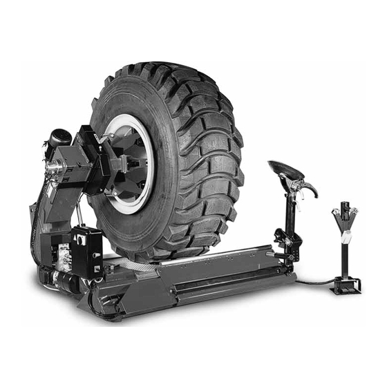
9500
Electro-Hydraulic Tire Changer
For Medium and Large Size Tires
IMPORCOM EQUIPOS AUTOMOTRICES
Blvd. Leyva Solano #830 A Pte.
Culiacan Sinaloa CP 80000
(667) 276 8141
(667) 716 0102
ID 92*1038450*4
1601 J. P . Hennessy Drive, LaVergne, TN USA 37086-3565 615/641-7533 800/688-6359
HENNESSY INDUSTRIES INC. Manufacturer of AMMCO
Installation Instructions
Operating Instructions
Safety Instructions
Maintenance Instructions
READ these instructions before placing unit in
service KEEP these and other materials delivered
with the unit in a binder near the machine for
ease of reference by supervisors and operators.
®
, COATS
®
and BADA
®
Automotive Service Equipment and Tools.
®
Manual Part No.: 8184344 02
Revision:
01/04
Advertisement
Table of Contents

Related Manuals for Coats 9500

Summary of Contents for Coats 9500
- Page 1 ® 9500 Electro-Hydraulic Tire Changer For Medium and Large Size Tires Installation Instructions Operating Instructions Safety Instructions Maintenance Instructions READ these instructions before placing unit in IMPORCOM EQUIPOS AUTOMOTRICES service KEEP these and other materials delivered Blvd. Leyva Solano #830 A Pte.
-
Page 2: Table Of Contents
8.0 Storing The Machine ....18 Your safety, or the safety of others, is involved! 10.0 Trouble Shooting ....19 ii • COATS 9500 Tire Changer... -
Page 3: Operator Protective Equipment
Only properly trained personnel should serv- ice tires on the 9500. Read all safety and M. Keep the work area well lighted. operating instructions thoroughly before N. Properly anchor the machine to the floor. -
Page 4: Bead Loosening Safety
Do not exceed the manufacturer’s recommended maximum inflation pressure. Failure to follow these instructions may cause the tire and rim to separate with tremendous force, resulting in serious per- sonal injury or death. iv • COATS 9500 Tire Changer... -
Page 5: Introduction
(fig.1). 1.1 Use limitations The COATS model 9500 tire changer is intended to be used as a device to demount and mount tubeless truck tires with the following specifications:... -
Page 6: Specifications
4 - 8 rpm Acoustic Pressure <70dBA 1.6 Dimensions Of The Machine Fig.3 #874009472 Mounting Clamp (fig.4). To hold the bead when mounting tires on steel rims. Instructions for use is in section 5.3. Fig.2 Fig.4 2 • COATS 9500 Tire Changer... -
Page 7: Optional Accessories
#874008257 Protectors for Alloy Rims (fig.7). #874019161 Extensions for 56” (fig.9/A). Suitable for rims with a center hole of 220 and 280 Necessary when clamping rims without flange and with a diameter exceeding 44” . Fig.7 Fig.9/A COATS 9500 Tire Changer • 3... -
Page 8: Carriage Instructions
Place the above-mentioned materials into a trash con- a service vehicle, the floor must have a capacity of at tainer and dispose per local regulations. least (330 lbs. x sq. ft.). Please contact COATS directly at 1-800-688-9240 to discuss options and other pre- cautions that may apply. -
Page 9: Installation Instructions
If not, reverse any two phase cables on the plug (i.e. Reverse the brown and the blue cable). CAUTION Any damage caused by the non-application of the above instructions shall not be cov- ered by the manufacturer and will void the warranty. COATS 9500 Tire Changer • 5... -
Page 10: Operating Instructions
Interrupt the con- trol engaged and operate only the desired movement in order to get normal operating speed. 7. To lift the tool holder arm, depress the pedal (#1 . Fig.15 6 • COATS 9500 Tire Changer... -
Page 11: Mounting And Demounting - General Precautions
(fig.16). Fig.17 Fig.16 CAUTION If the wheel is very heavy be sure to use a suitable external lifting device (i.e. fork lift, crane etc.). COATS 9500 Tire Changer • 7... -
Page 12: Demounting Tubeless Truck Tires (Up To 13" Wide)
5. Move the tool holder arm all the way in. Lower the arm and secure. Bring the tool in contact with the inner bead. 6. Loosen the inner bead as described in point #3 above. Fig.19 8 • COATS 9500 Tire Changer... - Page 13 8. Move to the front of the tire and hold it with both hands in the last part of demounting operation to pre- vent the tire from falling or rolling away out of control (fig.23). Fig.22 Fig.23 COATS 9500 Tire Changer • 9...
-
Page 14: Mounting Tubeless Truck Tires (Up To 13" Wide)
3. Lift the chuck arm and position the mounting hook or tubeless roller approximately 1.5 cm (1/2”) to the inside of the rim edge and approximately 1.5 cm (1/2”) away from the rim edge (fig.28). Fig.25 10 • COATS 9500 Tire Changer... - Page 15 WARNING Do not inflate the tire on the machine. This machine is not an inflation device. For inflation place the wheel in an approved inflation restraint device. Refer to OSHA standard number 1910.177. Fig.29 COATS 9500 Tire Changer • 11...
-
Page 16: Demounting Duplex And Supersingle Tubeless Truck Tires (Over 13" Wide)
4. Rotate the chuck counterclockwise until the outer bead is completely demounted (fig.31). Fig.33 2. Position the mounting hook about 3/4” (1.5 cm) to the inside of the rim edge and 1/2” (1 cm) away radi- cally. Fig.31 12 • COATS 9500 Tire Changer... - Page 17 WARNING Do not inflate the tire on the machine. This Fig.35 machine is not an inflation device. For inflation place the wheel in an approved inflation restraint device. Refer to OSHA standard number 1910.177. COATS 9500 Tire Changer • 13...
-
Page 18: Demounting Tires From Multi-Piece
6. When loosening the inner bead be sure not to damage the valve stem (fig.40). Fig.38 3. Turn the chuck counterclockwise and loosen the bead as described in #5.2.1.-5.2.3. Do not lubricate. Fig.40 14 • COATS 9500 Tire Changer... -
Page 19: Mounting Tires Onto Multi-Piece
For inflation place the wheel in an approved inflation restraint device. Refer to OSHA standard number 1910.177. Fig.43 4. Lubricate both beads and the rim surface (fig.44). Fig.44 COATS 9500 Tire Changer • 15... - Page 20 9. Lift the tool holder arm to the rest position. Shift the tire from the rim, moving the tool holder car- riage towards the outside: This will make it much eas- ier to remove the tube (fig.48). Tire Tool Fig.46 Fig.48 16 • COATS 9500 Tire Changer...
-
Page 21: Mounting Tractor And O.t.r. Wheels On One-Piece Rims
The edge of the hook should be about (1” or 2-3 cm) inflation restraint device. Refer to OSHA away radically from the rim edge and (1” or 2-3 cm) to standard number 1910.177. the outside. Fig.50 COATS 9500 Tire Changer • 17... -
Page 22: Maintenance
When putting the machine back in operation, first check the condition of all previously protected parts, and check for correct functioning of all devices before Fig.54 using the machine again. 18 • COATS 9500 Tire Changer... -
Page 23: Trouble Shooting
• The protectors for light-alloy • Replace the protectors for alloy wheels are damaged or worn out. wheels. • The check valve or manifold of • Call the authorized service center the chuck cylinder leak oil. for assistance. COATS 9500 Tire Changer • 19... - Page 24 The COATS ® Company warrants the 9500 Truck Tire Changer to be free of defects in workmanship and material for a period of twelve (12) months from the date of installation. Labor will be covered by the COATS ® Company for a period of 90 days from the date of installation.
Need help?
Do you have a question about the 9500 and is the answer not in the manual?
Questions and answers