
Related Manuals for Rosemount 396P

Summary of Contents for Rosemount 396P
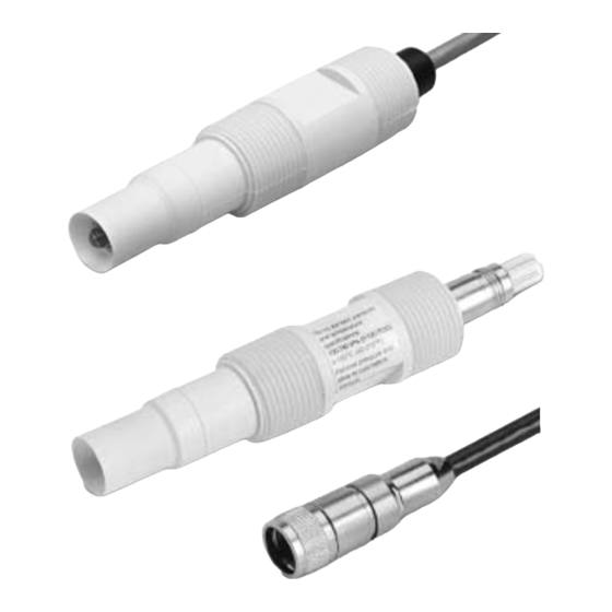
- Page 1 Instruction Manual PN 5100396P Models 396P and 396PVP February 2001 Combination pH/ORP Sensor MODEL 396P MODEL 396PVP with mating cable...
- Page 2 HAZARDOUS AREA INSTALLATION READ THIS PAGE BEFORE PROCEEDING! This sensor is not Intrinsically Safe. or Rosemount Analytical designs, manufactures, and tests Explosion Proof. Installations near flammable its products to meet many national and international stan- liquids or in hazardous area locations must dards.
-
Page 3: Table Of Contents
Number Title Page Recommended Accessories for First Time Installations .......... Wiring Matrix Guide - Model 396P ................Wiring Matrix Guide - Model 396PVP............... ORP of Saturated Quinhydrone Solution (In Millivolts) ..........Ro and R1 Values for Temperature Compensation Elements ........ -
Page 4: List Of Figures
Wire Functions for Model 396P with & without Preamplifier ....................Wiring Details Model 396P-01-50 for use with & without Junction Box (PN 22719-02) for Models 1181, 1050, & 1060 ..Wiring Details Model 396P-01-54 for use with & sithout Junction Box (PN 22719-02) for Models 1054/A/B, 2054, 2081 and Extension Cable (PN 9200254) ............................ -
Page 5: Features And Applications
100-790 kPa [abs] (0-100 psig) Minimum Conductivity 75 µS/cm, nominal; 100 µS/cm Integral Cable 396P: Code 01 - 25 ft; Code 02 - 15 ft coaxial 396PVP: none - must use mating VP cable Preamplifier Options 396P: Remote or Integral... -
Page 6: Ordering Information
Slotted Tip (not available on flat bulb sensors) 396P EXAMPLE NOTE: The Model 396P is also compatible with Models 1003 (option 02-50 only) and SCL-P/Q and (option 02-54 only). TABLE 1-1. RECOMMENDED ACCESSORIES FOR FIRST TIME INSTALLATIONS 1. Mounting Accessories (optional) Choose one: PN 915240-03, PVC flow through tee, 3/4 in. - Page 7 MODEL 396P and 396PVP SECTION 1.0 DESCRIPTIONS AND SPECIFICATIONS The Model 396PVP Sensor has similar features to the Model 396P. However, the Model 396PVP is offered with the new Variopol (VP) connector and uses a mating VP cable (purchased separately).
-
Page 8: Unpacking And Inspection
2.2.1 Flow Through and Insertion Mounting. Model 396P and 396PVP Sensors have a 1-inch MNPT CAUTION process connection at the front of the sensor for mounting into a 1-1/2 inch tee or the process pipes. -
Page 9: Dimensional Drawing
MODEL 396P and 396PVP SECTION 2.0 INSTALLATION SENSOR CABLE (OR VP CONNECTOR - NOT SHOWN) MILLIMETER INCH DWG. NO. REV. 40396P01 FIGURE 2-1. Dimensional Drawing SENSOR CABLE (OR VP CONNECTOR - NOT SHOWN) MILLIMETER INCH Process Connection Threads 3/4 inch... -
Page 10: Flow-Through And Insertion Installations
(INCLUDES: PEEK ADAPTER, 304 SST UNION FITTING) DWG. NO. REV. 40396P02 FIGURE 2-4. Model 396P with Insertion Mounting Adapter (PN 23242-02). Not for use with Model 396PVP. Mounting adapter allows for sensor removal without twisting or disconnecting interconnecting cable for ease of maintenance. -
Page 11: Submersion Installations
MODEL 396P and 396PVP SECTION 2.0 INSTALLATION WHEN INCH AND METRIC DIMS ARE GIVEN DWG. NO. REV. MILLIMETER 40396P03 INCH Handrail Mounting Assembly PN 11275-01 DWG. NO. REV. 40396P04 FIGURE 2-5. Submersion Installations... -
Page 12: Low Flow Cell Pn 23728-00
MODEL 396P and 396PVP SECTION 2.0 INSTALLATION MILLIMETER SENSOR CABLE INCH (OR VP CONNECTOR - NOT SHOWN) FIGURE 2-6. Low Flow Cell PN 23728-00 FIGURE 2-7. Jet Spray Cleaner PN 12707-00... -
Page 13: D D E E S S C C R R I I P P T T I I O O N N A A N N D D S S P P E E C C I I F F I I C C A A T T I I O O N N S
WIRING — MODEL 396P-01 Figures in this section provide the guidelines for wiring Signal cable should be run in a dedicated conduit the 396P-01 sensor to various Analyzer/Transmitter (preferably an earth grounded metallic conduit) instruments. and should be kept away from AC power lines. -
Page 14: Model 396P Ph
Please refer to Figures 3-1 through 3-6 for wiring Model 396P-01. Model 396P Option 01 (with preamplifier) cable Model 396P Option 02 (without preamplifier) cable FIGURE 3-1. Wire Functions for Model 396P with and without Preamplifier... - Page 15 SECTION 3.0 WIRING - MODEL 396P WHEN INCH AND METRIC DIMS ARE GIVEN MILLIMETER INCH DWG. NO. REV. 40396P15 FIGURE 3-2. Wiring Details Model 396P-01-50 for use with and without Junction Box (PN 22719-02) for Models 1181, 1050, and 1060.
- Page 16 WIRING - MODEL 396P WHEN INCH AND METRIC DIMS ARE GIVEN MILLIMETER INCH DWG. NO. REV. 40396P13 FIGURE 3-3. Wiring Details Model 396P-01-54 for use with and without Junction Box (PN 22719-02) for Models 1054, 1054A, 1054B, 2054, 2081, and Extension Cable (9200254).
-
Page 17: Wiring Details Model 396P-01-55 For Use With Junction Box (Pn 23550-00) For Models 54, 3081, 4081, And
MODEL 396P and 396PVP SECTION 3.0 WIRING - MODEL 396P WHEN INCH AND METRIC DIMS ARE GIVEN MILLIMETER INCH DWG. NO. REV. 40396P08 FIGURE 3-4. Wiring Details Model 396P-01-55 for use with Junction Box (PN 23550-00) for Models 54, 3081, 4081, and 81. -
Page 18: Wiring Details Model 396P-01-55 For Use With Models 54, 81, 3081, And 4081
MODEL 396P and 396PVP SECTION 3.0 WIRING - MODEL 396P FIGURE 3-5. Wiring Details Model 396P-01-55 for use with Models 54, 81, 3081, and 4081 FIGURE 3-6. Wiring Model 396P-01-( )--55 Sensor to Model 1055-10-22-32 Analyzer... - Page 19 MODEL 396P and 396PVP SECTION 4.0 WIRING - MODEL 396PVP SECTION 4.0 WIRING — MODELS 396P-02 AND 396PVP Figures 4-1 thru 4-22 provide the guidelines for wiring Signal cable should be run in a dedicated conduit the sensor to various Analyzer/Transmitter instruments.
-
Page 20: Wire Functions For Mating Variopol Cable Used With Model 396Pvp
Their Functions FIGURE 4-4. Wiring Details for Models 396PVP FIGURE 4-3. Wiring Details for Models 396PVP or 396P-02-50 with Mating Variopol Cable or 396P-02-55 with Mating Variopol Cable (PN 23645-07) for use with Model 1181 (PN 23645-07) for use with Model 81 FIGURE 4-5. -
Page 21: Junction Box (Pn 23555-00) To Model 54
(PN 23555-00) to Model 81 (PN 23309-03) to Model 1181 FIGURE 4-9. Wiring Details for FIGURE 4-10. Wiring Details for Models 396PVP or 396P-02-55 Models 396PVP or 396P-02-55 with with Mating Variopol Cable (PN 23645-07) for use with Remote Mating Variopol Cable (PN 23645-07) -
Page 22: Wiring Details For Models 396Pvp Or 396P-02-54 With Mating Variopol Cable (Pn 23645-07) For Use With Model 2700
MODEL 396P and 396PVP SECTION 4.0 WIRING - MODEL 396PVP FIGURE 4-11. Wiring Details for Models 396PVP or 396P- FIGURE 4-12. Wiring Details for Models 396PVP or 396P- 02-54 with Mating Variopol Cable (PN 23645-06) for use 02-55 with Mating Variopol Cable (PN 23645-07) for use with with Remote Junction Box (PN 23309-04) to Model 2081 Remote Junction Box (PN 23555-00) to Models 3081 &... -
Page 23: Wiring Details For Models 396Pvp Or 396P-02-55 With Mating Variopol Cable (Pn 23645-07) For Use With Remote
SECTION 4.0 WIRING - MODEL 396PVP FIGURE 4-15. Wiring Details for Models 396PVP or 396P-02-55 with Mating Variopol Cable (PN 23645-07) for use with Model 1055 FIGURE 4-16. Wiring Model 396P-(02)-( )--54/55-(61) Sensor to Model 1055-01-10-22-32 Analyzer FIGURE 4-17. Wiring Details for Models 396PVP or 396P-02-55 with Mating Variopol Cable (PN 23645-07) for use with Remote Junction Box (PN 23557-00) to Model 1055 NOTE: This wiring diagram can also be used for wiring a Model 396P-01. -
Page 24: Wiring Details For Models 396Pvp Or 396P-02-54 With Mating Variopol Cable (Pn 23645-07) For Use With Model 1054
(PN 23645-06) for use with Models 1054A/B & 2054 (PN 23645-07) for use with Model 1054 FIGURE 4-20. Wiring Details for Models 396PVP or 396P- FIGURE 4-21. Wiring Details for Models 396PVP or 02-54 with Mating Variopol Cable (PN 23645-06) for use... - Page 25 FIGURE 4-22. Wiring Details Model 396P-02-50 for use with Junction Box (PN 23309-03) and Remote Preamplifier, Extension Cable (PN 9200254). DWG. NO. REV. 40396P24 FIGURE 4-23. Wiring Details Model 396P-02-54 for use with Junction Box (PN 23309-04) and Remote Preamplifier (PN 22698-03), Extension Cable (9200254).
-
Page 26: Orp Of Saturated Quinhydrone Solution (In Millivolts)
SECTION 5.0 START UP AND CALIBRATION 1. While obtaining a process solution sample (it is recommended 5.1 MODELS 396P and 396PVP pH SENSORS that the sample is taken close to the sensor), record the pH value 5.1.1 SENSOR PREPARATION . Shake down the sensor that is shown on the analyzer/transmitter display. -
Page 27: Automatic Temperature Compensator
SECTION 6.0 MAINTENANCE SECTION 6.0 MAINTENANCE The Model 396P and 396PVP Sensors require mini- CAUTION mum maintenance. The sensor should be kept clean The solution used during the following and free of debris and sediment at all times. The fre-... - Page 28 MODEL 396P and 396PVP SECTION 6.0 MAINTENANCE 6.3 MODEL 396P and 396PVP ORP 6.3.2 Cleaning Platinum Electrode. The electrode can be restored to normal operation by simply cleaning 4.3.1 Platinum Electrode Check. The platinum elec- the platinum electrode with baking soda. Polish it by rub-...
-
Page 29: Troubleshooting With Advanced Diagnostics
MODEL 396P and 396PVP SECTION 7.0 DIAGNOSTICS AND TROUBLESHOOTING SECTION 7.0 DIAGNOSTICS AND TROUBLESHOOTING 7.1 MODEL 54/81/3081/4081 DIAGNOSTICS AND TROUBLESHOOTING The Model 54 Analyzer and Models 81 and 3081 Transmitters automatically search for fault conditions that would cause an error in the measured pH value, as does the Model 1054B pH/ORP Analyzer to a lesser degree. Refer to the applicable Instruction Manual for a complete description of the analyzer’s fault conditions. -
Page 30: Troubleshooting Without Advanced Diagnostics
MODEL 396P and 396PVP SECTION 7.0 TROUBLESHOOTING 7.2 TROUBLESHOOTING WITHOUT ADVANCED DIAGNOSTICS. Table 7-2, below, lists common problems, causes and remedies typically encountered in process measurement. TABLE 7-2. Troubleshooting without Advanced Diagnostics Problem Probable Cause Remedy Meter reads off scale. (Display... - Page 31 MODEL 396P and 396PVP SECTION 7.0 TROUBLESHOOTING TABLE 7-3. Model 396P and 396PVP pH/ORP Replacement Parts and Accessories DESCRIPTION QUANTITY 11275-01 Sensor Handrail Mounting Assembly 2002011 Flow Cell, CPVC, 1 inch FNPT 23242-02 Mounting Adapter, Insertion, 1¼-inch MNPT (304 S.S.) X 1” FNPT (PEEK)
-
Page 32: General
MODEL 396P and 396PVP SECTION 8.0 RETURN OF MATERIAL SECTION 8.0 RETURN OF MATERIAL 8.1 GENERAL. 8.3 NON-WARRANTY REPAIR. The following is the procedure for returning for To expedite the repair and return of instruments, proper communication between the customer and repair instruments that are no longer under warran- the factory is important. - Page 33 SAMPLE OR MATERIAL THAT HAVE BEEN EXPOSED TO OR USED IN AN ENVIRONMENT OR PROCESS THAT CONTAINS A HAZARDOUS MATERIAL ANY OF THE ABOVE THAT IS SUBMITTED TO ROSEMOUNT ANALYTICAL WITHOUT THE MSDS WILL BE RETURNED TO SENDER C.O.D. FOR THE SAFETY AND HEALTH OF OUR EMPLOYEES. WE THANK YOU IN ADVANCE FOR COMPLIANCE TO THIS SUBJECT.
-
Page 34: M M A A I I N N T T E E N N A A N N C C E
The Rosemount customer sales and service organization comprises a network of fully equipped support centers strategical- ly located throughout the world. From many of these locations, the Rosemount Group provides support, distribution of fin- ished products, repair facilities, and training for our customers. - Page 35 AND IMPLIED WARRANTIES OF MERCHANTABILITY AND FITNESS FOR A PARTICULAR PURPOSE. RETURN OF MATERIAL Material returned for repair, whether in or out of warranty, should be shipped prepaid to: Rosemount Analytical Inc. Uniloc Division 2400 Barranca Parkway Irvine, CA 92606...
- Page 36 CUSTOMER SUPPORT CENTER 1-800-854-8257 ON-LINE ORDERING NOW AVAILABLE ON OUR WEB SITE http://www.RAuniloc.com Credit Cards for U.S. Purchases Only. Rosemount Analytical Inc. Uniloc Division 2400 Barranca Parkway Irvine, CA 92606 USA Tel: (949) 863-1181 http://www.RAuniloc.com © Rosemount Analytical Inc. 2001...
Need help?
Do you have a question about the 396P and is the answer not in the manual?
Questions and answers