
Related Manuals for ENDEVCO IM136


Summary of Contents for ENDEVCO IM136
- Page 1 MODEL 136 DC AMPLIFIER INSTRUCTION MANUAL San Juan Capistrano, California, U.S.A. IM136 Revision D 30 September 1999...
-
Page 2: Table Of Contents
ENDEVCO MODEL 136 DC AMPLIFIER INSTRUCTION MANUAL TABLE OF CONTENTS SECTION 1: GENERAL DESCRIPTION PAGE INTRODUCTION......................2 DESCRIPTION ......................3 FUNCTIONAL CHARACTERISTICS ................3 KEY FEATURES ......................3 SECTION 2: INSTALLATION, FRONT AND REAR PANEL DESCRIPTION AND OPERATION INSTALLATION ......................4 FRONT PANEL DESCRIPTION.................. -
Page 3: Section 1: General Description Page
SIGNAL CONDITIONERS To support the use of its sensors in large scale testing, ENDEVCO has developed several generations of signal conditioner systems. Until recently, a state-of-the-art vibration laboratory set up consisted of a rack of manually controlled signal conditioners. -
Page 4: Description
300 Hz and 1,650 Hz. {See Section 2.4.15 Filter Options and Installation and Appendix 1, (Endevco Model 31875-XXXX-O)}. Up to three (3) Model 136 units can be installed in a 19” rack using ENDEVCO Model 31979 Rack Mounting Kit. -
Page 5: Section 2: Installation, Front And Rear Panel Description And Operation
INSTALLATION 2.1.1 UNPACKING The Endevco Model 136 DC Amplifier is shipped along with its instruction manual in one package. Carefully unpack and check all items for shipping damage. Report any obvious damage to the carrier immediately. If the shipping container or cushioning material is damaged, it should be kept until the contents of the shipment have been checked mechanically and electrically. -
Page 6: Front Panel Description
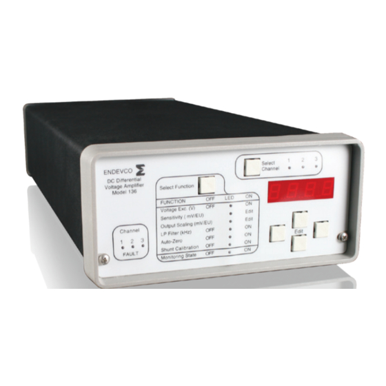
ENDEVCO MODEL 136 DC AMPLIFIER INSTRUCTION MANUAL FRONT PANEL DESCRIPTION Shown in Figure 1 is the Model 136 front panel. The front panel is a Mylar overlay, adhesively attached to the front panel aluminum plate. The Mylar overlay has cutouts for the six push buttons, and clear windows for 13 LED's and the 4-digit panel meter. -
Page 7: Rear Panel Description
Shown in Figure 2 is the rear view of the Model 136. Figure 2 Item 1, is the standard AC input power connector. The supplied Endevco power cable, PN EW599, is connected to this connector. (Note: The acceptable input power is 90 to 264 VAC, 50/60 Hz. -
Page 8: Rear Panel (Dc Input Power)
ENDEVCO MODEL 136 DC AMPLIFIER INSTRUCTION MANUAL Figure 3 is the optional Model 136-1 rear panel view. Item 1, is the DC input power connector. The input power requirements are: 9 to 18 volts DC and a maximum current of 1 amp. -
Page 9: Rs-232 Serial Communication Block Diagram
ENDEVCO MODEL 136 DC AMPLIFIER INSTRUCTION MANUAL RJ11 133 or 136 3 C hannel Amplifier EJ807 Adapter DB9F RJ11 RJ11 133 or 136 3 Channel Amplifier To PC Controller Figure 5 Figure 5 is the block diagram for the RJ-11 RS-232 computer control connector. -
Page 10: Mod Jack, Front View
ENDEVCO MODEL 136 DC AMPLIFIER INSTRUCTION MANUAL Not Used Digital Ground Analog Ground Digital Ground 1 2 3 4 5 6 Figure 6 Figure 6 is the RJ-11, Modular Jack, Front View RS-232 RJ11 Pin Assignment: Pin 1: Analog Ground... - Page 11 ENDEVCO MODEL 136 DC AMPLIFIER INSTRUCTION MANUAL WARNING OF POSSIBLE CATASTROPHIC DAMAGE TO SENSORS Up to 24 VDC may be temporarily present on the excitation lines (P+: pin 7, and P-: pin 8) during the first 12 seconds after applying power to the unit. To avoid this, the excitation sense lines (PSEN+: pin 1, PSEN-: pin 6) must be connected as shown in figure 5 or figure 6.
-
Page 12: Typical Bridge Connection
ENDEVCO MODEL 136 DC AMPLIFIER INSTRUCTION MANUAL Model 136 9 Pin "D" Connector PSEN+ PSEN - Figure 8 Typical Bridge Connection PSEN + PSEN- Figure 9 Typical Bridge Connection With Remote Excitation Sensing IM136 Page 11... -
Page 13: Operation
INSTRUCTION MANUAL OPERATION The Endevco Model 136 can be manually programmed from the front panel (See Figure 1) by means of a “Select Channel” push-button, three (3) “Channel LEDs”, a “Select Function” push-button, seven (7) “Function LEDs” indicating which function has been selected by the “Select Function”... -
Page 14: Query/Programming Mode
ENDEVCO MODEL 136 DC AMPLIFIER INSTRUCTION MANUAL 2.4.3 Query/Programming Mode The Query/Programming Mode allows for manual programmability and querying of the programmable functions. This Mode is activated by pressing the “Select Function” push- button. A function is queried by selecting it using the “Select Function” push-button. The current setting for the selected function will be displayed on the LED display. -
Page 15: Excitation Voltage
This function selection provides for programming the sensitivity of the transducer (in mV/EU). The Endevco Model 136 uses this information to determine the gain needed to achieve the required output scaling. The left-right EDIT keys select the number position in the LED display, and the up-down EDIT keys increment or decrement the selected number. -
Page 16: Low Pass Filter
ENDEVCO MODEL 136 DC AMPLIFIER INSTRUCTION MANUAL 2.4.8 Low Pass Filter This function selection provides for enabling or disabling the built-in 4-pole Butterworth Low Pass filter (set by header module 31875). The following messages will be shown sequentially on the LED display each time the up-down EDIT keys are pressed: (1) “OFF”, and (2) “XX.XX”. -
Page 17: Monitoring State
ENDEVCO MODEL 136 DC AMPLIFIER INSTRUCTION MANUAL 2.4.11 Monitoring State This function selection provides for programming the desired state of the amplifier while in the normal mode of operation (described in 2.2 and 2.3 above). The following messages will be shown sequentially on the LED display each time the up-down EDIT keys are pressed: (1) “EU”, (2) “Vout”... -
Page 18: Special Modes
ENDEVCO MODEL 136 DC AMPLIFIER INSTRUCTION MANUAL 2.4.12 Special Modes The special modes are not frequently used and they may be selected by pressing the “Select Function” key while simultaneously pressing a combination of multiple EDIT keys. The unit must be in the normal mode of operation to enter any of the special modes of operation. The table below shows the combination of the EDIT keys that need to be pressed to obtain the desired special mode. - Page 19 ENDEVCO MODEL 136 DC AMPLIFIER INSTRUCTION MANUAL After the mode is selected, all of the “Function LEDs” will be OFF and the first error code will be shown on the LED display. The user may scroll through the list by using the UP and DOWN EDIT keys.
- Page 20 ENDEVCO MODEL 136 DC AMPLIFIER INSTRUCTION MANUAL The user selects which calibration constant is being set by subsequently pressing the “Select Function” key. Each press of the “Select Function” key will sequentially make one of the “Function LEDs” blink indicating that the calibration constant is selected for programming and the corresponding calibration constant will be shown on the LED display.
-
Page 21: Fault Indication
Filter Options and Installation 1. Introduction The ENDEVCO Model 31875 plug in, Low Pass Filter Modules are optional Butterworth filters designed for use with the Endevco Model 133, PE and ISOTRON Signal Conditioner and Model 136, DC Amplifier. The filters are low-cost designs with sufficient corner frequencies to accommodate most test requirements. -
Page 22: 2.4.16 Sample Set Up
ENDEVCO MODEL 136 DC AMPLIFIER INSTRUCTION MANUAL 2. Filter Change/Replacement Place the model 136 on a level, firmly supported surface. Remove the two front panel screws. Leave the front panel connector connected to the main board. Carefully slide the black cover from the unit. - Page 23 ENDEVCO MODEL 136 DC AMPLIFIER INSTRUCTION MANUAL accomplished with the top and bottom "Edit" buttons to increase or decrease the value. The left and right "Edit" buttons move the significant digit on the DPM to be changed. The actual value must be within the range of 0.001 to 9999.) 4.
-
Page 24: Rack Mounting Kit
Model 136. Gently remove the plastic frame from the Model 136 front panel (store the panel for future use and for return of the unit to Endevco when required). Hold the Model 136 behind the front panel mount, (the part with three cut-out rectangular holes), gently insert the Model 136's front panel through the correct position to be mounted. -
Page 25: Section 3: Routine Maintenance And Handling
Endevco for repair/replacement. Should a faulty unit be returned to Endevco, it is suggested that the original or equivalent packaging be used. This will reduce damage to the equipment during shipment. -
Page 26: Ordering Information And Accessories
INSTRUCTION MANUAL Ordering Information and Accessories ENDEVCO ® Model 136 must be specified in the following manner: 136-X If no filter is specified at time of order entry, the standard default filter installed is a 10 kHz low pass Butterworth. - Page 27 ENDEVCO MODEL 136 DC AMPLIFIER INSTRUCTION MANUAL SECTION 4: APPENDIX 1 FILTER MODULE MODEL 31875 DATA SHEET SECTION 4: APPENDIX 1 FILTER MODULE MODEL 31875 DATA SHEET The choices of Butterworth filter corner frequencies are as follows: (Hz) Part number to...
-
Page 28: Model 31875-Xxxx-O Filter Data Sheet 26 2. Serial Communication
ENDEVCO MODEL 136 DC AMPLIFIER INSTRUCTION MANUAL APPENDIX 2 SERIAL COMMUNICATION Communication Protocol - Each transmission is of the form: [Header] [;] [Body] The Header and Body are separated by a semi-colon and are each made up of several components separated by one space. - Page 29 ENDEVCO MODEL 136 DC AMPLIFIER INSTRUCTION MANUAL 1) The order of these items is fixed. For Model 133 the order is Input Select to Monitoring, for Model 136 the order is Voltage Excitation to Monitoring. For the range of possible settings for each item see the sections below on model specific hardware control.
- Page 30 ENDEVCO MODEL 136 DC AMPLIFIER INSTRUCTION MANUAL Response Data (conditional): The following sections describe the response of the 13x to commands that require it to send data (all data described below follows a transmission Header identical to that described above).
- Page 31 ENDEVCO MODEL 136 DC AMPLIFIER INSTRUCTION MANUAL NAK (0x0C) - This response indicates either a bad checksum was calculated or there was not enough data transfered to satisify the command requirements (i.e. a setup command with less that 7 items).
- Page 32 ENDEVCO MODEL 136 DC AMPLIFIER INSTRUCTION MANUAL ASCII Representation of string; 257\s0\s0;3000\s2123\s3456\s1000\s2000\s1000\s1000\s187 Binary Representation of ASCII string (these are the bytes actually transmitted via rs-232 in decimal); 50,53,55, 32,48,32,48,59,51,48,48,48,32,50,49,50,51,32,51,52,53,54,32,49,48,48,48,32, 50,48,48,48,32,49,48,48,48,32,49,48,48,48,32,49,53,56,55 Where; 1. ASCII ‘257’ (50,53,55) is the result of the binary operation ((1 << 8) | 1). Where 0=Model 136 and 1 is the unit number (this binary number is then converted to an ASCII string).
Need help?
Do you have a question about the IM136 and is the answer not in the manual?
Questions and answers